國 立 交 通 大 學
網 路 工 程 研 究 所
碩 士 論 文
ARM指令集架構應用程式之靜態二進位轉譯及最佳
化
On Static Binary Translation and Optimization for
ARM-based Applications
研 究 生:陳俊宇
指導教授:楊 武 博士
ARM指令集架構應用程式之靜態二進位轉譯及最佳
化
On Static Binary Translation and Optimization for ARM-based
Applications
研 究 生:陳俊宇 Student:Jiunn-Yeu Chen
指導教授:楊 武 博士 Advisor:Dr. Wuu Yang
國 立 交 通 大 學
網 路 工 程 研 究 所
碩 士 論 文
A Thesis
Submitted to Institute of Networking Engineering College of Computer Science and Information Engineering
National Chiao Tung University in partial Fulfillment of the Requirements
for the Degree of Master
in
Institution of Network Engineering June. 2008
Hsinchu, Taiwan, Republic of China
ARM指令集架構應用程式之靜態二進位轉譯及最佳
化
學生:陳俊宇 指導教授:楊 武 博士
國立交通大學網路工程所碩士班
摘 要
二進位碼的轉譯經常被用於將現有的程式移轉到新開發的指令集平台上。這篇 論文裡將探討一個靜態二進位碼轉譯器,此轉譯器能將ARM指令集架構的二進位碼轉 譯成類MIPS指令集架構的二進位碼,這個類MIPS指令集架構是專為嵌入式系統設計 的新架構。此靜態轉譯器的功能包含基礎指令集架構轉換,以及以減少執行指令數 為目標的最佳化。由於ARM指令集架構是一個條件式執行的指令集架構,在轉譯的過 程中需要特別處理條件式執行的指令,也因此轉譯器對於條件式執行亦頇提供最佳 化。在經過各種對條件式執行的最佳化後,在我們用來評估效能的EEMBC程式集中, 相對於被轉譯的ARM二進位碼,經由轉譯得到的二進位碼只需要額外執行35%的指令On Static Binary Translation and
Optimization for ARM-based Applications
Student: Jiunn-Yeu Chen Advisor: Dr. Wuu Yang
Institute of Network Engineering
National Chiao Tung University
Abstract
Binary translation is often used in migrating legacy binaries to new architecture-based platforms. This thesis describes a static binary translator which translates ARM binaries to a MIPS-like architecture designed for embedded systems. The static translator handles basic architecture translations and performs optimizations to minimize instruction overhead. The conditional execution feature in the ARM architecture requires special attention on binary translation and optimization. With several optimizations to minimize condition updates and checks, the translated code from ARM to our target architecture increases the instruction path length by only 35% on the EEMBC benchmark.
誌 謝
關於這篇論文的完成,首先我要感謝論文指導老師楊武教授,以及主持這 項計畫的徐慰中教授。兩位老師在研究上的指導以及提點,讓我能夠一步步完 成研究,也感謝兩位老師總是很有耐心的與我討論並給予我建議,讓我得以不 斷的修正及嘗試,練習研究的方法及培養研究的態度。感謝晶心科技的技術長 蘇泓萌博士在硬體方面給予的建議,並對研究方向給予不少實用的提問。感謝 一起合作這項計畫,現於美國普林斯頓大學攻讀博士學位的的洪資涵,在合作 過程中給予我相當大的啟發。 感謝給予指導的博士班學長及程式語言與系統實驗室的所有夥伴們,很榮 幸能與你們一起度過研究生活。感謝柏瞱學長不吝分享研究的知識,讓我在專 注此研究之餘也對資訊領域的其他技術有更多的認識;感謝禮君,帥維,奕圻, 你們是互相打氣的好夥伴;感謝德發,耀崙,有倫,冠旭,培翔幾位學弟,祝 你們研究順利。 感謝這兩年陪伴我的朋友們,讓我研究,生活得以平衡的朋友們。同校多 年的死黨彭彭,大學的室友沈老二,牛,阿婆,生活上給予我很多幫助的阿吉, 予中,廷潮,喻暄,以及交大資科的同學們,感謝你們提供的支援,並且使我 研究生活不致單調。 最後感謝我的家人,我的父母及兄長,感謝你們包容一個彆扭的小孩,如 果不是你們悉心的教導,我不會有機會從事並完成這項研究,由衷的感謝。 僅將這篇論文獻給你們。Table of Contents
摘 要………...…ii Abstract……….…iii 誌 謝………...iv Table of Contents………...v List of Tables………vii List of Figures……….viii Chapter 1 Introduction……….1Chapter 2 Code Generation Overview……….4
2.1 PC-relative Data Access...4
2.2 Shifter Operand and Shifter Carry Out………5
2.3 Conditional Execution……….…6
2.4 Condition Flag Handling……….9
2.5 Processor Mode and Thumb Instruction Set………..10
2.6 Register Mapping………...11
2.7 Executable Layout……….12
2.8 Control Flow Graph………..15
2.9 Control Flow Management………...15
2.9.1 Lazily Update to ARM PC……….16
2.9.2 Indirect Branch Handling………..16
2.9.3 Address Mapping Table……….17
2.9.4 Return Address Stack……….19
2.9.5 Switch Table Lookup………..20
Chapter 3 Code Optimization Overview………...21
3.1 PC-relative Data Access Optimization……….21
3.2 Check Condition Code Selectively………22
3.3 Update Condition Flags Selectively………..23
3.4 Special Condition Flags……….24
3.5 Combined Conditional Branch……….25
3.6 Other Optimizations………..26
Chapter 4 Results and Analyses……….28
4.1 Simulators………...28
4.2 Benchmarks………28
Chapter 5 Experimental Results……….30
5.1 Baseline Code Generation……….30
5.2 Selectively Check Condition Code………31
5.3 Selectively Update Condition Flags………..32
5.4 Combined Conditional Branch……….33
5.5 Special Condition Flag………...33
5.6 Check Inverse Condition Code Selectively………..33
5.7 Register Remapping………...34
5.8 Local Optimization Estimation……….36
5.11 Switch Table Lookup………...40
5.12 Comparison of Code Size………41
Chapter 6 Conclusions……….44
List of Tables
Table 1. Frequency of PC-relative data accesses in the EEMBC benchmark………...P.5 Table 2.Frequency of the shifter operands in the EEMBC benchmark, including logical shift left (LSL), logical shift right (LSR), and arithmetic shift right (ASR)…………....P.6 Table 3. Frequency of the condition code check in the EEMBC benchmark…………...P.7 Table 4. Frequency of instructions that update condition flags in the EEMBC benchmark……….P.9 Table 5. New register allocation for the target architecture. The ones mapped to the 16 ARM registers (i.e. r0-r11 and r28-r31) are excluded………P.12 Table 6: Code template of the conditional moves of differ ent condition code checks………...P.18 Table 7: Percentage of conditional branches in ARM binary and the MIPS’ binary…..P.39 Table 8: A comparison of the executable’s size of the source program and the target program………...P.40 Tablee 9: A comparison of the .text section sizes of the source program and the target program………...…P.41 Table 10: A comparison of the total sizes of the source program and the target program………...…P.41 Table 11: A comparison of the total sizes of the source program and the target program………..……….P.42 Table 12: A comparison of the non-text section sizes of the source program and the target program………...P.42 Table 13: The percentage of non-text section sizes in total sizes in the ARM executable………...…P.43 Table 14: A comparison of the non-text section sizes of the source program and the target program...P.43
List of Figures
Figure 1. All 16 condition codes in the ARM architecture. N, Z, C, and V mean the respective condition bits are set………....P.8 Figure 2. Memory layout of the original ARM executable and the translated executable. In 2.b, MIPS’ is the target architecture, and RAS is the return address stack………….P.13 Figure 3. New layout of the translated executable is showed in 3.b. Compared with 2.b, the new sections are moved between the ARM.Bss section and the ARM.Heap section……….P.14 Figure 4. Example of translating two conditional instructions with the same condition. The condition-code check of the second ARM instruction is eliminated………...P.23 Figure 5. Example of two conditional instructions with a reverse condition. The branch offset of the first instruction is modified as shown in bold face………...P.23 Figure 6. An example of replacing ordinary condition flags with special conditions flag………..P.25 Figure 7. Performance improvement from various optimizations. (Y-axis shows the executed instruction count ratio.)………...P.35 Figure 8: Estimation of the potential of local optimization (Blue bars: before local optimization; Red bars: after local optimization)………...P.36 Figure 9: comparison of the instruction count ratio and the cycle count ratio between the two architectures……….P.38
Chapter 1 Introduction
Binary translation, the process of translating one binary executable into a different binary executable, has been commonly used in various applications, such as ISA (Instruction Set Architecture) migration [1][2][3][4], static binary instrumentation [5][6], fast architecture simulation [7], dynamic binary instrumentation [8][9], and runtime optimization [10][11][12].
In general-purpose ISA migration, using dynamic binary translation has almost become a standard procedure. For example, Aries [2] migrates HP-PA binaries to the IA-64 architecture, Rosetta [4] migrates Power PC code to IA-32, IA-32EL [3] migrates IA-32 executables to IA-64. The primary purpose of using process virtual machines [14] to migrate existing application executables is to support compatibility. However, some dynamic binary translation systems are used to increase the applications available on a new platform. For instance, DEC FX!32 [1] was developed to make numerous IA-32 applications available to the DEC Alpha platform. A successful binary translation system could certainly reduce the time-to-market requirement for having a large number of applications available for a newly defined ISA. The number of ISAs in general-purpose computing has been declining in the past several years. Few companies can afford to support and maintain their proprietary ISA. However, in the embedded system area, new architectures have often been introduced. Using binary translation to migrate embedded applications may become commonplace in the future.
In general-purpose computing, dynamic binary translation has been used more often. A dynamic binary translation system normally will incur significant overhead on program
start-up where the legacy binary must be translated on the first invocation. However, since the most important factor of binary translation in this area is to make legacy applications available to users, the performance of a migrated application is of secondary importance. For embedded systems, the consideration may be different due to some additional important requirements. For example, a migrated application should have reasonably fast start-up since embedded system users may have less patience for a slow start-up. The requirement of high energy efficiency also plays an important role that limits the use of dynamic binary translation. This implies both the execution time and the space overhead of the translated binary should be acceptable. With such requirements in mind, a mix of static and dynamic translation approach to migrate embedded applications becomes more attractive.
Static translation has the advantage of avoiding the translation overhead at runtime. With that advantage, a static translation system can perform more time-consuming, but performance-critical optimizations to improve the code quality and to reduce the space required for the generated code. As a matter of fact, more and more embedded binaries are generated by compilers rather than hand coded. Compiler generated code is much more friendly to static binary translators. Therefore, a mixed approach would let the static translator handle most of the code in an application, and let the dynamic translator handle the cases left by static translation.
In this report, we present a static binary translator which is part of our mixed static/dynamic binary translation system. This static binary translator converts ARM-based binary code to the MIPS’ architecture. We show that the EEMBC [17] benchmark suite can be translated correctly with minimal loss of execution efficiency (with optimization, the translated instruction path length is increased by less than 35%).
In Chapter 2, we describe the high-level view of the static translator and how it handles typical binary translation issues like (a) code discovery problems and (b) code location problems for indirect branches [14]. We also discuss how unique architecture features in ARM, such as conditional execution, are translated to MIPS’. Chapter 3 provides details on the optimizations implemented in our translator to minimize the overhead of flag emulation. Chapter 4 gives our experiment setup, including the simulators and the benchmark used in the study. Chapter 5 discusses the performance of our static binary translation on the benchmark suite. Chapter 6 summaries and concludes this report.
Chapter 2 Code Generation Overview
For our static binary translator, the source architecture is ARM. Just like IA-32 executables dominate general-purpose computing applications, ARM executables dominate embedded applications. Our target architecture is the MIPS’ architecture, which is similar to MIPS with some additional features, such as 16-bit instructions and load/store multiple words instructions. Here we highlight the translation issues for the major differences between the source and the target architectures.
2.1 PC-relative data access
There are data embedded in the text section of the ARM binary. For example, a load instruction can access such data using PC-relative addressing as follows:
ldr r1, [pc + 0xoffset]
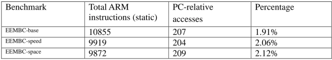
The data embedded in the text section are mainly large immediate that cannot fit in the immediate field and the jump table for switch statements. From the perspective of code generation, the generated target machine code will reference the location in the text section. In Chapter 3, we will discuss how tooptimize the PC-relative data accesses. Since we need to keep the text section around for the dynamic translator to handle exceptions and corner cases at runtime, PC-relative data accesses can get the needed data from the preserved text section. Although PC-relative data accesses are not frequent, they do exist. Table 1 shows the relative frequency of such instructions in the ARM binary for the EEMBC benchmark, compiled by the GCC compiler. EEMBC-base is
compiled with no optimization (i.e. –O0), EEMBC-speed is compiled with optimization for speed (i.e. –O2), and EEMBC-space is compiled with optimization for space (i.e. –Os).
Benchmark Total ARM
instructions (static) PC-relative accesses Percentage EEMBC-base 10855 207 1.91% EEMBC-speed 9919 204 2.06% EEMBC-space 9872 209 2.12%
Table 1. Frequency of PC-relative data accesses in the EEMBC benchmark.
2.2 Shifter Operand and shifter carry out
The general ARM instructions support a shifter operand. For example, in the following add instruction:
add r0, r 1, r2, lsl #2
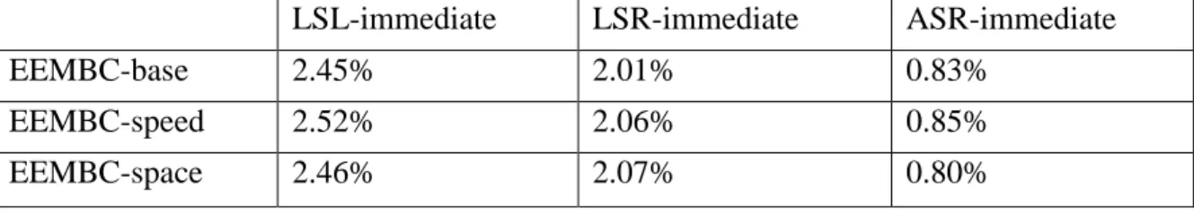
The third operand, register r2, shall be shifted left by 2 before it is used by the add instruction. Our target architecture does not support such shifter operands, so additional instructions are needed to implement the shift operation. Fortunately, shifter operands are not that frequent in ARM binaries. Table 2 shows the frequency of some commonly used shifter operands.
As the shifter operand is generated, shifter carry out [18] is also generated at the same time. Though the shifter carry out is not directly used by the operations, such as the
add in the example, it is used to update the condition flag Carry. Thus, additional
LSL-immediate LSR-immediate ASR-immediate EEMBC-base 2.45% 2.01% 0.83%
EEMBC-speed 2.52% 2.06% 0.85% EEMBC-space 2.46% 2.07% 0.80%
Table 2. Frequency of the shifter operands in the EEMBC benchmark, including logical shift left (LSL), logical shift right (LSR), and arithmetic shift right (ASR).
2.3 Conditional execution
Conditional execution is a mechanism to perform predicated execution. In the ARM ISA, almost all instructions are predicated instructions (with the exception of certain v5T instructions). Four flag bits stored in the CPSR (Current Program Status Register) register are used to decide if the instruction should be executed. The four flag bits are named as Negative (N), Zero (Z), Carry (C) and Overflow (V) and these four condition bits are illustrated in Figure 1.
There are sixteen different conditions as shown in Figure 1. Some of the condition checks only need to examine one specific bit, and some need to check multiple bits. The code generated for each check will be different. For example, the following addeq instruction checks if one condition bit is set. On the other hand, the addge instruction shown on the right side of the addeq instruction checks if the N flag is equal to the V flag. In the following code example, r15 is allocated to hold condition flags (CPSR), and r21, r22, r23 are temporary registers.
ARM :
addeq r0, r1, r2 addge r0, r1, r2
MIPS’:
beqz r21, 8 btst r22, r15, 3 add r0, r1, r2 sub r23, r21, r22
beqz r23, 8 add r0, r1, r2
Instructions with condition code AL do not need to check any condition bits, and the instructions with NV are never executed (like a NOP) except for some extensions in v5T [18]. Our translator generates one or multiple branches to handle condition checks. If the specified condition is not met, the attempted operation is skipped. In the EEMBC benchmark, conditionally executed instructions are used rather frequently. Table 3 shows the percentage of all executed ARM instructions that specify conditions other than AL and NV.
Check condition code EEMBC-base 10.27%
EEMBC-speed 19.57% EEMBC-space 19.84%
Opcode Mnemonic Meaning Condition flag state
0000 EQ Equal Z
0001 NE Not equal !Z
0010 CS/HS Carry set/unsigned high or same C 0011 CC/LO Carry clear/unsigned lower !C 0100 MI Minus/negative N 0101 PL Plus/positive or zero !N
0110 VS Overflow V
0111 VC No overflow !V
1000 HI Unsigned higher C && !Z 1001 LS Unsigned lower or same !C || Z 1010 GE Signed greater than or equal N == V 1011 LT Signed less than N != V
1100 GT Signed greater than Z == 0 && N == V
1101 LE Signed less than or equal Z == 1 || N != V
1110 AL Always Any
1111 NV Special use None
Figure 1. All 16 condition codes in the ARM architecture. N, Z, C, and V mean the respective condition bits are set.[18]
2.4 Condition flags handling
The four condition flags in the ARM ISA are N, Z, C, and V. They are located at bits [31:28] of the CPSR register. Two types of ARM instructions modify these four flags: the comparison instructions, and the ALU instructions or the move instructions with the s-bit set.
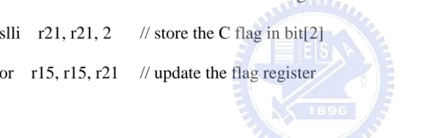
One target register can be preserved to store the four condition flags. However, to access such bits is rather expensive since it requires at least two instructions (i.e. a shift and a logical OR) to update one condition flag.
/* Instructions that calculate the new C flag */ slli r21, r21, 2 // store the C flag in bit[2] or r15, r15, r21 // update the flag register
The overhead for updating condition flags increases for instructions that set more condition bits. Table 4 shows the frequency of all executed ARM instructions in EEMBC that need to update the condition flags.
Percentage
EEMBC-base 9.49%
EEMBC-speed 14.99% EEMBC-space 15.18%
Table 4. Frequency of instructions that update condition flags in the EEMBC benchmark.
In order to minimize instruction overhead for condition flag updates, we allocate each of the four flags in separate target registers. This would avoid the shift operations for each flag update. However, the downside is the use of three more registers which might be better used for some optimizations which require additional temporary registers. Since our target architecture has 16 more general-purpose registers than the ARM architecture, we can afford reserving four registers for the condition flags, given that the frequency of flag update is fairly high in the ARM application binaries.
2.5 Processor mode and Thumb instruction set
ARM supports regular execution mode and the Thumb execution mode. The Thumb execution mode allows 16-bit ARM instructions to be used. Using Thumb execution code can effectively reduce the code size, and is considered important for many embedded applications. A special instruction, bx, must be used to switch between the Thumb execution mode and the regular ARM mode. The bx instruction format is as follows:
Bx r1
The execution will bring the processor to the Thumb mode if the least significant bit of register r1 is 1. Otherwise, the processor stays in the ARM mode. Since the prefix of a Thumb instruction is similar to that of an ARM instruction, the translator must know the execution mode to correctly parse the instructions. Therefore, this feature makes static translation difficult because the value of register r1 may not be known at translation time. Our static translator does not handle Thumb instructions. Thumb mode execution will be handled by the dynamic translator.
2.6 Register mapping
There are 31 general-purpose registers in the ARM architecture, but only 16 of them are visible to programmers and compilers. The rest are used to speed up exception handling. Furthermore, registers r8-r14 are banked, which means there are multiple physical copies of each register. Which physic registers are actually referenced depends on the current execution mode. Our static binary translator supports only user mode, so we do not need to take care of which physical registers are used. The number of ARM registers needs to be maintained as part of the architecture state is 16. The MIPS’ architecture has 32 32-bit general-purpose registers, so the 16 ARM registers can be mapped directly as a subset of the target architecture registers. It is worth noting that the register r0 in MIPS’ is not a constant zero as is in the MIPS architecture.
Register mapping is conducted in two steps: (a) ARM registers r0 to r11 are mapped to MIPS’ architecture registers r0 to r11, and (b) ARM registers r12 to r15 are mapped to target registers r28 to r31. ARM registers r12 to r15 are special registers such as PC, LR, SP, and so on. Mapping them to consecutive target registers is preferred so that we may translate the load/store multi-word instructions in ARM directly into similar load/store multiple word instructions in the target ISA which requires the registers to be contiguous.
Other than the 16 registers reserved for mapping to ARM registers, the remaining registers in the MIPS’ architecture are used for temporary registers and for special usages such as the shifter operand. In our current translator, five of them are used as temporary registers, two of them are reserved for handling privileged mode, and four of them are saved for future usage.
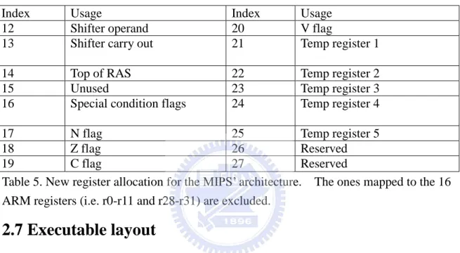
In section 2.4.1 we discussed the need to allocate registers to hold each condition flag so that the cost of flag update and check can be significantly reduced. Initially, we allocated the four condition flags in one register (r15, a mapped register for CPSR). Now we separated them out and assigned one register for each. The allocation of the target registers not mapped to the 16 ARM registers is listed in Table 5.
Index Usage Index Usage 12 Shifter operand 20 V flag
13 Shifter carry out 21 Temp register 1 14 Top of RAS 22 Temp register 2 15 Unused 23 Temp register 3 16 Special condition flags 24 Temp register 4 17 N flag 25 Temp register 5 18 Z flag 26 Reserved 19 C flag 27 Reserved
Table 5. New register allocation for the MIPS’ architecture. The ones mapped to the 16 ARM registers (i.e. r0-r11 and r28-r31) are excluded.
2.7 Executable layout
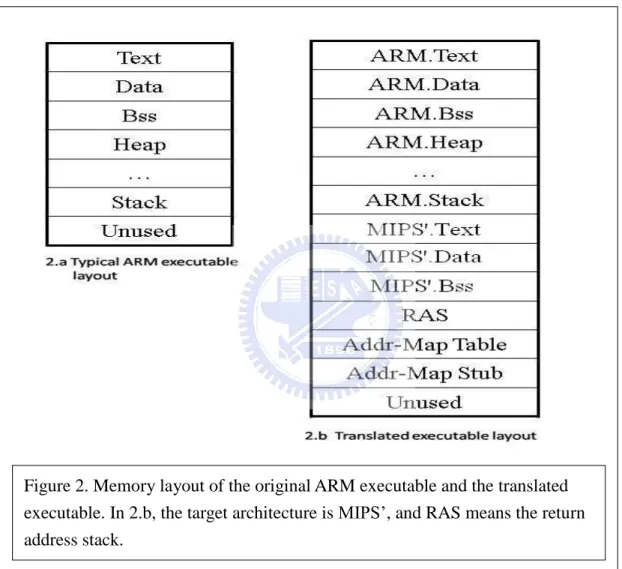
Layouts of ARM and MIPS’ executables are contrasted in Figure 2. The binary layout of the target executable can be divided into three parts: the ARM program sections, the MIPS’ program sections, and the control management sections. The original ARM program sections are stored as part of the MIPS’ executable. Keeping the ARM program sections is needed for future dynamic translation, and it also allows the target program to access the data in the ARM program sections. All the ARM sections are allocated in the same address as in the original ARM executable. This decision makes the memory accesses much easier to handle, since no additional computation is needed to calculate the memory address of the operands.
allocated in higher memory address since the lower addresses are used for the ARM sections. The control management part has return address stack (RAS), address mapping table, and address stub sections. The purpose of these three sections will be discussed in section 2.9.
This initial binary layout allocated the ARM binary in the same address space as an original binary. This approach has the advantage that all address computation in the ARM binary can remain the same (such as relocation). The newly generated MIPS’ code and the supporting data structure, such as the address mapping table, were allocated to the address space not used by the ARM binary. However, we later encountered some
Figure 2. Memory layout of the original ARM executable and the translated executable. In 2.b, the target architecture is MIPS’, and RAS means the return address stack.
applications that used such memory space for I/O buffers. This would cause instructions or the address mapping table to be modified at runtime.
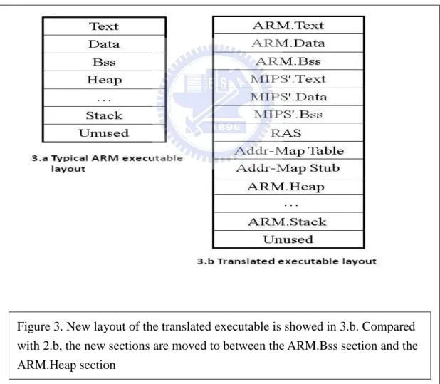
To avoid this type of memory address overlap, we propose a new binary layout. In the new binary layout, we allocate the translated MIPS’ code and the control management code and data before the ARM.heap section. Allocating the new code in the heap is safer because heap is for dynamic memory allocation, and programmers should never presume how heap space is allocated. One possible downside of this new approach is that the heap space is reduced by a small amount.
Figure 3. New layout of the translated executable is showed in 3.b. Compared with 2.b, the new sections are moved to between the ARM.Bss section and the ARM.Heap section
2.8 Control flow graph
Like other static binary translation tools [5][6], we also build the control flow graph of each translation unit. The control flow graph serves the purpose of control management and code optimization.
Our translator constructs the control flow graph by recognizing potential basic blocks and establishing the relation between different blocks. The usual way to recognize basic blocks in binary code is to identify the leader of each basic block. Typical leaders are instructions following direct or indirect branches, instructions targeted by direct branches, and the program entry point. Here we must handle one additional case: the addresses for PC-relative data. The basic blocks contain PC-relative data are identified to prevent treating PC-relative data as instructions, so they are excluded from the control flow graph.
The control flow graph we built is not precise because the targets of indirect branches may not be known at translation time. In Chapter 3, we will discuss code optimizations implemented in our translator. Since some optimizations are based on the control flow graph, and if there is an indirect branch to the middle of a basic block, our code optimization may become invalid. Therefore, when the address mapping routine discovers at runtime that the target of an indirect branch is not a recognized basic block, it will throw an exception and transfer control to our runtime translation system to handle such cases.
2.9 Program control management
and indirect branches. The following subsections describe mechanisms used in the translator to manage control transfers.
2.9.1 Lazy update to PC
In the generated code, updating the ARM-PC is required since other instructions may reference the PC. However, updating ARM-PC for each instruction incurs unacceptable high overhead. Notice that only a small percentage of instructions need to reference the PC explicitly. In many cases, the PC referenced is a known value at translation time – it is an offset to the text section. Therefore, our translator employs a method that updates PC only when it is needed and cannot be resolved at translation time. This means the translator generates instructions to update the PC before it is to be referenced. For instance, ARM-PC update is generated for an instruction that pushes the current ARM-PC onto the stack.
For PC-relative data access, the ARM-PC value is directly embedded as an immediate of the target instruction as shown in the following example:
ARM :
add r1, pc, #228 MIPS’ :
movi r31, 0x0000811c // updated ARM -PC addi r1, r31, 228
2.9.2 Indirect branch handling
Direct branches can be handled at translation time since the branch target address for the translated block is known. For indirect branches, since the branch target is usually
unknown at compile/translation time (the target is in the register), they must be handled differently. Indirect branches can be divided into two categories: structured and
unstructured. Structured indirect branches are generated from program structures such
procedure returns and switch statements (or something similar such as virtual functions or computed GoTo in Fortran). They may also be used when the branch target is beyond the reaching limits of direct jumps (MIPS Jump instruction has 26 bit for immediate). Structured indirect branches can be handled at translation time. Unstructured indirect branches are usually used by assembly programmers in hand-crafted code to handle arbitrary targets, and are considered non-manageable. For return branches, our translator applies the shadow stack technique [14], and will be discussed in details in section 2.9.4. For switch related indirect branches, we search the binary backwards from the indirect branch to figure out where the jump table is. Once the starting address of the jump table is known, the remaining translation can be straight forward – each entry in the jump table will be replaced by the translated address. This is discussed in section 2.9.5. In addition, we have a general address mapping approach as the safety net for “unstructured” indirect branches. For unstructured indirect branches, their target addresses will be used to search the ARM-to-MIPS’ address mapping table to obtain the translated address.
2.9.3 Address mapping table
The ARM-to-MIPS’ mapping table is generated by the translator and stored as part of the data section in the translated executable. The table maps an ARM instruction address to the address of the translated instruction. It is used to provide the target address for “unstructured” (non-return, non-switch) indirect branches (although we currently also use it for switch-based indirect branches). To minimize the size of the table, we do not keep one entry for every ARM instruction. Instead, we attempt to allocate one entry for
each basic block so that the table size may be reduced. This approach has the drawback that a hand-crafted code may set arbitrary instruction as the target of an indirect branch and we may fail to keep the entry address in our table. However, this case should be rare and when it occurs, the execution should trap to the runtime system to invoke the dynamic translator. Our initial attempt was successful for normally compiled programs such as the EEMBC suite. Therefore, we further reduce the address mapping table size by allocating entries for a more limited set of basic blocks. For example, the entry of a function; the entry of a function call return; the entry that immediately follows a function; and the address of a “likely” target stored in the text and data section. A well known example for the “likely” target case is a switch table. It is important that we keep the entry address of each function in the table because function pointers are often used for the target address of indirect branches (e.g. virtual function calls).
One challenge here is how to ensure every function entry can be detected. We initially locate the instruction following a function return. Although this approach may collect some false function entries because a function may have multiple return instructions, this is not a serious issue because those extra entries would not cause incorrect execution. The real difficulty comes from PC-relative data and padding for alignment requirements. Table 6 shows a comparison of the number of entries we stored in the address mapping table and the number of basic blocks. The number of selected entries is much lower than the number of basic blocks.
Ratio of the table entries to the number of basic blocks EEMBC-base 0.388
EEMBC-space 0.393
Table 6. Ratio of the number of table entries to the number of basic blocks in the EEMBC benchmark.
Each time an unstructured ARM indirect branch is executed, the control will transfer to a stub generated by the binary translator. This stub is used to look up the address mapping table and check if the current entry contains the correct ARM address. Since this table lookup is performed at runtime, it must be efficient to avoid excessive overhead. A simple hash function is used to hash the ARM address into an index to the table. If the search is a hit, the stub will return a target address for the execution to continue. A hash collision is resolved by linear probing. However, we allow the table to grow as needed during translation time to minimize collisions. For the EEMBC benchmark suite, the generated table entry count is either 1K or 2K. If the search missed in the table, the stub will trap to our runtime system.
The frequency of the table look-up in the EEMBC benchmark is less than 1%. At present, they are mainly switch-based indirect branches. We will eliminate most of them in the next version of the translator and leave the address mapping table for true “unstructured” indirect branches.
2.9.4 Return address stack
Although the addressing mapping table can handle all indirect branches, searching the address mapping table is relatively expensive (about 10-12 instructions). In order to accelerate indirect branch handling, a prediction mechanism is often used in various binary translators. If the branch target is as predicted, a direct branch can be used instead. This approach usually works well; unfortunately, return branches, which are also indirect
branches, are difficult to predict since a procedure can often be called from many different places. Hence, we implement the return address stack, also called shadow return address stack in [14], to speed up return branch handling.
2.9.5 Switch table lookup
Just like the return address stack for the return indirect branch handling, some mechanisms are also needed for speeding up switch indirect branch handling. In [19], a method to discover the jump table in the text section is presented. In our binary translator, a similar method is also used to discover the jump table stored in the text section in ARM executables. By applying this mechanism, the starting address and the table size of the jump table can be easily obtained, and so are the switch branch targets.
The translated jump table requires both the ARM address and the MIPS’ address of the switch target. Unlike the ARM executables, which store the jump table in the text section, the translated jump table is stored in the MIPS’ code section. Each entry of the jump table stores both the ARM target address and the MIPS’ target address. Every time a switch related indirect branch in ARM is executed, the translated code will first load both the ARM target address stored in the ARM jump table and the MIPS’ target address stored in the translated jump table. It then checks if the address in the register and the ARM target address stored in the translated jump table are the same. If the two addresses are equal, the control flow will jump to the MIPS’ target address stored in the translated jump table. If not, the general address mapping table lookup will be invoked.
Chapter 3 Code optimization overview
In Chapter 2, we describe code generation issues for translating ARM instructions to our target architecture, MIPS’. In this chapter, we discuss optimizations that we have implemented and their associated issues. To make the code examples concise, we use the new register mapping introduced in Section 2.6.
3.1 PC-relative data access optimization
First of all, PC-relative data should not be translated as code since it will increase the target code size. Our translator does not translate blocks that cannot be reached. Some blocks may not be reached based on static analysis, but may be reached by indirect branches at runtime. For such a case, our address mapping table and stubs will catch this exception at runtime and generate a trap to the runtime translation system.
PC-relative data accesses are usually translated into move instructions. However, to load a PC-relative data, we must maintain the source PC. So a simple PC-relative load may require two target instructions, one to update the ARM-PC, and the other to load the data from the ARM-text section. One way to optimize for this case is to inline the PC-relative data so that only a single movi instruction is needed, or if the immediate is large, another sethi instruction coould be added. However, there is a potential risk for this optimization because the PC-relative location may be modified, so that the data might change at runtime. Inlining the data at translation time would be wrong in such cases. Our translator checks all the store instruction to find the PC-relative data that might be stored, and then inline the remaining PC-relative data. We also make the ARM-text section read-only, so that if some non-PC-relative stores touch the ARM-text section, our trap handler will detect such cases.
3.2 Check condition code selectively
For conditional execution instructions, the translated code will test for the condition and skip over the actual operation should the check fail. There are optimization opportunities for multiple conditional execution instructions with the same conditions. In this case, our translator can simply generate the check-condition instructions only once but carefully adjusts the target of the branch to the correct place.
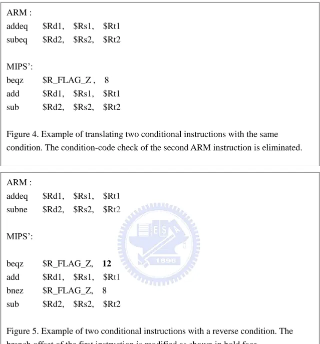
The code generator will check the next instruction to see whether the two instructions are under the same execution condition. Figure 4 shows one example of this optimization. In Figure 4, the baseline translation would generate four target instructions. However, since the two ARM instructions check the same condition code, our optimization can remove the second branch by modifying the target address of the first branch to skip over two instructions instead of one.
A similar optimization can be applied for two instructions having reversed condition codes. In this case, we may not eliminate the second check-condition instruction, but we can create a shorter execution path. The consecutive instructions with inverse condition codes implies that if the condition-code check of the first instruction fails, the condition-code check of the second instruction must be met, so that the offset of the condition branch for the first conditional execution instruction can be modified to bypass the second check. This is illustrated in Figure 5.
ARM : addeq $Rd1, $Rs1, $Rt1 subne $Rd2, $Rs2, $Rt2 MIPS’: beqz $R_FLAG_Z, 12 add $Rd1, $Rs1, $Rt1 bnez $R_FLAG_Z, 8 sub $Rd2, $Rs2, $Rt2
Figure 5. Example of two conditional instructions with a reverse condition. The branch offset of the first instruction is modified as shown in bold face.
ARM : addeq $Rd1, $Rs1, $Rt1 subeq $Rd2, $Rs2, $Rt2 MIPS’: beqz $R_FLAG_Z , 8 add $Rd1, $Rs1, $Rt1 sub $Rd2, $Rs2, $Rt2
Figure 4. Example of translating two conditional instructions with the same condition. The condition-code check of the second ARM instruction is eliminated.
3.3 Update condition flag selectively
Translating the update-condition-flags instructions will incur a high instruction overhead. For example, if we update all four condition flags for each instruction, the instruction overhead could be as high as 8 times (i.e. two additional instructions
generated per flag). It is one of the most critical areas that call for optimization.
In [1], the FX!32 translator deals with the same challenge since the x86 architecture has a similar condition-code architecture as ARM. FX!32 traces the condition code dependency in the control flow graph of each translated unit. A flag is not updated unless it is actually used. In other words, we try to locate those unnecessary flag updates, and avoid generating flag-updating instruction. For example, if instruction A updates all flags, and instruction B, which follows instruction A, also updates all the flags, then there is no need to translate the flag update for A, since no other instructions will use such updated flags from A. All the flag updates from instruction A will be overwritten by those from B. Through this analysis, we can selectively update the condition flags and eliminate most of the redundant updates to condition flags. As performed in FX!32, we also traverse successor blocks to further reduce unnecessary condition flag updates cross blocks. The performance impact of cross block redundant flag updates elimination is very significant.
3.4 Special condition code
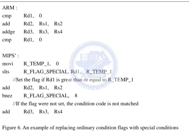
The previous two subsections deal with redundant condition check/update elimination. However, there are cases we must check/update the condition flags and the instruction overhead is high. These are cases where multiple condition flags need to be checked. For example, the GT condition indicates Z, N, and V flags must be checked. To avoid the cost of updating three flags, however, we could combine multiple condition-code check into one special condition to check. As illustrated in Figure 6, the check of the GE condition can be implemented with the set-less-than condition in MIPS’. In order to carry out this optimization, we must ensure there is only one type of check
ARM : cmp Rd1, 0 add Rd2, Rs1, Rs2 addge Rd3, Rs3, Rs4 cmp Rd1, 0 MIPS’ : movi R_TEMP_1, 0 slts R_FLAG_SPECIAL, Rd1, R_TEMP_1
//Set the flag if Rd1 is great than or equal to R_TEMP_1 add Rd2, Rs1, Rs2
bnez R_FLAG_SPECIAL, 8
//If the flag were not set, the condition code is not matched add Rd3, Rs3, Rs4
Figure 6. An example of replacing ordinary condition flags with special conditions flag.
between two condition code updates.
The multiple condition code update/check cases include HI, LS, GE, LT, GT, and LE. Since these six condition codes are set based on a less-than test, we can use only one set-less-than instruction to update the register allocated to represent the special condition code. This optimization reduces multiple condition bit updates and checks to only one update and check.
3.5 Combined conditional branch
ARM uses condition codes to carry out conditional branches. In some cases, while the MIPS’ only requires one compare-and-branch instruction, ARM may need two
to get the job done. Such cases include:
1) CMP + conditional branch 2) TST + conditional branch 3) TEQ + conditional branch
Although it seems that the cases above favor MIPS-like architectures, in practice, the advantage is not very significant. This is because the condition flags may be used in instructions other than the conditional branch, so the update of the condition flag cannot be eliminated.
Conditional branch optimization provides some interesting results on the translated EEMBC code. For some functions, the translated binary has even fewer target instructions than the source instructions. This is rather unusual when translating a more complex ISA (i.e. ARM) to a simpler ISA (i.e. MIPS’).
3.6 Other optimizations
The optimization methods introduced in the previous sections are part of the code generation components which work on the ARM’s IR. Optimizations at code generation time are rather limited since they do not have the knowledge of other instructions that have not yet been emitted. For example, the redundant condition code check elimination and the inverse condition check optimization are limited to consecutive instructions. More powerful optimizations can be implemented after the target IR’s are generated. For example, some classical local optimizations such as DCE (Dead Code Elimination), CSE (Common Sub-expression Elimination), CF (Constant Folding) and
CP (Constant Propagation and Copy Propagation) can be applied within a larger scope. Adding this phase of optimization may serve two purposes: 1) There may be optimization opportunities missed by the ARM compiler (which could be compiled with no optimizations) and 2) There may be new opportunities introduced during our binary code translation.
We have implemented a local optimization phase which identifies and reports on opportunities existing in the target IR’s. This phase also estimates the potential performance gain in terms of the number of instructions eliminated. This optimization phase is iterative. Based on profile analysis, we collect code patterns that may be optimized. Such patterns are given to the local optimization phase to identify and report on the complete set of benchmark. Based on the estimated performance gain, we set priorities on what transformations to implement first. The performance estimation of those local optimizations is discussed in Chapter 5.
Chapter 4 Simulation Environment
The target platform and the tool chain for our binary translation system are still under development. The processor chip has been under sampling and some test boards are available now. However, the evaluation of the performance of our binary translator is carried out with simulations where we could have hooks to collect more detailed profiles on benchmark execution.
4.1 Simulators
We have conducted both functional and performance simulations. For functional simulation, we have a MIPS’ simulator ported from SID [15]. SID is a simulator that supports multiple ISAs, and also provides support for testing, validation and debugging. We use a modified GDB 6.3 [16] to verify ARM binaries and collect profiles.
For performance simulation with micro-architecture details, we use the SimpleScalar ARM to measure the executed cycles. We also have a MIPS’ micro-architecture simulator to measure the performance of MIPS’ code. The configurations we used for ARM and MIPS’ are similar: for example, we assume a single issue, in-order processor with 32KB of I-cache and 32KB of D-cache. The MIPS’ has a deeper pipeline than the SimpleScalar ARM, but we assume both have the same clock frequency.
4.2 Benchmarks
The benchmark we use is the EEMBC [17] benchmark suite version 1.1. EEMBC benchmark is commonly used for embedded system developers to tune their hardware design and software tool chains. There are 55 programs and are divided into six categories: 8-16 bit, automotive, consumer, networking, office, and telecom. The EEMBC benchmark can be compiled as normal versions or as lite versions. To speed
up our simulations, we use the lite versions.
The ARM compiler we used to compile EEMBC is GCC 3.4.3 with static linking. To test our static translation comprehensively, we compiled the EEMBC benchmark with 3 different options: EEMBC-base, EEMBC-speed, and EEMBC-space. EEMBC-base is compiled with option “-O0”, EEMBC-speed is compiled with option “-O2”, and EEMBC-space is compiled with “-Os”. Since our translator does not translate the Thumb instruction set, we did not create versions with Thumb instructions.
Chapter 5 Experimental results
In this Chapter we evaluate the performance of the optimizations discussed in Chapter 3.
5.1 Baseline code generation
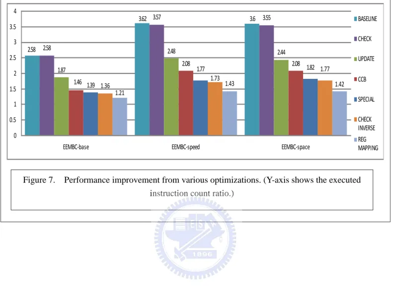
The performance improvements from each optimization discussed in Chapter 3 are presented in Figure 7. The baseline we used in comparison is the translated code using basic translations described in Chapter 2. The performance is measured by the ARM to MIPS’ execution ratio. For example, the performance of the baseline translation, which is labeled as “BASELINE” is 2.58 for EEMBC-base, 3.62 for EEMBC-speed, and 3.6 for EEMBC-space. The number, say 2.58, means the ratio of the dynamic number of executed MIPS’ instructions to the number of ARM instructions is 2.58. In other words, for each ARM instruction, on average, the basic translation would take 2.58 translated MIPS’ instruction to execute. The ratios are higher for optimized ARM binaries, 3.62 for EEMBC-speed and 3.6 for EEMBC-space. Optimized ARM binaries tend to have a higher translation ratio because compiler optimizations would have eliminated many simple instructions, such as the copy operation, which can often be translated into a single target instruction. The baseline ratio of 2.58 is somewhat expected based on past experience of binary translation of various general-purpose architectures.
The performance bar of each optimization is tagged with a name. For example, the bar for the optimization to eliminate redundant condition checks is labeled “CHECK”, and the performance bars for this optimization which eliminates unnecessary flag updates is labeled “UPDATE”. The optimizations are implemented in order, so the performance
gain is cumulative. For example, the performance gain of “UPDATE” includes the gain from “CHECK” and the “REG MAPPING” includes the gain attributed by all other optimizations.
5.2 Selectively check condition code
As shown in Table 3, a large fraction of instructions are conditional – they must check the condition code to determine if execution is needed. There are nearly 20% of such instructions in both EEMBC-speed and EEMBC-space. This indicates eliminating redundant condition checks may have a good potential for performance improvement when translating ARM binaries to other RISC architectures with no predicated execution instructions. Although it may be interesting to translate ARM instructions to Itanium architecture, which does have predicated instructions, there are no practical needs to do so because Itanium is not designed for embedded systems.
The bars under the name “CHECK” in Figure 7 are results from applying the redundant condition check elimination. Compared with the baseline translation, this optimization yields no gains for EEMBC-base, and small gains for both EEMBC-speed (from 3.62 to 3.57) and EEMBC-space (from 3.6 to 3.55). This seemingly low performance gain indicates that although conditional execution is frequent in ARM code, there are not many consecutive instructions using the same condition in the compiled EEMBC code. The frequency of using the same condition increased slightly when ARM binaries are optimized (i.e. in EEMBC-speed and EEMBC-space).
However, there is a different way to conduct redundant condition check elimination, which would require more complex data flow analysis and incur a much higher transformation cost. Notice that there may be instructions having the same condition as
execution predicates, but not next to each other. We can use a separate phase to search and group them together. For such a group, a single branch could skip the entire group. This is different from translating predicated instructions. For architectures with predicates, the analysis to determine if two instructions are under the same condition is easier – just check if the common predicate is updated between the two instructions. To determine whether two non-consecutive instructions are under the same execution conditions is a little more complex since multiple condition bits are involved. We are currently evaluating the potential for such an optimization.
5.3 Selectively update condition flag
Table 4 shows the percentage of instructions that may update condition flags in the origin ARM program. The percentage of instructions that update condition flags is almost as frequent as the instructions that check condition codes in the EEMBC-base. For EEMBC-speed and EEMBC-space, flag-update instructions are somewhat less frequent than conditional execution instructions.
The performance result of applying redundant condition update elimination is shown by the bars labeled as “UPDATE” in Figure 7. The ratio of EEMBC-base is decreased from 2.58 to 1.87, a 38% of performance improvement. The other two benchmarks have even higher improvements; the ratio is dropped from 3.57 to 2.48 for EEMBC-speed, a 44% of performance gain, and from 3.55 to 2.44 for EEMBC-space, with a 46% of performance gain. The redundant flag update elimination is the most significant optimization. When translating ARM binaries to other embedded architectures, this shall be the first optimization to consider.
flag updating is higher, thus the optimization yields a higher return.
5.4 Combined conditional branch
Combining condition code checking with a branch into a single compare-and-branch is a more interesting optimization discussed here. Most of the other optimizations eliminate redundancies introduced by binary code translation, but this combined conditional branch transformation not only eliminates redundancies but also compresses multiple instructions into one instruction. It gives our translator a chance (although small) to reduce the number of translated instructions executed to be even less than the number of source instructions.
The performance result of combined conditional branch is showed by the bars labeled as “CCB” in figure 7. All three benchmarks have very good improvement. Different from previous two optimizations, this optimization improves EEMBC-base more than the other two. The ratio of EEMBC-base decreased from 1.87 to 1.47, 27% of performance gain. For EEMBC-speed and EEMBC-space, the improvement is about 19%.
5.5 Special condition flag
Special condition flag optimization combines multiple condition updates and checks into one condition update and check, thus saving instruction overhead for flag updates and condition checks. In Figure 7, EEMBC-base has only slight improvement from this optimization (from 1.46 to 1.39, about 5% of gain), while EEMBC-speed and EEMBC-space have much greater speed up. The improvement for EEMBC-speed is about 18% (from 2.08 to 1.77) and 14% for EEMBC-space (from 2.08 to 1.82).
The check inverse condition code optimization has a minor impact to performance. All three benchmarks benefit 2-3% from this optimization. This should be no surprise to us because Section 5.2 indicates even the same condition optimization does not render notable performance gains. The approach that groups instructions with the same execution conditions (i.e. predicates) and use one branch for each group (as discussed in section 5.2) can also be applied here to enhance the reverse condition check optimization.
5.7 Register remapping
In the initial design, we allocated the four condition flags in one register, that is, a mapped register for CPSR. The flag checking and updating operations are carried out just like the ARM architecture. After learning the importance of flag emulation, we decided to keep each flag in a separate register to avoid instruction overhead to fetch/store the flag from/to the flag register.
In Figure 7, the bars with name “REGMAPPING” show the performance of this optimization. For EEMBC-base, the gain is about 12% (from 1.36 to 1.21), and the gain is more significant for the optimized ARM binaries. EEMBC-speed gains 21% (from 1.73 to 1.43) and EEMBC-space gains 25% (from 1.77 to 1.42).
With all above optimizations, the translated code can run at ratio 1.21 for EEMBC-base, 1.43 for EEMBC-speed, and 1.42 for EEMBC-space. The average ratio of the three benchmarks is 1.35. It is generally considered very cost-effective to get many applications ready for a new platform with only 35% of instruction path length overhead
2.58 3.62 3.6 2.58 3.57 3.55 1.87 2.48 2.44 1.46 2.08 2.08 1.39 1.77 1.82 1.36 1.73 1.77 1.21 1.43 1.42 0 0.5 1 1.5 2 2.5 3 3.5 4
EEMBC-base EEMBC-speed EEMBC-space
BASELINE CHECK UPDATE CCB SPECIAL CHECK INVERSE REG MAPPING
Figure 7. Performance improvement from various optimizations. (Y-axis shows the executed instruction count ratio.)
5.8 Local optimization estimation
As discussed in section 3.6, local optimizations such as DCE, CSE, CF and CP, may be applied to the target architecture IR’s after the code generation from the ARM IR’s. This is to exploit possible redundancy elimination opportunities introduced by the code translator. We implemented a local optimizer to identify such opportunities and estimate the potential contribution from such optimizations. Figure 8 shows the estimation – adding local optimizations may eliminate additional 5% of target instructions.
5.9 Cycle count of the benchmark
It might be unfair to compare the performance of translated code merely based on the instruction path length. For modern embedded processors, micro-architectures also play a very important role. In Figure 9, we compare the performance between ARM code and translated code using simulated execution cycles. As mentioned in section 4.1,
Figure 8: Estimation of the potential of local optimization (Blue bars: before local optimization; Red bars: after local optimization)
we use SimpleScalar ARM and the MIPS’ SID for cycle simulations. Although the SimpleScalar ARM simulator is easily accessible, its micro-architecture may not be ideal for implementing ARM processors because it first maps ARM instructions into micro-operations similar to modern Intel x86 implementations. Therefore, we select two configurations of SimpleScalar ARM to compare with our MIPS’ micro-architecture simulation. The first uses the default configuration for ARM, which we called DEFAULT. The second tries to make the simulated ARM compatible with our MIPS’ configuration, which we called COMPATIBLE. The configuration we used for our target MIPS’ is single issue, in-order execution, with separate 32KB I-cache and 32KB D-cache, and 35 cycle cache miss latency.
The measured cycle count ratios are shown in Figure 9. The DEFAULT ARM configuration yields an average CPI close to 1.45 for all three EEMBC benchmarks. Our simulated MIPS’ has an average CPI of 1.6. With the compatible setting, which forces the SimpleScalar ARM to issue one micro-operation per cycle, the average CPI of SimpleScalar ARM yields an average CPI close to 1.7. The total execution cycle ratio of MIPS’/DEFAULT becomes 1.31 (EEMBC-space), 1.53 (EEMBC-speed), and 1.53 (EEMBC-space). The total execution cycle ratio of MIPS’/COMPATIBLE becomes 1.10 (EEMBC-space), 1.30 (EEMBC-speed), and 1.31 (EEMBC-space).
5.10 Discussion on predicated execution and conditional
branches
In the EEMBC benchmark, there is one program where the translated code executes fewer instructions than the original ARM program. It is the rotate01_lite in the EEMBC-base benchmark, and the instruction ratio of ARM/MIPS’ is 0.94. The reason for a lower-than-1 ratio is because of the combined conditional branch transformation. The frequent use of conditional branches in this program provides our binary translator such an opportunity.
However, we notice that there could be other opportunities for our translator to yield lower-than-1 execution ratio for more programs. This is the case we mentioned in section 5.2. A conditional executed instruction is translated into a branch and a regular instruction, where the branch may skip the regular instruction. Although we may skip
Figure 9: comparison of the instruction count ratio and the cycle count ratio between the two architectures.
the regular instruction, we will have to execute the branch instruction so that the chance of reducing translated instruction is not obvious. Nevertheless, if we add a separate phase to group instructions with the same or reversed conditions together, we will have a greater opportunity to skip more instructions. In other words, programs with more “predicated false” instructions can have greater potential for our translated code to achieve a less-than-1 execution ratio.
Predicated execution will execute more instructions in general, but may minimize the cost of branch mis-predictions. Modern embedded processors may adopt deeper pipelines to achieve a higher clock rate (but must balance with power consideration), and increase the cost of branch mis-prediction. Our translated code does incur more branches as shown in Table 7. In Table 7, we can observe that the translated code, on average, have 4% more conditional branches in the executed instructions.
Conditional branch in ARM Conditional branch in MIPS’ EEMBC-base 7.86% 12.4% EEMBC-speed 11.4% 15% EEMBC-space 11.23% 14.8%
Table 7: Percentage of conditional branches in ARM binary and the MIPS’ binary.
Another consideration is the performance of the memory subsystem. Since our translation must keep the original ARM code, the executable will be at least twice as large as the original ARM binary. This, however, may not have a significant impact to the I-cache performance since most instruction accesses are from the translated code. The ARM code section is rarely referenced except for PC-relative data references, and when exceptions occur and the code must trap to the runtime system to get help from the
dynamic translator.
The primary purpose of a binary translation system is not for performance – it is to make more applications available at the time a new architecture is introduced. However, the performance and power efficiency gap should not be too severe to make the new embedded system attractive. With this in mind, our static translator, with code optimizations, can provide help to migrate application binary from ARM to other MIPS-like platforms.
5.11 Switch table lookup
The switch table lookup is used to accelerate the switch indirect branch, and a separate switch table is used to store all the potential switch target fields in ARM .text section. Unfortunately, the EEMBC benchmark suite rarely uses the switch statement, and the improvement by using switch table lookup is nearly zero. To show the power of the switch table lookup, we designed a new test program.
The program we tested contains a switch statement in a loop, and the switch targets are varied when the switch statement is executed. The loop runs about one million times, which minimizes the impact of startup code. Table 8 shows the result after we translate the ARM jump table into MIPS’ table. On average, the switch table lookup approach successfully reduced the instruction path length from 3.07 to 2.09. Almost one-third of the instructions in the original application are eliminated. Apparently, the switch table lookup is an effective way to handle indirect branches caused by switches.
I-Count Raio w/o switch table lookup
I-Count Raio with switch table lookup
Diff.
Base 2.159 1.571 0.588 Speed 3.654 2.385 1.269
Space 3.4 2.3 1.1 Avg. 3.071 2.085 0.986 Table 8. Instruction count ratio after applying switch table lookup
5.12 Comparison of code size
The code size is always an important issue for embedded systems, no matter it is static or dynamic code sizes. Larger static code size will requires more non-volatile storage. Lrager dynamic code size will demand for more memory, which is usually very limited in embedded systems.
Table 9 shows the comparison of the code sizes in ELF format, and both the ARM executable and MIPS’ executable are already stripped. The code size ratios in Table 9 show that the MIPS’ executable needs 80% more storage than the ARM executable.
ARM binary size MIPS’ binary size MIPS’ /ARM ratio Base 105422 183123 1.811
Speed 99415 170984 1.806 Space 99234 169941 1.803
Table 9: A comparison of the executable size of the source program and the target program
The .text section and the address mapping table are the two largest sections in the newly generated code. The comparison of the size of .text sections of the two programs is shown in Table 10. It shows that the MIPS’ .text section needs 70% more storage than the ARM .text section. The address mapping table section needs about 16KB to 32KB, which is about 11% of the average code size.
ARM .text size MIPS’ .text size MIPS’ /ARM Base 44174 75073 1.714
Speed 38537 68252 1.771 Space 38376 68152 1.775
![Figure 1. All 16 condition codes in the ARM architecture. N, Z, C, and V mean the respective condition bits are set.[18]](https://thumb-ap.123doks.com/thumbv2/9libinfo/7506554.117098/17.918.141.838.99.918/figure-condition-codes-arm-architecture-mean-respective-condition.webp)