國
立
交
通
大
學
電子工程學系
碩
士
論
文
無線通訊系統中具內容感知的視訊串流控制方法
Content-Aware Controls for Video Streaming in
Wireless Communication System
研 究 生:莊孝強
指導教授: 蔣迪豪 博士
黃經堯 博士
無線通訊系統中具內容感知的視訊串流控制方法
Content-Aware Controls for Video Streaming in Wireless
Communication System
研究生: 莊孝強
Student: Hsiao-Chiang Chuang
指導教授: 蔣迪豪
黃經堯
Advisors: Tihao Chiang
ChingYao Huang
國 立 交 通 大 學
電 子 工 程 學 系
碩 士 論 文
A Thesis
Submitted to Department of Electronics Engineering & Institute of Electronics College of Electrical Engineering and Computer Science
National Chiao Tung University in partial Fulfillment of the Requirements
for the Degree of Master of Science
in
Electronics Engineering
July 2004
HsinChu, Taiwan, Republic of China
無線通訊系統中具內容感知的視訊串流控制方法
蔣迪豪 博士
研究生: 莊孝強
指導教授:
黃經堯 博士
國立交通大學
電子工程學系 電子研究所碩士班
摘要
網際網路上的視訊串流技術已發展多年,其中多項壓縮、網路、及接收端
處理的技術,已經能夠讓使用者在視覺上得到良好的效果;然而,少有文
獻從端對端(end-to-end)的角度,探討無線網路中作視訊串流議題。本論
文的主要研究目的有二,一在於將通訊協定堆疊納入考量之下,觀察在無
線環境中作視訊串流,各項控制機制對於系統的影響。其二,由於頻寬的
變化會造成接收端緩衝缺空的問題,將嚴重損害使用者的接收品質。本論
文提出具內容感知的控制方法,此控制方法在解決緩衝缺空的同時,兼顧
了人類的視覺品質,讓整個視訊串流的過程中,使用者能夠得到平順的播
放品質。這項技術是基於 MPEG-4 漸進精細可調層次(Fine-Granularity
Scalability),作為資料的壓縮方式。此外,我們利用 ISO/IEC 21000-12
的測試平台(Test Bed)來評估這個控制演算法的實際視覺效果。為了驗證
這套控制方法可適用於無線通訊系統之中,我們開發了一個無線行動通訊
模擬平台,模擬在一般性的行動通訊架構之下,視訊串流內部的交互影響
流程。實驗的結果證明了所提出的控制方法可以在不影響系統容量的前提
之下,提供視訊串流的使用者,一個平順的播放過程。
Content-Aware Controls for Video Streaming in Wireless
Communication System
Dr. Tihao Chiang
Student: Hsiao-Chiang Chuang
Advisor:
Dr. ChingYao Huang
Department of Electronic Engineering &
Institute of Electronics
National Chiao Tung University
Abstract
Internet video streaming technologies have been developed for years, and
several techniques, located in the source coder, network nodes, and receiver
processing, can be used to achieve excellent visual quality for the clients. This
thesis proposes a content-aware control for video streaming in a wireless
cellular system such as cdma2000. The main purpose of this control scheme is
to provide uniform (smooth) quality video streaming over a wireless channel.
To provide a capability of rate adaptation, we adopt the MPEG-4
Fine-Granularity Scalability (FGS) scalable video coding technique as the
flexible format of the source bitstream. Besides, we utilize the ISO/IEC
21000-12 Multimedia Test Bed to evaluate the practical performance of the
proposed scheme. Furthermore, we develop the system-level simulation
environment to estimate the impact of the proposed control algorithm on a
wireless cellular system. The simulation result shows that appropriate control
is necessary for streaming video in the wireless communication system. The
proposed control technique provides a smooth playback for video streaming
application, while maintaining the system capacity unchanged.
誌謝
碩士班兩年的時光匆匆,似乎又到了離別的時刻。在人生最精華的兩年歲月裡, 感謝上天讓我有這個緣分遇見你們,陪我一起度過這段難忘的時光。 首先,我要感謝蔣迪豪老師以及王俊能學長,讓我有機會能夠參與 MPEG-21 Testbed 的發展計畫,因為參與這項計畫,學習到許多相關的知識及背景,為我日後論 文的完成紮下深厚的根基。同時要感謝的,是在我催生論文之時,像一盞明燈一直引 領著我的黃經堯老師。這篇論文許多關鍵性的問題,都是在和老師一次又一次的討論 之中,摸索找尋而得到了答案。感謝兩位老師總是要在百忙之中抽空,給予我適當的 方向及適時的指導,我才能順利完成這篇論文。 此外,我也要感謝家揚及耀中兩位學長,在和你們一起作計畫的過程中,向你們 學到不少東西,除了專業方面的知識之外,更有機會見識到強者我學長的行事作風, 讓我學習到如何能更有效率地處理事情,以及面臨難題時應有的態度。 另外要感謝的,就是在實驗室的日子裡,一起共同努力的伙伴們,耀諄、子良、 名彥、俊安、振韋、子翰、岳賢、汝芩、瑛姿、思浩,還有相處了五年的室友智勛、 志松。縱使一個人走在孤單的畢業之路上,因為有你們的陪伴,使我不再感到孤單, 這份心中的感動,對我而言,一定能夠成為畢生難忘的回憶。 最後,我要感謝我的家人,爸爸、媽媽、妹妹,和女友慧騏。因為你們在背後的 默默支持,這一路走來,總是可以感受到來自於你們的關心及祝福,讓我的心中充滿 著被關懷的溫暖。 能夠順利完成碩士論文,除了憑藉著自己的努力與決心之外,更因為有你們給我 的支持、鼓勵及陪伴,在論文趕稿的苦悶日子裡,我才能更加堅定不移地繼續走下去。 這篇論文,僅獻給最特別的你們。 莊孝強 謹誌 2004 年 7 月,Commlab,交大,新竹,台灣Contents
Chapter 1 Introduction ... 1
1.1 Overview of Multimedia Streaming over Wireless Network... 1
1.2 Motivation... 5
1.3 Overview of Video Coding Techniques ... 6
1.4 Overview of Adaptive Media Playout (AMP) Algorithm... 8
1.5 Thesis Organization ... 10
Chapter 2 Overview of MPEG-21 Resource Delivery Testbed and cdma2000 1x-RTT System...11
2.1 Overview of MPEG-21 Resource Delivery Testbed...11
2.1.1 Overall Architecture...11 2.1.2 Streaming Server... 12 2.1.3 Client... 16 2.1.4 Network Interface ... 18 2.1.5 Network Emulator... 19 2.1.6 Summary ... 20 2.2 cdma2000 1x-RTT System... 21 2.2.1 Layering Structure... 21 2.2.2 Framing Structure ... 25
Chapter 3 AMP-based Buffer Control for Scalable Video Streaming over cdma2000 1x-RTT System... 29
3.1 Components Definition... 29
3.1.1 Link-layer Components... 29
3.1.2 Components in OSI Layers 3~7... 30
3.2 Buffer Dynamics ... 32
3.2.1 Assumptions... 32
3.2.2 Fundamental Observations... 36
3.2.3 Mathematical Analysis... 41
3.3 Model-based Adaptive Media Playout (AMP)... 43
3.3.1 Probability Model for Buffer Control ... 44
3.3.2 Objective Visual Quality in Temporal Domain... 47
3.3.4 Summary...56
Chapter 4 Experimental Results ...57
4.1 Experimental Scenario Design ...57
4.2 Experimental Results...61
4.2.1 Comparison of Frame-rate Adjustment Schemes ...62
4.2.2 Performance of Pre-processing and Post-processing Tools...65
4.2.3 Summary...72
Chapter 5 Conclusion ...73
5.1 Contributions ...73
List of Figures
Figure 1-1. The evolution of data throughput from 2G to 3G wireless network ... 1
Figure 1-2. The general scenario for wireless multimedia streaming... 3
Figure 1-3. Illustration of the fine-grained and the layered scalability... 7
Figure 1-4. Generic structure for transmitting scalable-coded bitstream... 8
Figure 2-1. Overall architecture of the MPEG-21 Testbed ... 12
Figure 2-2. MPEG-4 FGS bitstream structure in terms of resynchronization markers ... 13
Figure 2-3. Representation of the bitstream segmentation for MPEG-4 FGS ... 14
Figure 2-4. Representation of typical leaky bucket model ... 16
Figure 2-5. Interaction among packet buffer, stream buffer, and decoder in Testbed... 18
Figure 2-6. Protocol stack in Testbed streaming system... 19
Figure 2-7. Architecture of NIST Net ... 20
Figure 2-8. Layering structure of the cdma2000 RTT system ... 22
Figure 2-9. Detailed representation of the MAC Layer components... 23
Figure 2-10. Framing structure of cdma2000 system with 20ms frame ... 27
Figure 2-11. Segmentation of IP packets into RLP frames ... 27
Figure 3-1. Link-layer buffering mechanism... 30
Figure 3-2. Representation of OSI protocol layers 3~7 for video streaming application... 31
Figure 3-3. Simplified scenario for MPEG-4 FGS-coded bitstream buffering... 31
Figure 3-4. Two rate controllers in the transmission path for video streaming application... 32
Figure 3-5. Markov-chain rate assignment for data transmission over air interface ... 34
Figure 3-6. Buffer fullness over time during the streaming process... 37
Figure 3-7. Probability of underflow vs. Buffer fullness... 38
Figure 3-8. Probabilities of underflow vs. Buffer fullness at various source rates (average departure rate) (a)30kbps (b) 40kbps (c) 50kbps (d) 60kbps (e) 70kbps (f) 80kbps ... 39
Figure 3-9. The impact of pre-roll time on the underflow ... 41
Figure 3-10. Simplified model for buffering ... 42
Figure 3-11. Approximation function for probability of buffer underflow... 44 Figure 3-12. CDF of approximation function for computing threshold of activating buffer
control algorithm ...45
Figure 3-13. Merge of two bounded random process...46
Figure 3-14. The segmentation used in estimating the distribution curve of buffer underflow47 Figure 3-15. The proposed architecture of buffer control mechanism ...49
Figure 3-16. Illustration of different observation time ...50
Figure 3-17. Flow chart of the proposed threshold adjustment...52
Figure 3-18. Distribution of various maximum departure rate at corresponding frame rate....53
Figure 3-19. Smooth adjustment of frame duration ...54
Figure 3-20. The proposed AMP-based buffer control mechanism ...56
Figure 4-1. Platform built for link-layer simulation of realistic video content ...58
Figure 4-2. An example of packet profile designed for the simulation platform ...58
Figure 4-3. Transceiving behavior of cdma2000 1x-RTT simulator ...59
Figure 4-4. Architecture of the prototyping system for visualization of AMP-based control algorithms ...60
Figure 4-5. Graphical user interface of the prototyping system for visualization of AMP-based control algorithm ...61
Figure 4-6. Illustration of linear frame-rate adjustment ...62
Figure 4-7. Mean discrepancy among various frame-rate adjustment schemes...63
Figure 4-8. Comparison of (a) long-term and (b) short term standard deviation among various frame-rate adjustment schemes...64
Figure 4-9. Comparison of underflow events among various frame-rate adjustment schemes65 Figure 4-10. The framework of the proposed control mechanism ...66
Figure 4-11. Comparison of mean discrepancies among various control scenarios...67
Figure 4-12. Comparison of underflow events among various control scenarios...68
Figure 4-13. Comparison of (a) long-term and (b) short-term standard deviation among various control scenarios ...69
Figure 4-14. Snapshots of the playback process for streaming video sequence “container”. The accompanying number is the associated frame number of each video frame. ...72
List of Tables
Table 2-1. F-FCH RS1 Modulation Parameters... 26
Table 2-2. F-SCH Modulation Parameters for Data Rates Derived from RS-1... 26
Table 3-1. Comparison of occupied percentage of protocol overhead on the channel throughput among various frame rates... 35
Table 3-2. Parameters that influence the probabilities of buffer outage ... 36
Table 3-3. Impact of threshold on visual quality ... 51
Chapter 1
Introduction
1.1
Overview of Multimedia Streaming over Wireless Network
The 3G wireless communication technology has been developed for years. The advantages of 3G wireless technologies over the former technologies can be described from either from the system or the end-user points of view. With better wireless techniques, including power control, soft handoff, transmit diversity, and turbo coding, we can further improve voice capacity, data throughput, and battery life. Among these advanced features, the capability of high data throughput enables several applications, such as web browsing, network games, background download of e-mails, files, and multimedia streaming. Figure 1-1 shows the evolution roadmap of the data throughput provided by a distinct wireless service network. Time division multiple access Global system for mobile communication Personal digital cellular CDMA One General packet radio service MC1x CDMA 2000 1xEV Wideband CDMA Enhanced data GSM environment 2G 9.6 – 14.4 Kbps 2G+ 64 – 144 Kbps 3G 384 Kbps – 2 Mbps Time division multiple access Global system for mobile communication Personal digital cellular CDMA One General packet radio service MC1x CDMA 2000 1xEV Wideband CDMA Enhanced data GSM environment 2G 9.6 – 14.4 Kbps 2G+ 64 – 144 Kbps 3G 384 Kbps – 2 Mbps
Figure 1-1. The evolution of data throughput from 2G to 3G wireless network [1]
However, these applications have diverse requirements with different parameters for wireless transmission. For example, web browsing requires the completeness of data while accessing the desired web page. Thus, the reliability of transmission is the key to this kind
of application. Take multimedia streaming for an example, most of the streaming service can tolerate the error in data integrity to some degree; instead, the delay issue is critically essential here because the multimedia data should be played back in a timely fashion. The 3G wireless technology such as [2] has defined different QoS classes with corresponding attributes to characterize the quality of service. In the QoS provisioning system, dissimilar types of data application could be of different importance, and hence more important applications could obtain higher priority to transmit with better quality, in terms of corresponding quality metrics.
Among all applications of multimedia transmission, one of most challenging services is the multimedia streaming (e.g. video/audio streaming or A/V simultaneous streaming). In the conventional multimedia streaming over the Internet, several issues such as bandwidth, delay, and loss are the key factors that influence the end-to-end performance. Besides, to transport multimedia data in a heterogeneous environment is also a challenging problem [3]. All-IP network architecture adopted by the future wireless data communication simplifies the heterogeneity problems. The existing protocols in OSI layer 4~7 could be efficiently re-used based on the IPv4 or IPv6 [4] network. Furthermore, some multimedia standards recommend that the specified applications should be transmitted at the IP-based network. For example, the real-time transmission of MPEG-4 streams should exploit the Real-time Transport Protocol (RTP) as the session-layer protocol, which is based on the User Datagram Protocol (UDP) at the transport layer and Internet Protocol (IP) at the network layer [5]. However, the heterogeneity problems still make the multimedia transmission difficult in term of terminal capabilities.
To provide good experience for each user, several control schemes, which could be categorized into congestion control and error control. The congestion control is used to reduce the packet loss and delay caused by network congestion. Usually, the connection path from the server to the client could be equivalently seemed as a virtual buffer. If the transmission traffic exceeds the available bandwidth, the residual parts of the traffic will be stored in the virtual buffer and wait to be sent to the destination in the following time slots. As the channel bandwidth varies with time, the resulting wait time would be changed respectively, and this causes the so-called delay/jitter problem. Once the amount of accumulated data is greater than the size of virtual buffer, the surplus data would be discarded, and this forms the major reason of the packet loss in the transmission over
Internet.
The packet loss is inevitable during the transmission of multimedia data, and the loss incurs different devastating effects such as quality degradation, decoding corruption, and out of synchronization. The purpose of error control is to mitigate the impairment caused by the packet loss. The error control could be done in two aspects: transport and compression layers [3]. The techniques such as retransmission and forward error correction (FEC) could be classified into the transport-based error control; while some post-processing schemes such as error resilient and error concealment belongs to the compression-domain error control.
As compared to the streaming over Internet, the multimedia streaming over wireless network suffers more limitations. One of the limitations primarily comes from the diverse nature between wire-line and wireless connection. Figure 1-2 illustrates a general scenario for multimedia streaming over wireless network. The associated protocol stacks are also shown in the lower part of the figure.
Figure 1-2. The general scenario for wireless multimedia streaming
We can see that multimedia streaming service requires not only the wireless connection between the mobile station (MS) and the base transceiver station (BTS) should be maintained, but the access to the Internet has also to be supported as well. The diversity of the Internet would much complicate the discussion of the multimedia streaming. In this
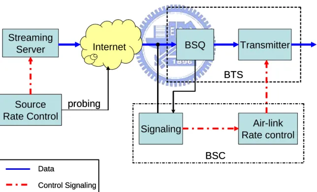
thesis, we focus on the last-mile transmission by assuming that the streaming server is located in front of the Packet Data Switch Network (PDSN). Without loss of generality, the terminology we use in this thesis is based on the cdma2000 1xEV-DO wireless network. Similar architecture appears in other wireless networks that support data transmission, such as GPRS and WCDMA. For example, the correspondence exists between the PSDN in cdma2000 1x system and the Serving / Gateway GPRS Support Node (SGSN/GGSN) in the WCDMA system, while both are interfaces to the packet data network.
The obstacles of wireless multimedia streaming are similar to the issue of streaming over Internet. In addition, the rapid variation of the wireless link quality, which is caused by fading, interference, and multi-path effect, makes the transmission environment more challenging. The bandwidth1 changes more rapidly, the round-trip delay becomes larger, as well as the probability of random packet loss increases. In the same way, the aforementioned techniques of error control and congestion control could be employed to combat against these detrimental effects. Nevertheless, the radio resource is a limiting factor for these control schemes in a wireless cellular system. A determination of a control algorithm may not be appropriate for the use of wireless streaming due to this additional restriction. Hence, the introduction of buffers is important to transmit data over a wireless network. There are often buffers located in the (Base Station Controller) BSC/ (Packet Control Function) PCF and the MS, respectively, to absorb the variation of rate either at the transmitter or receiver side. One of the most important issues this thesis address is the impact of buffers on the end-to-end performance for streaming over a wireless network as described in Chapter 3.
Another major difficulty for multimedia streaming is the maintenance of inter-stream (e.g. video, audio, subtitles…) synchronization [6]. A typical solution to this problem is to synchronize the time stamps of the associated streams using a master clock, such as Simple Network Time Protocol (SNTP) [7]. However, the clock drift between the server and client still cause problems in synchronization during a long duration transmission. This thesis studies the issue of video streaming only because the synchronization is within the scope of another research field. In the following sections, we focus the discussion on the video streaming and its related topics.
1.2
Motivation
For video streaming over wireless channel, there are limited literatures that address both the issues of source transmission and channel condition. Most of multimedia-related papers focus on the efficiency of the proposed technique on various types of hypothetical channels. On the other hand, majority of papers related to wireless communication discuss the end-to-end performance of different streaming architectures by assuming the distinct traffic model of the video streaming. This work addresses issues of both realistic source transmission and wireless channel. As to the source transmission, we adopt the MPEG-21 Testbed [8] as a realistic streaming server that packetizes each access unit of video bitstream into an IP packet. As to the transmission channel, we develop a cdma2000 1x-RTT based platform for simulating the air-link transmission of video content from the BTS to the MS. The realistic simulation of video streaming over wireless channel gives more valuable indication for a practical system design.
Due to the relatively rapid variation of physical channel for wireless communication, the effective transmission characteristics, such as available channel rate and error rate, also change quickly. The rapid variation of channel condition causes serious damage to the buffer in the receiving side, i.e., the outage (underflow and overflow) probability of buffer arises accordingly. Stockhammer et al. [9] explore the required pre-roll time and buffer size for video streaming via variable bit-rate wireless channels. They propose a buffer design by pre-determining the buffer size and pre-roll time for a specific bounded receiving process. However, the pre-determination of pre-roll time is inadequate for some streaming scenario, such as live-content streaming. Several channel-adaptive streaming techniques are proposed to solve this problem, such as Adaptive Media Playout (AMP), rate-distortion optimized packet scheduling, and channel-adaptive packet dependency control [10]. Among these techniques, the AMP could moderate the receiving buffer status without the involvement of the server, and this is a desirable feature since the manufacturer of a mobile station and the operator of cellular system are usually separated. Hence, the AMP-based buffer control is an attractive solution for the buffer outage during streaming in the modern cellular system.
However, an AMP-based buffer control causes noticeable artifact to the human perception, which is an undesirable side-effect of the buffer control. To this end, this wok aims to eliminate the quality degradation, which keeping the performance of buffer control.
1.3
Overview of Video Coding Techniques
For video streaming, there are principally two category of video coding technology that facilitates the transport of video content over IP-based networks. The first type is the non-scalable video coding scheme, which provides better coding efficiency but suffers more error-resilient problem in video streaming. Typical multimedia compression standards such as H.261, H.262 (also refers to MPEG-2), H.263 series (H.263 baseline, H.263+, H.263++), belongs to this category. Techniques such as pre-roll buffering and delay-constrained retransmission could be utilized to improve the error resiliency of the non-scalable coding scheme. Quaglia et al. [11] present an adaptive packet classification method to ensure the most important part of the bitstream could be transmitted to the client side, which also addresses the data integrity issue of the single layer coding scheme. To improve the rate adaptation capability of the non-scalable video, S-frame [12] and SP-frame [13] solution have been proposed to dynamically resolve the error-drift problem caused by the loss in the non-scalable bitstream. However, both these solutions suffer loss in coding efficiency to improve the bitstream robustness.
Real-time video encoding retains both the coding efficiency and the error resilience of the non-scalable coded bitstream for delivery video over network, provided that the feedback information for rate control is accurate enough. The source coder could dynamically adjust the coding rate by methods to increase/decrease the quantization step, retain/discard high-frequency Discrete Cosine Transform (DCT) coefficients, and increase/reduce frame rate. Nevertheless, the real-time encoding with adaptive rate control would increase the load of the streaming servers. Usually, each subscriber requires individual encoding thread to accommodate the corresponding network condition. Consequently, the solution of real-time encoding suffers complexity and cost problems, especially when the number of clients is large.
The second type of video coding scheme is the scalable video coding. There are usually three dimensions of the scalability, namely, SNR, temporal, and spatial. The layered scalable techniques given by the MPEG-2 coding standard provides stair-case rate adaptation capability [14]. Take SNR scalable coding as an example, higher visual quality could be obtained by receiving more layers of bitstream via the connection channel. However, the finite level of scalability limits the use of scalability in video streaming
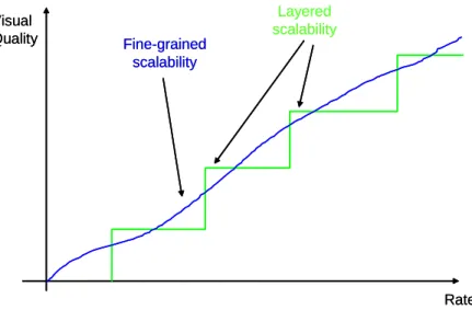
application. Hence, the MPEG-4 coding standard addressed this issue and proposed the Fine-Granularity Scalability (FGS) [15] to provide bit-level flexibility for the rate adaptation. Figure 1-3 illustrates the concept of the layered and the fine-grained scalability.
Rate Visual Quality Fine-grained scalability Layered scalability Rate Visual Quality Fine-grained scalability Layered scalability
Figure 1-3. Illustration of the fine-grained and the layered scalability
As we can see, the fine-grained scalability could provide better bandwidth utilization than the layered scalability. The layered scalability may sometimes outperform the fine-grained scalability due to the non-scalable nature of the layered bitstream, and hence the coding efficiency of the associated layer would be higher. Detail comparison between these two kinds of scalability is discussed in [16].
Another kind of scalable video coding is the multiple descriptions coding scheme (MDC) [17], which was designed for path-diversity network such as IP-based network. There is no priority among descriptions and the reconstructed quality is based on the number of received descriptions. Therefore, in the packet network with path diversity, this coding scheme can be efficient in delivery of coded stream. As compared to the traditional layered scalable video coding scheme, the MDC coding scheme outperforms the layered coding scheme when packets are transmitted with unequal importance. Conversely, the layered coding has more benefits than the MDC coding when the rate-distortion (R-D) optimized packet scheduling are employed [18]. Some literatures have addressed the issue of transmission of MDC coded stream via wireless networks, and this thesis would focus on the scalable coding with the fine-grained scalable coding scheme.
All these scalable coding techniques could be exploited to provide better error resiliency and bandwidth utilization. The major drawback of the scalable video coding is the
coding efficiency problem. In most cases, the MPEG-4 FGS encounters a 2~3 dB loss in PSNR (Peak SNR), compared to the non-scalable MPEG-4 simple-profile coding scheme, at the same bit rate [19]. The coding efficiency problems of the scalable coding scheme have been investigated for years, and recently, the MPEG committee is preparing to collect proposals [20] on the state-of-the-art scalable coding techniques into the advanced scalable video coding standard (MPEG-21 part 13: scalable video coding).
The generic structure of using the scalable video coding technique in video streaming technique is depicted in Figure 1-4. A transcoder performs rate control to calculate the target transmission rate, following a rate shaper to truncate the enhancement-layer bitstream into a proper size for transmission. The coded-scalable bitstream under consideration could be generated by any scalable video coding algorithm that supplies bit-level scalability. Without loss of generality, this thesis focuses on the scalable video streaming using the MPEG-4 FGS coding scheme over wireless network. Similar results could be derived from the conclusion of this thesis in case that the advanced scalable video coding owns the same features with MPEG-4 FGS.
Scalable-Coded Bitstream Rate Controller Rate Shaper Transcoder Transmitter Adapted Bitstream Scalable-Coded Bitstream Rate Controller Rate Shaper Transcoder Rate Controller Rate Shaper Transcoder Transmitter Adapted Bitstream
Figure 1-4. Generic structure for transmitting scalable-coded bitstream
To provide the capability of rate adaptation, in this thesis, we adopt MPEG-4 FGS as the scalable video coding scheme of interest, since the transcoding of FGS bitstream is relatively simple than other kinds of rate adaptation schemes. The scalable video coding is mainly used to adapt to the variation of effective channel bandwidth, i.e., the overall effect of channel throughput, including the channel bandwidth provided by the Internet and the cellular system.
1.4
Overview of Adaptive Media Playout (AMP) Algorithm
Adaptive Media Playout (AMP) is a receiver-based buffer control technique that adjusts the frame rate of the playback process, such that the probability for the event of buffer outage is minimized. Take buffer underflow for an example, the frozen picture
commonly seen causes serious damage to the perceptual quality, and the AMP scheme could prevent this situation by reasonably modulating the frame rate. Informal subjective tests have shown the reduction of playback rate up to 25% is unnoticeable [21]. Typically, the AMP-based buffer control could be divided into two steps. The first step is to determine the threshold for control activation. This step chooses a suitable threshold of buffer fullness to prevent potential buffer outage. The second step is to compute the playout rate based on the relationship between current buffer fullness and the predetermined threshold.
Yuang et al. [22] proposed a video smoother, which is based on a paradigm for threshold selection, and apply the selected threshold into an exponentially distributed service time to determine the next time for video frame play-out. With sets of fixed arrival-to-departure ratio, the effects of threshold selection on buffer outage are outlined. This paradigm of determining threshold gives some recommended threshold values for specified buffer outage parameters under the assumption of Poisson arrivals. The video smoother provides efficient buffer control, but it does not take the visual quality into account.
Laoutaris and Stavrakakis [23] address the issue of visual quality while supporting adaptive video playout. The receiving buffer is formulated as a M/G/1 queue and the buffer occupancy becomes a Markov chain. They merge the impact of buffer outage and buffer control into the proposed metric, Variance of Distortion of Playout (VDoP), to dynamically adjust the playout rate. Specifically, the control of playout rate is based on the threshold value determined by the dynamic threshold adjustment. An online detection algorithm for estimating optimal long-term value of threshold is proposed to provide a basis for the dynamic threshold adjustment. The value of threshold would be dynamically evaluated when the statistical behavior of arrival process is changed.
Kalman et al. gives an analytical result for various streaming environment such as archived streaming and live-content streaming [24]. The effect of packet retransmission, which is caused by the error-prone channel, is also included in the system model under consideration. Besides, the diverse delay-underflow tradeoffs for these streaming scenarios are also studied. This paper provides a sophisticated analysis on the channel model and the queuing model for client to clarify the relationship among pre-roll time, playout control, and buffer underflow. Experimental results show that significant performance improvements can be obtained in comparison to non-adaptive media playout.
Liang and Huang [25] proposed a content-based adaptive media player based on Perceived Motion Energy (PME), which implies the motion activity of a video sequence. They also proposed an AMP-based control in accordance with a distortion function, which combines both the distortion caused by control and the distortion incurred by the buffer outage. This control could provide better perceptual quality since the PME takes the motion activity into account.
This thesis proposed a model-based AMP control mechanism which addresses issues of both threshold and playout rate adjustments, which are based on the statistical assumption of both arrival and departure processes. The threshold and playout rates are computed to consider both the elimination of buffer outage and the smoothness of visual quality. The detail of the control algorithm will be stated in Section 3.3.
1.5
Thesis Organization
The organization of this thesis is described as follows:
Chapter 2 introduces the emulation platform of the MPEG-21 Resource Delivery Testbed, which is the basis of the experiment environment of this thesis. Some features of the Testbed are also qualified in this chapter.
Chapter 3 addresses the issue about wireless video streaming and states the architecture of the core control algorithm. The detail explanation of the proposed control scheme is included. A migration to the content-aware streaming will also be described in this chapter. Chapter 4 shows some experimental result based on the proposed control algorithm. Both the end-to-end and the system-level performances are presented to justify the efficiency of the proposed control scheme.
Chapter 2
Overview of MPEG-21 Resource Delivery Testbed
and cdma2000 1x-RTT System
This chapter introduces the architecture of the MPEG-21 resource delivery testbed, which is the emulation platform for the experiment shown in this thesis. Some characteristics such as buffer configuration, rate control, traffic shaping, and packetization, will also be discussed. Some standard features such as Real Time Streaming Protocol (RTSP) / Session Description Protocol (SDP) control protocol would be skimmed only, as these standard features would affect the end-to-end performance lightly. Besides, we will describe the some streaming-related features of cdma2000 1x-RTT (Radio Transmission Technology) mobile system in this chapter, including the frame error rate, physical channel (FCH and SCHs) assignments, RLP retransmission, and etc. The physical-layer parameters are synchronized with the usage of [26], and some assumptions are also set in the same fashion. The mixed traffic system environment is also built to perform the system-level simulation.
2.1
Overview of MPEG-21 Resource Delivery Testbed
This section gives an overview to the MPEG-21 resource delivery testbed (abbreviated Testbed in the following text). The overall architecture is firstly introduced, while each component is explained in a functional fashion. This section would not touch the detail implementation because the MPEG-21 resource delivery testbed is just one example of the existing streaming system. Common features such as packetization, rate control, and rate shaping, of the testbed will be described.
2.1.1 Overall Architecture
The overall architecture of the testbed is shown in Figure 2-1. There are four major components in this streaming system: server, client, network interface, and network emulator. The server plays the role of a normal web server that waits for subscription for
multimedia content. Also, the server performs some sender-based controls that provide better quality of service for users. The client could be any subscriber that can make a request to the server for subscription, i.e., using the same protocols for negotiation during the streaming. The network interface defined in Testbed is the session-layer interface that uses RTP/RTCP for the real-time delivery of the content. The network emulator is used to emulate a channel whose behavior could be specified using some parameters.
Media Database DIA Streamer QoS Decision Server Controller Packet Buffer IPMP Network Behavior Offline Media Encoder Digital Item Information (CDI, XDI) RTP/ RTCP RTSP Mux with SDP RTSP DeMux with terminal capability TCP UDP Control NISTNet NISTNet TCP UDP Media Channels (RTP, UDP) Control Channels (RTSP, TCP) Network Profile RTSP Mux with terminal capability RTSP DeMux with SDP RTP/ RTCP Stream Buffer Decoder Output Buffer QoS
Decision Retrans.Monitor
Client Controller IPMP Packet Buffer User Characteristics Server
Network Interface Network Interface Network Emulator Client Control Media Database DIA Streamer QoS Decision Server Controller Packet Buffer IPMP Network Behavior Offline Media Encoder Digital Item Information (CDI, XDI) RTP/ RTCP RTSP Mux with SDP RTSP DeMux with terminal capability TCP UDP Control NISTNet NISTNet TCP UDP Media Channels (RTP, UDP) Control Channels (RTSP, TCP) Network Profile RTSP Mux with terminal capability RTSP DeMux with SDP RTP/ RTCP Stream Buffer Decoder Output Buffer QoS
Decision Retrans.Monitor
Client Controller IPMP Packet Buffer User Characteristics Server
Network Interface Network Interface Network Emulator
Client
Control
Figure 2-1. Overall architecture of the MPEG-21 Testbed [8]
2.1.2 Streaming Server
There are currently five functional blocks in the streaming server of the Testbed system. They are media database, Digital Item Adaptation (DIA), Streamer, QoS decision, server controller. The media source is firstly encoded by the offline media encoder and archived in the storage. The coded bitstream will then be managed by the media database. The media database supports the segmentation of the media into resource unit (in the terminology of MPEG-21 standard). The segmented bitstream will then be retrieved by the DIA engine, which performs resource adaptation according to the external description (Content Description Item (CDI) and conteXt Description Item (XDI)) and both static and dynamic description could be resolved. For video, the resource adaptation refers to the rate control
and rate shaping of the scalable bitstream. The streamer is primarily in charge of sending the adapted resource in a smooth way. To this end, the embedded leaky-bucket traffic shaping algorithm is employed at the streamer. The details of the bitstream segmentation, resource adaptation, and traffic shaping, are explained as following sub-sections. The functionality of each functional block in the server side is stated as follows:
z Offline encoder:Compress the source sequence into scalable bitstream
z Media database:Manage coded bitstream and segment bitstream into video packets z DIA engine:Provide resource and description adaptation capability
z Streamer:Shape the transmission traffic in a smooth way
z QoS decision:Analytically compute the available transmission rate for each media
based on the estimation of available channel rates
Bitstream segmentation (Media Database)
Due to the direct access to the bitstream, media database could retrieve some embedded information by parsing bitstream. During encoding process, some resynchronization markers are inserted into the bitstream to improve the error resiliency. Figure 2-2 illustrates the MPEG-4 FGS bitstream structure in term of the wide-sense resynchronization marker (Video Object Planes (VOP) start code, bit-plane start code (BPSC), and resynchronization marker (RM)).
Sequence header VOP header RM RM VOP header
…
RM…
Base-Layer Bitstream Enhancement-Layer Bitstream Sequence header VOP header RM RM VOP header…
RM…
BP SC BP SC BP SC Sequence header VOP header RM RM VOP header…
RM…
Base-Layer Bitstream Enhancement-Layer Bitstream Sequence header VOP header RM RM VOP header…
RM…
BP SC BP SC BP SCFigure 2-2. MPEG-4 FGS bitstream structure in terms of resynchronization markers
The bitstream segmentation of the MPEG-4 FGS structure is recommended in [27]. This bitstream segmentation could prevent the start-code emulation (i.e., incorrectly recognize the received symbol as another existing symbol due to error) because it prohibits
wide-sense resynchronization marker from being packetized into separate packets. This efficiently improves the error resiliency and the ease of finding next synchronization point for decoding, in case that packet loss occurs. As to the MPEG-4 FGS bitstream structure, the corresponding segmentation is depicted in Figure 2-3. There are additional five types of segmentation in the enhancement-layer bitstream owing to the utilization of bit-plane start code. Those segmentations shown in Figure 2-3 would not suffer any start-code emulation problem even if the packet loss rate is high. Note that each segment mentioned here is not necessarily a RTP packet. However, in the implementation of Testbed, no adaptive packetization is exploited and hence each segment is mapped into one RTP packet.
VOP header VOP header (1) VOP header RM (2) RM RM (3) RM VOP header (4) VOP header BP SC (5) RM BP SC (6) BP SC BP SC (7) BP SC RM (8) BP SC VOP header (9)
Occur both in BL and EL Occurs in EL only VOP header VOP header (1) VOP header RM (2) RM RM (3) RM VOP header (4) VOP header BP SC (5) RM BP SC (6) BP SC BP SC (7) BP SC RM (8) BP SC VOP header (9)
Occur both in BL and EL Occurs in EL only
Figure 2-3. Representation of the bitstream segmentation for MPEG-4 FGS
Resource Adaptation (DIA engine)
The DIA performs resource adaptation based on the CDI and XDI descriptions. For video streaming, the XDI is generated according to the network profile to describe the available channel bandwidth in some time interval. The resulting XDI is fed into the DIA engine to do rate adaptation of the scalable-coded bitstream. The rate adaptation could be broken into two steps: rate control and rate shaping. The purpose of rate control is to compute the available bit budget for a resource unit (e.g. one VOP). The rate control for video is similar to that proposed in[28], which is based on a weighted average scheme. The
formula is shown as follows: sec sec sec ) ( ) ( B w P w I w w t R t R B P I vop vop + + ⋅ = (2.1)
Where R(t) is the available channel rate at time t, wVOP is the weighting factor of the
associated VOP type, and the Isec, Psec, and Bsec is the number of VOP for each type in this
second. The weighting factor wI, wP, and wB is set to 1, 1, and 0.6, respectively. The
advantage of this rate control algorithm lies in its low complexity. However, the resulting visual quality depends on the selection of weighting factors for each type of VOP, while the quality varies among different type of VOP. Furthermore, better visual quality may be archived by R-D optimizing the streaming sequence, but this may require additional computational and/or storage complexity.
The computed bit budget is conveyed into the rate shaping module for truncating the enhancement-layer bitstream. Note here that enhancement-layer bitstream could be arbitrarily byte-aligned truncated except the symbol emulation should be avoided. For example, the last byte of the last resource unit is “0x00” in HEX, while the next resource unit is started with a VOP start code (0x000001b6). Then the concatenated bitstream would be “0x00000001b6…”, and this is not a valid codeword in the MPEG-4 bitstream syntax.
Traffic shaping (Streamer)
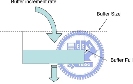
The major purpose of traffic shaping is to keep the transmission as smooth as possible, either in the rate or number of packet sense, depending on the structure of the underlying network. No apparent impact would appear when the transmission rate is low. However, the packet loss would be resulted when the traffic is high during some time interval, provided that traffic shaping algorithm is absent. If the transmission rate is high and no traffic shaping is used, the transmission duration may be relatively short, compared to the total transmission time. This would cause the instantaneous transmission rate exceeding the tolerable transmission rate of the underlying network. Intuitive solution to this problem is to evenly distribute the data in streaming over the total transmission time. Typical solution to this problem is to use either the “Leaky Bucket” or “Token Bucket” algorithm. The Testbed adopts the leaky bucket solution for traffic shaping, and the concept is illustrated in Figure 2-4.
of the protocol stack. The buffer is empty initially, and the transmission drives the data piling up into the buffer with a speed of transmission rate. Once the buffer fullness reaches to specific value, data begins to “leak” from the buffer with a speed of sustainable rate. With a fixed buffer size, a leaky bucket model could usually be characterized with three parameters: B (buffer size), R (leak rate), and F (initial buffer fullness). These three parameters determine the performance of a leaky bucket model for transporting data in a smooth way. To avoid buffer overflow, the buffer size or the leak rate should be large enough. In contrast, the buffer fullness and leak rate should also be adjusted appropriately to prevent buffer from going underflow.
Buffer Size
Leak rate = Sustainable traffic rate
Buffer Fullness Buffer increment rate
Buffer Size
Leak rate = Sustainable traffic rate
Buffer Fullness Buffer increment rate
Figure 2-4. Representation of typical leaky bucket model
2.1.3 Client
The ultimate goal of the client-side processing is to playback the desired content smoothly. However, the limited bandwidth and random error of channel complicate the processing for good reconstruction. The buffer is especially important because it mitigates the pain from synchronization and variation of receiving rate. The Testbed designs two buffers in the client side: packet buffer and stream buffer. The packet buffer is used to receive packets from the network interface, while the stream buffer provides additional protection to prevent packet buffer from going underflow or overflow. The decoder in the
Testbed is a MPEG-4 FGS compatible decoder with error-resilient capability, i.e., the decoder could continue to decode received bitstream even if the bitstream is corrupted by loss. The error control used in this Testbed is to use the NACK-based retransmission mechanism. The retransmission monitor checks the packet buffer for the lost packet in some frequency, say, one check per second, to record the sequence number of the lost packets. The lost record would be sent from the client to the server via reliable control channel, and the lost packets will then be retransmitted to the client. Besides, the decoder follows an output buffer to moderate the decoding speed and playback. The functionality of each component in the client side is summarized as follows:
z Packet buffer:Smooth out the fluctuation of receiving rate
z Stream buffer:Provide additional protection for packet buffer from going overflow or
underflow
z Decoder:Real-time decode the received bitstream with error-resilient capability
z Retransmission monitor : Monitor the packet-lost situation in the packet buffer
periodically
z Output buffer:Moderate the decoding speed for smooth playback
Buffer configuration
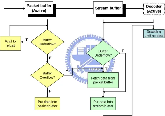
The packet buffer plays a role of receiver buffer that prevents packet reception from duplication and out-of order. In the perspective of rate, the buffer pair regulates the receiving rate, which is strongly correlated with the channel delay/jitter, into the transmission rate of the scalable-coded video clip for smooth decoding. Figure 2-5 shows the interaction among packet buffer, stream buffer, and decoder. The notation “active” used here indicates that the component would continuously and concurrently activate its functionality.
In a normal operation case, we could assume that there are data both in the packet buffer and stream buffer. The data rate input to this buffer configuration at time t is equal to the receiving rate, while the output data rate equals to the transmission rate at the time (t-∆), where ∆ is the pre-roll time. When the network condition is pretty good, the transmission rate is equal to the available channel rate. In this case, the packet buffer is easily overflowed due to the high receiving rate. The packet buffer would immediately put the surplus data (oldest in time) into the stream buffer for decoding, and no packet loss would be incurred.
On the other hand, the packet buffer would suffer underflow in case that the channel condition turns to poor. In this state, the decoder will continue to decode the data stored in the stream buffer even if there is no incoming data at the same time. While the network condition improves, the stream buffer could be refilled with the incoming packet data. Note that this buffer design is primarily to protect the buffer from going underflow, for two reasons. One is that there are more chances for buffer underflow because the unpredictable channel condition is usually poor. Second, the use of scalable coding scheme would not overflow the buffer; the play-out rate would be equal to the receiving rate provided that the available channel rate is always sufficient.
Buffer Underflow? Wait to reload Buffer Overflow?
Put data into packet buffer
Packet buffer
(Active) Stream buffer
Decoder (Active)
Buffer Underflow? Fetch data from
packet buffer
Decoding until no data
Put data into stream buffer T T T F F F Buffer Underflow? Wait to reload Buffer Overflow?
Put data into packet buffer
Packet buffer
(Active) Stream bufferStream buffer
Decoder (Active)
Buffer Underflow? Fetch data from
packet buffer
Decoding until no data
Put data into stream buffer T T T F F F
Figure 2-5. Interaction among packet buffer, stream buffer, and decoder in Testbed
2.1.4 Network Interface
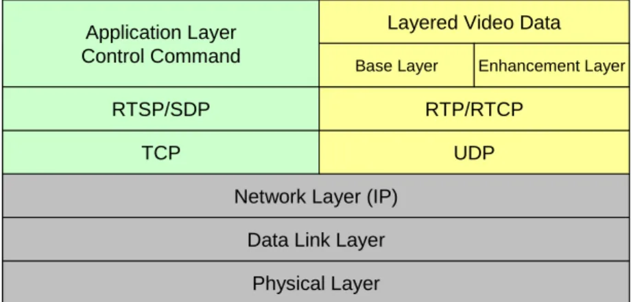
The network interface used in Testbed is mainly to encapsulate the resource units into RTP packets for transmission. For video, each adapted resource unit is retrieved from the DIA engine by streamer, will then be sent to the integrated packet buffer. The integrated packet buffer consists of the buffer storing the packet data for retransmission and the network interface that is used for packet delivery. Once a resource unit arrives the integrated
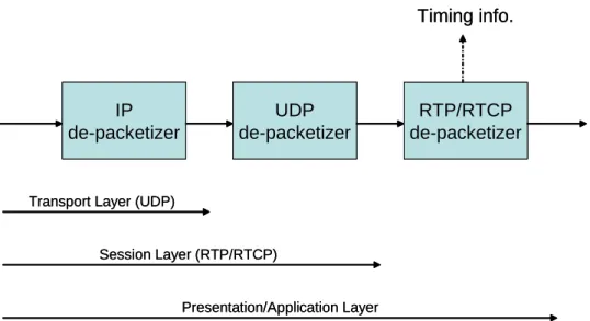
packet buffer, a RTP packetizer encapsulates the resource unit as a payload and appends the associated RTP header to the payload, forming a valid RTP packet for video content delivery. The detail description of a formal RTP packet could be found in [29]. Figure 2-6 shows the protocol stack used in Testbed system. The delivery of video data is via the RTP channel, which is based on the best-effort UDP network without proving reliability. As we mentioned in Section 2.1.3, the error caused by packet loss would be recovered by retransmission request from the client to the server side. To make sure the retransmission request could be correctly delivered to the server side, the RTSP messaging is through the reliable TCP channel because the traffic used for retransmission is minor. Note that the retransmission may sometimes fail due to the timing constraint of continuous playback, i.e., retransmission of a packet takes effect only if the packet arrives before it is consumed for playback.
Physical Layer Data Link Layer Network Layer (IP)
TCP UDP
RTP/RTCP RTSP/SDP
Application Layer Control Command
Layered Video Data
Base Layer Enhancement Layer
Physical Layer Data Link Layer Network Layer (IP)
TCP UDP
RTP/RTCP RTSP/SDP
Application Layer Control Command
Layered Video Data
Base Layer Enhancement Layer
Figure 2-6. Protocol stack in Testbed streaming system
2.1.5 Network Emulator
The principal use of the network emulator is to produce a heterogeneous channel environment that a streaming server-client pair would often experience. The Testbed adopts a Linux-based, public domain network emulator named NIST Net, which is developed by the National Institute of Standard Technology, of the United States. In addition to the supply of heterogeneous channel environment, the controllable channel parameter is another significant feature such that the users could create their own characterized channel. Controllable parameters comprise the bandwidth, random packet loss probability, delay, jitter, and size of network queue. Users could adjust these parameters using a text file-based
network profile, and the minimum time interval between two consecutive parameter settings are set to 1 second.
The architecture of the NIST Net is illustrated in Figure 2-7. The logical operation that NIST Net performs is described in the following [30]. Once a packet reaches the computer installed NIST Net, a packet intercept code would activate and seize control of the IP packet type handler. All IP packets received by network device will be directly passed to the NIST Net module. Packet matching determines whether and how an incoming IP packet should be processed by the packet processing, which includes drop, duplication, and delay, of a packet. The processed packet will then be transferred to the Linux IP level code. The fast timer takes control of system real time clock and uses it as a timer source for scheduling delayed packets. The fast timer reprograms the clock to interrupt at a sufficiently high rate for precise delay processing to a packet.
Figure 2-7. Architecture of NIST Net [30]
2.1.6 Summary
This section introduces the main architecture and operation of each functional block in the MPEG-21 Testbed resource delivery system. The Testbed is a real streaming system that users could create their own video content and deliver it over network. Some messaging mechanism, which would not significantly influence to the end-to-end performance, is touched on lightly. Besides, the network parameters are controllable, and the parameters
could be specified by network profile that is generated by any underlying network (both wire-line and wireless).
2.2
cdma2000 1x-RTT System
The wireless standards often cover large range of technical description that distributed both in the physical layer and the data-link layer. Nevertheless, this thesis aims at the video data transmission over this underlying network, especially for the streaming application of the scalable video stream. In this regard, we will discuss the layering structure of the cdma2000 1x-RTT system, and we would explain the impact of physical-layer attributes on the upper-layer parameters. The term “1x” defined here indicates the single carrier is utilized in the system deployment. The bandwidth variation could be directly derived from the rate assignment of the system, i.e., how many Supplementary Channels (SCHs) are assigned to a data user. In addition, the upper-layer packet loss probability could be computed from the frame error rate of the wireless link, by mapping the upper-layer packet into lower-layer frames. Furthermore, the delay and jitter caused by the wireless transmission could also be obtained from the frame error rate and the number of associated Radio Link Protocol (RLP) retransmission. The affect of lower-layer control such as power control would also be combined into the effect of the Medium Access Control (MAC).
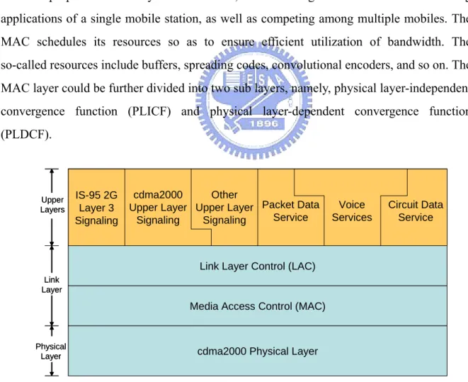
2.2.1 Layering Structure
The cdma2000 standard [31] mainly defines the technology details of the link layer and physical layer. The 1x-RTT provides a flexible framework to be the foundation of other ISO/OSI upper layers (network layer, transport layer, session layer, presentation layer, and application layer). Figure 2-8 depicts the layering structure of the cdma2000 RTT in the abstract level. The link layer aims to support control mechanism and protocol interfaces for data services. Another important use of the link layer is to map the logical channels, including the signaling channel and the data channel, into the coding and modulation functions of the physical layer. To support services in cdma2000 (especially for data services), link-layer protocols could be further divided into two sub layers, consisting of
LAC layer and MAC layer, as shown in Figure 2-8.
Link Access Control layer
The function of LAC layer is to ensure that various types of traffic are transferred over the air interface according to their QoS requirements. This purpose is achieved by making use of ARQ-based protocols, such as ACK/NACK and sequence-numbering retransmission, to support different level of reliabilities. The degree of error-free guarantee could be made higher at the expense of added delay. Note that for services like circuit-switched voice, the LAC could be a null-functional block.
Media Access Control layer
The purpose of MAC layer is two-folded; one is to mitigate the contention issue among applications of a single mobile station, as well as competing among multiple mobiles. The MAC schedules its resources so as to ensure efficient utilization of bandwidth. The so-called resources include buffers, spreading codes, convolutional encoders, and so on. The MAC layer could be further divided into two sub layers, namely, physical layer-independent convergence function (PLICF) and physical layer-dependent convergence function (PLDCF). IS-95 2G Layer 3 Signaling cdma2000 Upper Layer Signaling Other Upper Layer Signaling Packet Data Service Voice Services Circuit Data Service
Link Layer Control (LAC)
Media Access Control (MAC)
cdma2000 Physical Layer
Link Layer Physical Layer Upper Layers IS-95 2G Layer 3 Signaling cdma2000 Upper Layer Signaling Other Upper Layer Signaling Packet Data Service Voice Services Circuit Data Service IS-95 2G Layer 3 Signaling cdma2000 Upper Layer Signaling Other Upper Layer Signaling Packet Data Service Voice Services Circuit Data Service
Link Layer Control (LAC)
Media Access Control (MAC)
cdma2000 Physical Layer
Link Layer Physical Layer Upper Layers
Upper Layer Entities
LAC Sublayer
PLICF for MAC Instance 1 (e.g., Signaling)
PLDCF Mux and QoS Sublayer
PLICF for MAC Instance 2 (e.g., Packet Data Service) PLDCF Specific to
Instance 1
PLDCF Specific to Instance 2
CDMA 2000 1x-RTT Physical Layer Upper Layer Entities
LAC Sublayer
PLICF for MAC Instance 1 (e.g., Signaling)
PLDCF Mux and QoS Sublayer
PLICF for MAC Instance 2 (e.g., Packet Data Service) PLDCF Specific to
Instance 1
PLDCF Specific to Instance 2
CDMA 2000 1x-RTT Physical Layer
Figure 2-9. Detailed representation of the MAC Layer components
Physical Layer Independent Convergence Function (PLICF)
The PLICF is a component of the MAC layer that incorporates all MAC operational procedures and functions that are not unique to the Physical Layer. The PLDCF provides services to implement the actual communication activities in support of MAC layer service. The services that the PLICF uses are defined as a set of logical channels that carry various types of control or data information. Note that these logical channels do not map in a one-to-one manner to the physical channels in the Physical Layer. At a conceptual level, the PLICF can be integrated with any air interface by providing the appropriate PLDCF for that Physical layer. Examples of PLICFs that are defined for cdma2000 include Signaling PLICF, Packet Data PLICF, and Circuit Data PLICF.
Physical Layer Dependent Convergence Function (PLDCF)
The PLDCF performs three basic functions as follows. First, the PLDCF maps logical channels from the PLICF to the logical channels supported by the specific Physical Layer. Second, it performs multiplexing, de-multiplexing, and consolidation of control information with bearer data from the control and traffic channels from multiple PLICF instances in the same mobile station. Third, it implements the QoS capabilities, including the resolution of priorities among competing PLICFs (or mobile stations), and mapping of QoS requests
from PLICF instances into the appropriate Physical Layer service requests to deliver the desired QoS. The functions described above could be further divided into two sub-layers of the PLDCF. The Instance Specific PLDCF performs the first function, and the PLDCF MUX and QoS Sub-layer performs the last two functions.
The Instance Specific PLDCF
This sub-layer performs any required mapping of the simpler logical channels from the PLICF into the logical channels supported by Physical Layer. Besides, a more important feature is to provide any ARQ protocol that is Physical-Layer dependent and inappropriate for the LAC Sublayer to perform. For cdma2000, four PLDCF Non-reliable ARQ protocols are defined:
z Radio Link Protocol (RLP) – provides a highly efficient streaming service that makes a best effort to deliver data between peer PLICF entities. RLP supports both a transparent and a non-transparent mode of operation. In the non-transparent mode, RLP uses ARQ protocols to retransmit the missing data segment that were not delivered properly by the Physical Layer, and this mode may introduce some transmission delay. In the transparent mode, RLP does not retransmit the lost data segment but maintain byte synchronization between the sender and receiver and notify the receiver of the missing portions of the data stream.
z Radio Burst Protocol (RBP) – provides a mechanism for delivering relatively short data segments with best effort delivery over a shared access Common Traffic Channel. This capability is useful for delivering small amount of data without incurring the overhead of establishing a Dedicated Traffic Channel.
z Signaling Radio Link Protocol (SRLP) – provides a best effort streaming service for signaling information analogous to RLP, but optimized for the Dedicated Signaling Channel
z Signaling Radio Burst Protocol (SRBP) – provides a mechanism for delivering signaling messages with best effort delivery analogous to RBP, but optimized for signaling information and the Common Signaling Channel.
The PLDCF MUX and QoS Sublayer
de-multiplexing of code channels from multiple PLICF instances and implements QoS differences between those instances. This sub-layer also maps the data stream and control information onto multiple logical channels from different PLICF instances into requests for logical channels, resources, and control information from the Physical Layer. The PLDCF MUX and QoS Sublayer contain the following mapping functionalities:
z Functions that combine (and separate) traffic and/or control data on logical channels from multiple PLICF instances into (and from) logical channels supported by the Physical Layer.
z Three special Multiplexing/De-multiplexing Functions that perform the lowest level combination (separation) of logical traffic and signaling channel information into (from) physical channels that correspond directly to the code channels that the Physical Layer encodes and modulates (demodulates and decodes).
This sub-layer also provides the following QoS control functions:
z Consolidation of QoS requests from PLICF instances and maps the aggregated QoS requirement into the appropriate Physical Layer resource requests.
z Reconciliation of competing requests among mobile station in the base station.
z Coordination of the mapping and multiplexing/de-multiplexing functions in the PLDCF MUX and QoS Sublayer to deliver committed QoS to PLICF.
Note that the global management of QoS for cdma2000 system is anticipated to be accomplished using Upper Layer Protocols such as ReSerVation Protocol (RSVP). The PLDCF MUX and QoS Sublayer are designed to provide control interfaces and functional capabilities that effectively deliver the associated QoS requirement of Upper Layer Protocols.
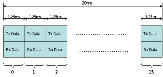
2.2.2 Framing Structure
The cdma2000 system supports frame structures of 20ms and 5ms. The 20ms frame is mainly used for Fundamental Channel, Supplemental Channel, and Dedicated Control Channel. The Dedicated Control Channel is also provided by the 5ms frame in both Forward Link and Reverse Link. For a 20ms frame structure, 16 pairs of time slots (1.25 ms
per slot) have been allocated for transmission and reception. Figure 2-10 shows the framing structure of the cdma2000 with 20ms frame for a base station.
This framing structure could support various transmission rates for each RLP frame, by differentiating the modulation parameters. For video streaming application over cdma2000 1x RTT system, the Forward Fundamental Channel (F-FCH) and Forward Supplemental Channel (F-SCH) would be often utilized for high-speed data transmission. Table 2-1 and Table 2-2 show possible sets of modulation parameters to support various information rates (encoder input rates) for cdma2000 1xRTT Rate Set 1(RS1) F-FCH and F-SCH, respectively. We adopt the 9.6kbps F-FCH as the fundamental channel of interest. Note that the higher amount of data a RLP frame carries, the higher average frame error rate would be in each frame since less data redundancy could be used for error correction.
Table 2-1. F-FCH RS1 Modulation Parameters [31] Data Rate (bps)
Parameter 9600 4800 2700 1500 Units
PN Chip Rate 1.2288 1.2288 1.2288 1.2288 Mcps
Modulation Symbol Rate 9600 9600 9600 9600 Sps
Walsh Length 128 128 128 128 PN Chips/Modulation
Symbol Processing Gain 128 256 455.1 819.2 PN chips/bit
Table 2-2. F-SCH Modulation Parameters for Data Rates Derived from RS-1 [31] Chip Rate (Mcps) Information Bits per Frame Encoder Input Rate(kbps)
Code Rate Puncturing Modulation Symbol Rate (ksps) Walsh Code Length 1.2288 168 9.6 1/2 None 9.6 128 360 19.2 1/2 None 19.2 64 744 38.4 1/2 None 38.4 32 1512 76.8 1/2 None 76.8 16 3048 153.6 1/2 None 153.6 8 6120 307.2 1/2 None 307.2 4
Tx Data 1.25ms Rx Data 0 1 15
………
………
20ms Tx Data Rx Data Tx Data Rx Data Tx Data Rx Data 2 1.25ms 1.25ms 1.25ms Tx Data 1.25ms Rx Data 0 1 15………
………
20ms Tx Data Rx Data Tx Data Rx Data Tx Data Rx Data 2 1.25ms 1.25ms 1.25ms1.25ms 1.25ms1.25msFigure 2-10. Framing structure of cdma2000 system with 20ms frame
For IP-based video streaming over cdma2000 1x-RTT system, each IP packet would be segmented into various number of RLP frames for transmission over the air link, depending on the IP packet size and the rate assignment for each RLP frame. Figure 2-11 shows this mapping relationship. Note that each IP packet would be segmented into an integer number of RLP frames. For each RLP frame, stuffing bits would often be inserted to the last RLP frame of an IP packet. One major reason for this mapping is to ensure the error resiliency in case that a comprised RLP frame is lost. However, stuffing bits would occupy available channel bandwidth and hence the effective transmission rate could be reduced.
IP packet 1 RLP 1 RLP 2 RLP 3 RLP 4 IP packet 2 RLP 1 RLP 2 RLP 3 RLP 4 RLP 5 Network Layer Link Layer IP packet 1 RLP 1 RLP 2 RLP 3 RLP 4 IP packet 1 RLP 1 RLP 2 RLP 3 RLP 4 IP packet 2 RLP 1 RLP 2 RLP 3 RLP 4 RLP 5 IP packet 2 RLP 1 RLP 2 RLP 3 RLP 4 RLP 5 Network Layer Link Layer
For 20-ms RLP frames, the number of RLP frames per second is fifty. This implies that the maximum number of IP packets per second should not exceed fifty due to the limitation of available slots. Typically, for low-rate streaming, one video packet would contain one video frame (to reduce the waste on protocol overhead). Hence, the number of packets are approximately twice to the video frame rate due to the use of two-layer bitstream structure of MPEG-4 FGS coding. Adaptive packetization of source bitstream would be relatively important in streaming scenario of interest.
Once the channel error arises, the number of packet should be increased to scatter the loss of bitstream for the ease of post-processing in the client decoder (e.g. error resilient and error concealment decoding). Despite the increase of protocol overhead, the associated framing structure could only tolerate limited number of IP packets to be transmitted through the air link. The exceeding number of IP packet would cause larger end-to-end delay, because the framing structure could not handle the surplus packet within a specific time period. This gives another constraint for adaptive packetization to transmit video content in the IP-based scenario.
![Figure 1-1. The evolution of data throughput from 2G to 3G wireless network [1]](https://thumb-ap.123doks.com/thumbv2/9libinfo/8597767.189994/13.892.129.802.461.955/figure-evolution-data-throughput-g-g-wireless-network.webp)
![Table 2-2. F-SCH Modulation Parameters for Data Rates Derived from RS-1 [31]](https://thumb-ap.123doks.com/thumbv2/9libinfo/8597767.189994/38.892.91.770.843.1146/table-sch-modulation-parameters-data-rates-derived-rs.webp)