Automatic Camera Calibration and Model
Reconstruction Using Multi-View Stereo
Liang-Chun Lin
∗, Ying-Jui Chen
∗, Xiang-Tao Wu
∗and Yi-Ping Hung
∗† ∗ Department of Computer Science and Information Engineering, National Taiwan University† Graduate Institute of Networking and Multimedia, National Taiwan University
Abstract—In this paper, we propose a method for
automatic camera calibration and model reconstruction from image sequences. Our camera calibration method is based on the recent works of structure from motion that recover camera motions via a set of corresponding feature points extracted from images. The refinement of camera parameters is achieved by exploiting the concept of silhouette coherence. Eventually, a modified volumetric graph-cut algorithm is used for model reconstruction from the set of calibrated images. We use an occlusion robust photo-consistency metric, which does not require geometric heuristics about the object, to seek the optimal surface that captures the concavities. At the same time, a set of surface points identified from silhouettes are enforced as hard constraints to preserve protrusions.
The camera calibration results of the proposed method are comparable to that of manual calibration even on real data, and the results of model reconstruction are also satisfactory. Since our method does not require images being calibrated in advance, it is suitable for digital archives and virtual exhibition of museum artifacts.
Index Terms—Structure from Motion, Visual Hull,
Volumetric Graph-Cut, Silhouette Coherence, Photo-Consistency
I. INTRODUCTION
Recently, constructing geometric models directly from photographs has received more and more inter-est in computer vision community. It is particularly suitable for acquisition of high quality 3D models of museum artifacts, which can be used in digital archives and 3D visualization for user interaction without physical access, such as applying virtual reality on museum exhibition [18][6][5].
However, manual camera calibration is not trivial in the model acquisition pipeline. It is especially tedious when calibrating a large set of images. As a result, an automatic camera calibration is essential. The motivation of our work is thus to reconstruct models from a set of uncalibrated images.
Among all the available camera calibration tech-niques, point-based methods are the most popular. But the dependence upon the presence of distinc-tive feature points on the object surface makes the calibration results inaccurate for objects with regular patterns or absence of texture. An alternative approach is to use the object outlines or silhouettes as the criterion of camera calibration when feature points are unavailable or unreliable.
Since mid-seventies there have already been image-based modeling methods that compute a coarse shape of an object from its silhouettes di-rectly [21][22][12], such as the visual hull intro-duced by Baumgart [2]. Silhouettes are often as-sumed or required as input by many multi-view stereo algorithms in order to reconstruct a visual hull that serves as an initial estimate of the scene geometry. We adhere to this assumption that sil-houettes are available and take advantages of both point-based and silhouette-based methods in our automatic camera calibration procedure. The cam-era parameters are estimated with an incremental structure from motion framework and then refined by a silhouette coherence optimization process.
After we have obtained a set of self-calibrated images, the 3D model reconstruction is the task of our concern. To pursue details on the object surface, color or texture consistency among different views is usually used as a measure for evaluating the visual compatibility within the input images. Multi-view stereo reconstruction can be formulated as an optimization problem with the photo-consistency measure defined as the cost function, algorithms such as graph-cut can be used to obtain global opti-mal solution [34][35]. Photo-consistency measures alone, however, are usually insufficient to preserve protrusion on the object surface due to the tendency
of graph-cut for shorter pathes, and hence some constraints can be enforced in the optimization to prevent over-carving [34][32][13]. We propose a simple method to identify from silhouettes a set of points which are believed to lie on the object surface and constrain the reconstructed surface to pass through or close to these points.
The remainder of this paper is organized as fol-lows. In Section II we review the related work. Sec-tion III describes our approach for camera calibra-tion and model reconstruccalibra-tion. Experimental results are shown in Section IV, and Section V concludes this work.
II. RELATEDWORK
There are two main categories of works related to ours: camera calibration and multi-view stereo.
A. Camera Calibration
Among all automatic camera calibration tech-niques, point-based methods are the most popular since they can provide accurate estimation results when feature points on the object surfaces are available and reliable. They typically utilize the correspondences of features such as corner points among images. One approach aims to recover cam-era parameters and sparse 3D scene geometry from image sequences is well known as structure from motion (SfM).
Snavely et al. [31] presented a SfM procedure to automatically compute viewpoints for a collection of photographs and a set of scene points at the same time. The proposed method takes an incremental approach that adds cameras into the optimization process one at a time to avoid getting stuck at bad local minima, which is similar to that of Brown and Lowe [3] with several improvements and has been proved to be robust over a variety of real-world images from Internet.
However, point-based methods may fail when dealing with textureless objects or man-made ar-tifacts whose feature points are not reliable. An alternative way is to adopt the silhouette-based methods which use the object outlines or silhouettes. Hern´andez et al. [17] introduced the concept of silhouette coherence, which exploits all information contained in the contours of silhouettes and can
be considered as a generalization of the epipolar tangency constraints [28][9].
For the two categories each has its advantages, we would like to incorporate both of them into our calibration procedure.
B. Multi-View Stereo
There are numbers of promising multi-view stereo techniques with capability to recover dense 3D models from calibrated images [29]. According to the representation of scene geometry, they can simply be categorized into two main categories: (1) algorithms that recover individual depth map for each image, and (2) algorithms that use a volumetric representation of shape.
In the first category, a reference image is selected and the corresponding depth map is constructed by assigning a disparity or depth value to each pixel. This kind of image-based representation is convenient particularly for smaller data sets, but a further process to merge multiple depth maps into a single mesh is necessary to capture the complete geometry.
The second category contains methods that rep-resent the volume directly. The visual hull, first introduced by Baumgart in his PhD thesis [2], is a classical reconstruction technique. The basic concept is to create a 3D representation of an object by its silhouettes within several images from dif-ferent viewpoints. However, it is unable to capture concavities on the object surface and can only be an approximation of the object’s geometry.
Vogiatzis et al.[34] proposed an inspiring ap-proach that poses multi-view stereo reconstruction as a 3D segmentation problem which aims to op-timally partition the space into ”foreground” and ”background”. A volumetric graph-cut algorithm with a continuous photo-consistency function de-fined on the surfaces is then used to seek the globally optimal solution. Since graph-cut prefers shorter cut, an inflationary term is added to the optimization procedure to prevent over-carving. The approach was improved later with a robust shape-independent scheme which treats occluded pixels as outliers when commuting photo-consistency for each scene point [35].
Nevertheless, a uniform ballooning term does not guarantee exact silhouette consistency. An
al-Fig. 1. System Overview
ternative way is to enforce silhouette consistency constraints in graph-cut algorithm. Specifically, the reconstructed shape when reprojected must coin-cide with the corresponding silhouette. Sinha and Pollefeys [30] used a complicated graph structure to reconstruct surfaces that exactly satisfies all the silhouette constraints while maximizing the photo-consistency. Wu [36] proposed an iterative graph-cut algorithm which adjusts the weights of the graph edges according to the previous solution cuts to obtain shapes that perfectly match the observed silhouettes, and recovers surface details with a gra-dient descent optimization. In Tran and Davis [32], a set of ”constrained points” which are likely to lie on the true surface are identified and taken as hard constraints that force the solution cut to pass through or close to those points. Furukawa and Ponce [13] adopted a similar approach but used a combinational structure of the visual hull to obtain constraints.
Our method is thus inspired by those works mentioned above, where a common idea is to en-force both photometric and geometric consistency constraints throughout the modeling process.
III. METHOD A. Overview
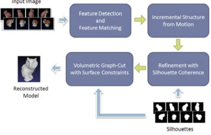
An overview of our approach is illustrated in Fig. 1. Given a set of uncalibrated images and their corresponding silhouettes, we first recover camera motions with an incremental structure from motion (SfM) approach. A further refinement of camera
parameters is achieved by exploiting silhouette co-herence constraints. To reconstruct a 3D model of the target object from calibrated images, we identify a set of surface points from silhouettes, define an occlusion robust measurement of photo-consistency for each surface point, and seek the optimal sur-face by enforcing both photometric and geometric consistency constraints in graph-cut optimization.
B. Problem Formulation
A perspective projection camera model is con-sidered in our system where each camera can be parameterized by a projection matrix with 11 de-grees of freedom. Making the common additional assumptions that the pixels are square, the center of projection is coincident with the image center, known or ideal aspect ratio and the skew factors, and ignoring radial distortion, the number of param-eters can be reduced to 7: three paramparam-eters for the orientation and three parameters for the translation, which together define the camera pose, and one additional parameter for focal length. Without loss of generality, the focal length can be considered constant among all images and the intrinsic matrix is identical when using the same camera during photographing. As a consequence, the camera pro-jection matrix Pi of image Ii can be decomposed
as follows:
Pi = K[Ri|ti] = K[R(ωi)|ti], (1)
where R(ωi) corresponds to the 3D rotation by an
angle θi about a fixed axis specified by the unit
vector ˆni:
R(ωi) = I+sin θi[ˆni]×+(1−cos θi)[ˆni]2×, ωi = θinˆi.
(2) Given a set of N images Ii of a rigid object
and their corresponding silhouettes Si, our goal is
to recover automatically all the projection matrices
P = {Pi} as a set of 6N + 1 parameters Θ =
[f, ωi, ti], and reconstruct the 3D model from the
auto-calibrated images.
C. Features Detection and Feature Matching
The first step is to detect features in each image. We choose SIFT (Scale Invariant Feature Trans-form) [24] feature detectors for its invariance not only to image rotation and translation, but also
to image scale and a substantial range of affine distortion, noises, and changes in illumination.
Since each surface point is observed from mul-tiple images, a single feature may correspond to features in many images. Once features have been extracted from all images, they need to be matched or tracked among images to identify the corre-spondences. We use Mount’s approximate nearest neighbors library [1] to efficiently match features for each image pair in the 128−dimension SIFT feature space, and use RANSAC [11] to robustly estimate a fundamental matrix for the pair to find a set of geometrically consistent matches.
Matching features across images are then col-lected into a connected set, which is called a track as in [31]. Only consistent tracks that contain no more than one feature in one image are kept for camera estimation.
D. Incremental Structure from Motion
After consistent feature tracks among images have been identified, a structure from motion pro-cedure is used to recover camera motions and 3D locations of the corresponding surface points. It can be seen as an optimization problem which attempts to minimize the reprojection errors computed from the recovered parameters, i.e., the sum of distances between the projections of each surface point and its corresponding image positions. Algorithms such as the Levenberg-Marquardt algorithm [27] can be used to solve this non-linear least squares problem. However, this kind of algorithms are usually only guaranteed to find local minima and hence depend on good initialization to find the optimal solution. It is very likely that the large-scale SfM problem will get stuck in some bad local minima if camera motions and 3D positions of surface points were estimated all together right at the beginning. Therefore we adopt an incremental approach, first proposed by Brown and Lowe [3] and refined by Snavely et al. [31], which adds new cameras into the optimization ones at a time. Specifically, the camera parameters of and the tracks observed by the new camera are incorporated into the optimization process.
The SfM procedure begins with a single pair of views which contains the largest number of matches along a large enough baseline. Once the camera
parameters of the initial pair and 3D locations of the observed feature points stabilize, another camera that shares the largest number of feature points is added into the optimization. The intrinsic and ex-trinsic parameters of the new camera are initialized using the direct linear transform (DLT) approach [16] inside a RANSAC procedure.
Tracks observed by at least one of the recov-ered cameras and the new camera at the same time are then added into the optimization, subject to the constraint where their locations estimated using triangulation are well-conditioned. Provided with initial estimates, the sparse bundle adjustment library provided by Leourakis and Argyros [23] is used to simultaneously refine the 3D structure and camera parameters by minimizing the reprojection errors between the observed and projected image locations of feature points at each iteration.
The optimization procedure is repeated until there is no remaining camera that observes any recon-structed 3D points.
E. Refinement with Silhouette Coherence
A further refinement for camera parameters is carried out by exploiting the rigidity property of 3D objects and the concept of silhouette coherence introduced by Hern´andez et al [17]. In brief, given a set of silhouettes Si of a 3D object taken from
different points of view and the corresponding set of camera projection matrices Pi, we would like
to measure how likely the silhouettes could be generated by the real object given those projection matrices. Camera calibration can again be formu-lated as an optimization problem where silhouette coherence is treated as an energy function to be maximized by varying camera parameters.
Since visual hull is constructed as the intersec-tion of visual cones generated by the silhouettes of the scene and the associated camera projec-tion matrices [2], it is very sensitive to errors in forgound/background segmentation and inaccurate camera parameters. If the segmentation and the camera parameters are both perfect, the recon-structed visual hull will be a convex surface that capture the approximate geometry of the real object and contains the object, and its back-projection with respect to the image frame will be exactly the same as the original silhouette. But in practice, either
Fig. 2. Project the reconstructed visual hull back onto image Ii.
The back-projection of visual hull SiVis shown in dark gray and the
original silhouette Si is shown in red.
the silhouettes are noisy or the camera projection matrices are inaccurate, which typically result in a smaller reconstructed visual hull, and the projected silhouettes will be inconsistent with the original silhouettes, e.g., the reconstructed silhouettes are contained in the original ones.
Based on the above observation, we can use the reconstructed visual hull to measure the silhouette coherence as follows:
• Compute the visual hull V by a set of silhou-ettes Si and the corresponding set of camera
projection matrices Pi.
• Project the reconstructed visual hull back onto all images to generate a set of projected silhou-ettes SiV.
• Compare the projected silhouettes SiV with the original ones Si, as shown in Fig. 2.
We define the similarity C between original sil-houette Si and the reprojected silhouette SiV as
C(Si, SiV) = 1− ∫ (Si ∪ SiV)−∫ (Si ∩ SiV) ∫ Si , (3)
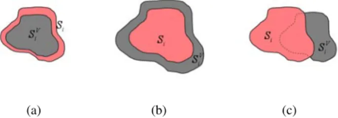
in which we concern not only the area of intersec-tion between two silhouettes but also the area of their subtraction at the same time. That is, we want to maximize the area of intersection with penalty for the part of reconstructed silhouette outside of the original one as shown in Fig. 3.
Unlike Hern´andez et al. who adopt a δ-offset silhouette contour approach to overcome the high computational cost for calculating the integration of silhouette area, we turn to the GPU to obtained silhouettes by rendering the reconstructed visual hull for efficiency. On the other hand, it is very time-consuming if we reconstruct the visual hull when-ever the camera parameters change even slightly
(a) (b) (c)
Fig. 3. Correlation between two silhouettes. The projection of reconstructed visual hull SVi is shown in dark gray and the original
silhouette Si is shown in red. (a) The reconstructed silhouette is
contained in the original silhouette. (b) The reconstructed silhouette contains the original silhouette. (c) Part of the reconstructed silhouette intersect the original silhouette.
and evaluate the silhouette coherence from the dy-namically reconstructed visual hull. For this reason, we reconstruct the visual hull at the beginning of each iteration with cameras projection matrices obtained from the previous iteration, and exploit the silhouette coherence defined as Equation (3) to find the optimal solution of the projection matrix that best fits the current visual hull for each camera independently. Although cameras are not taken into the optimization process as a whole during the same iteration, it is supposed that the overall silhouette coherence will be improved after many iterations as long as each camera has been refined in its turn.
F. Volumetric Graph-Cuts with Surface Constraints
To reconstruct 3D models from calibrated images, we first introduce the measure of photo-consistency for each scene point, and give a description of the graph structure we used to apply the graph-cut algorithm. Finally, we show how to impose silhouette constraints into the optimization.
Given a sequence of N calibrated images, the photo-consistency of a 3D point x in space can be evaluated by projecting the point back to all images where it is visible and computing the normalized cross-correlation(NCC) among them. To discard the visibility computation, a voting technique similar to the one proposed in [35] is used. The basic idea is to treat all potential causes of mismatches such as occlusion, image noise, lack of texture, shadows or highlights as outliers in the matching process. More specifically, we define the photo-consistency value
Fig. 4. Project a potential scene point x back into the selected reference image Ii and its neighbor Ij; compute the NCC score
between the projected patches.
ρ(x) for the given point x as ρ(x) = exp { −µ∑N i=1 VOTEi(x) } , (4)
where µ represents the rate of decay and is related to the distribution of votes among all scene points. The photo-consistency function ρ(x) is the same as in [35], but the value of VOTEi(x) is computed
in a slightly different way:
• Project the 3D point x onto a reference image
Ii and its k nearest imagesN (i) whose camera
poses cj∈N (i) are closest to ci.
• Compute the k correlation scores between im-age Ij∈N (i) and the reference image Ii. The
score is evaluated using normalized cross-correlation (NCC) between two nc × nc
win-dows centered on the projections of x on each of the views Ii and Ij∈N (i), as shown in Fig. 4. • The score defines the correlation between two projected patches and the 3D location x gets a vote if the score is higher than a threshold ε as follows:
VOTEi(x) =
∑
j∈N (i)
Cij(x), (5)
where Cij(x) is a binary function that stands
for the agreement of photometric consistency between the projections of x on Ii and Ij:
Cij(x) =
{
1, if N CC(ˆxi, ˆxj)≥ ε
0, otherwise . (6)
From the definition in Equation (5), the maxi-mum votes VOTEi(x) that a scene point x can
get is k. Dividing the summation of VOTEi(x) in
Equation (4) by N × k we can map the function
values to the nonnegative interval [0, 1] and obtain a normalized function.
As mentioned in [35], the graph-cut algorithm usually prefers shorter cuts, which may result in cutting off the protrusive parts of the object surface, hence an inflationary (ballooning) term is added to alleviate such flatten phenomenon. Intuitively, one can imagine that there exists a force from inside of the object that tries to inflate or distend the object like blowing up a balloon. The graph-cut algorithm is then used to find the optimal object surface which minimizes a surface integral of photo-consistency and maximizes volume at the same time.
To adopt the graph-cut algorithm for volumetric stereo, a graph structure is constructed by first quantized the 3D space into voxels of size h×h×h and creating a graph node for each voxel. Each node is connected to its 6-neighbors by edges with weight
wij =
4πh2
3 ρ(
xi+ xj
2 ), (7)
where xi and xj are centers of two neighboring
voxels, and ρ(x) is the matching cost function defined in Equation (4);
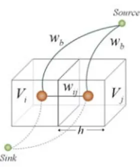
Besides the weighted edges joining two neighbor-ing nodes in the graph, each node is also connected to the Source node and the Sink node which represent ”object” and ”empty space” respectively. For voxels that are sure to be outside of the object, the weight of the edge connecting the corresponding nodes to the Sink node are set to inf inity in order to ensure that they remain outside of the reconstructed shape. For the remaining voxels, the weights of the edges connecting the nodes to the
Source node are set to wb = λh3, which stands for
the ballooning force that encourage the object that fill in the bounding volume. The configuration of the graph is shown in Fig. 5.
However, the photo-consistency measure alone are not always sufficient to preserve protrusions and pursue concavities on the object surface at the same time since it depends on the characteristic of the object and the quality of input images. The powerful silhouette cue is again incorporated into the optimization process as a shape prior to recover more accurate geometry.
Let x be a 3D point which is believed to lie on the true surface of the object but is outside of the
Fig. 5. The correspondence of voxels with nodes in the graph. Each voxel is connected to its neighbors as well as the Source and Sink nodes.
reconstructed surface, i.e., x can be seen as a surface constraint point which stands for a protrusive part of the object surface and has been cut off by graph-cut. Given a set of surface constraint points X, our goal is to construct the actual surface S∗ that passes through every point x ∈ X.
Because it is difficult to apply such constraints directly on the 3D graph-cut algorithm due to the local influence of a single graph node with respect to the whole graph, we adopt an indirect approach, inspired by [32], that tries to block the surface from cutting a continuous region connecting x and the base surface Sbase, obtained from the graph-cut
algorithm which considers photometric consistency along, that captures fine details on the object surface while parts of protrusions being cut off.
Denote the apparent contour of silhouette Si by
γi. For each candidate pixel on γi, we first compute
the corresponding optic ray oi(d) that goes through
the camera’s optic center ci and the 3D location xs
of the candidate pixel on the image plane by the following equation:
oi(d) = xs+ (ci− xs)d. (8)
Based on the concept of silhouette coherence, each optic ray oi(d) must touch the object surface
at some point x, and all rays from the associated camera center ci graze the object along a surface
curve called the rim Γi [30]. As a result, we search
along the optic ray for the point x that is closest to the object surface and assume it is a true surface point on the rim Γi. More precisely, we search on
the object surface to find a point p that is closest to the optic ray and back project it onto the ray to get the projection point x as shown in Fig. 6(a). Since
(a) (b)
Fig. 6. Surface constraints derived from silhouette. (a) Back project the point p on the object surface that closest to optical ray oi(d)
to get the surface constrained point x. (b) All points on the path connecting the constraint point x and the closest surface point p are collected to the set BL(x) as the blocking regions shown in blue. The base surface is shown as the black curve whereas the red one represents the true surface.
x is supposed to lie on the object surface and p is
the closet point on the surface, all points on the path connecting x and p are collected into a set BL(x) (called a blocking region as in [32]) as shown in Fig. 6(b).
Then we incorporate the geometric constraints into the graph-cut optimization by setting the weight of the edge joining the corresponding graph node of each point in BL(x) and the Sink node to ws =
4π 3 h
2, where h is the voxel size. By the definition
of wij in Equation (7), this is the maximum weight
for edges between any two neighboring voxels and it constrains the solution cut to not pass through all blocking regions derived from silhouettes. Even-tually, the protrusion parts that have been cut out originally may retain on the improved reconstructed surface.
IV. Experiments and Results
In this section, we present some experimental results of camera calibration and 3D reconstruction. We evaluated our approach with 2 real data sets: the toy owl and the toy house. The owl sequence con-tains 96 images, and the house sequence concon-tains 120 images.
We use the silhouette coherence defined in Equa-tion (3) to evaluate the accuracy of our automatic calibration results. To be more intuitive, the ratio of area between the original silhouette and the silhouette obtained from projection of reconstructed
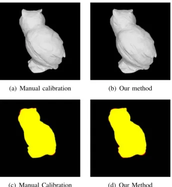
(a) Manual calibration (b) Our method
(c) Manual Calibration (d) Our Method
Fig. 7. Reconstructed visual hulls of the owl for a selected view and the corresponding silhouette coherence . Left: model reconstructed from manual calibrated images. Right: model reconstructed from self-calibrated images using our method.
TABLE I
SILHOUETTE COHERENCE FOR A SELECTED VIEW–OWL Intersection % Coherence Manual Calibration 99.0306% 0.986279 Our Method 98.5969% 0.983877
visual hull, defined as:
C(Si, SiV) = ∫ (Si ∩ SiV) ∫ Si ∈ [0, 1], (9)
is also used to compare the similarity between the two silhouettes, where higher percentage of intersection implies that the reprojected silhouette is closer to the original one in the case that visual hull is contained in the real object, and thus the calibration result is considered to be more accurate. We compare the results of manual calibration and our method with the two measurements mentioned above. The manual calibration is performed by the technique proposed by Zhang [37], which is proved to provide very good results and is widely used for camera calibration. We reconstruct visual hulls for the toy owl using camera parameters obtained from both our calibrated method and manual calibration. Fig. 7 shows back views of the reconstructed model
TABLE II
AVERAGE SILHOUETTE COHERENCE–OWL Avg. Intersection % Avg. Coherence Manual Calibration 99.3808% 0.988559 Our Method 98.0271% 0.978078
and the correlation between the original silhouettes and the projected silhouettes. The original silhouette is drawn in red, the projected silhouette of the reconstructed visual hull is drawn in green, and so the intersected area is shown in yellow.
The evaluation of accuracy is listed in TABLE I, where the values of Intersection % and Coherence are computed from Equation (3) and Equation (9) respectively. The average scores computed from all images are listed in TABLE II.
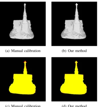
For the toy house, a view is selected to render the reconstructed visual hull as shown in Fig. 8, and the correlation between the original silhouettes and the projected silhouettes are also depicted. It is clear that the calibration result obtained from our method is close to that by manual calibration. The tower of the reconstructed house is sharpened due to the inaccurate camera calibration, but this phenomenon is less obvious in the visual hull reconstructed with camera parameters calibrated automatically by our method as shown in TABLE III. TABLE IV gives average scores computed from all images.
We compute NCC between projected patches from a 7× 7 window, and the spatial resolution of voxel grids was set to 3503 voxels in our experi-ments. Higher spatial resolution results in models with higher quality but also takes more time to reconstruct the model. Fig. 9 and Fig. 10 shown the results of model reconstruction from the owl and the house image sequences respectively. Some of the input images are shown in the leftmost column, and the middle column are similar viewpoints of models reconstructed via volumetric graph-cut with photo-consistency constraints alone. Images in the rightmost column shown the models reconstructed by our method, where both photometric and geo-metric constraints are taken into consideration.
Since the geometry of the toy owl is quite sim-ple without many protrusions on the surface, the contribution of exploiting silhouette constraints is not evident. However, if we take a close look at
(a) Manual calibration (b) Our method
(c) Manual calibration (d) Our method
Fig. 8. Reconstructed visual hulls of the house for a selected view and the corresponding silhouette coherence . Left: model recon-structed from manual calibrated images. Right: model reconrecon-structed from self-calibrated images using our method.
TABLE III
SILHOUETTE COHERENCE FOR A SELECTED VIEW–HOUSE Intersection % Coherence Manual Calibration 98.8449% 0.984335 Our Method 99.0694% 0.984592
the model, we can see that some dents due to the over-carving of graph-cut when considering along the photometric constraints have been filled up. In case of the toy house, it is obvious to observe that the cross on the top of the tower is as thick as how it is in the original images as shown in Fig. 10, and the thinned parts of the tower and the cross have been fatten by our method because of the geometric constraints.
TABLE IV
AVERAGE SILHOUETTE COHERENCE–HOUSE Avg. Intersection % Avg. Coherence Manual Calibration 98.9923% 0.986454 Our Method 98.8193% 0.984933
V. Conclusions
In this work, we present an approach to recon-struct 3D models from uncalibrated images. We adopt the assumption that silhouettes are available and exploit advantages of both point-based and silhouette-based methods in our automatic cam-era calibration procedure. An incremental structure from motion method is first applied to recover cam-era parameters using corresponding features among images. Then we utilize the concept of silhouette coherence, which defines the similarity between the input silhouettes and the projected silhouettes of the reconstructed visual hull, to refine the camera parameters.
After we have obtained a set of self-calibrated im-ages, a shape-independent photo-consistency met-ric is used to extract the minimal surface via a volumetric graph-cut algorithm. Our measure of photo-consistency works by projecting each poten-tial scene point into the input images, and evaluating the amount of mutual agreement between those pro-jections by normalized cross-correlation. A voting scheme is used to avoid computing visibility for every point on the object surface. The silhouette cue is again incorporated into the optimization process as a shape prior along with the photo-consistency measure to recover precise geometry. We propose a simple method to identify a set of points that lie on the object surface from silhouettes and constrain the reconstructed surface to pass through or close to these points.
We validate the proposed method on 2 real data sets that both contain over 90 images. The results of camera calibration are quite accurate and are comparable to those obtained by manual calibration. The models reconstructed by enforcing both photo-metric and geophoto-metric consistency constraints exhibit surface details as well as the protrusive parts in the meantime.
One of the limitations of the proposed approach is that it cannot recover concavities that are too deep to be carved away by the graph-cut. To exploit the silhouette constraints for both camera calibra-tion and model reconstruccalibra-tion, the requirement of foreground/background segmentation for each input image also limits the feasibility of the current ap-proach since silhouettes are not always available. As
Fig. 9. Toy owl. Left column: image sequence. Middle column: similar viewpoints of the model reconstructed via volumetric graph cut with photo-consistency constraints alone. Right column: similar viewpoints of the model reconstructed via volumetric graph cut with both photo-consistency and silhouette constraints.
a consequence, a 2D segmentation algorithm can be incorporated into our camera calibration and model reconstruction framework to extract silhouettes from input images automatically, which makes the system of multi-view stereo reconstruction fully automatic and more practical.
VI. Acknowledgment
This work was supported in part by Excellent Research Projects of National Taiwan University under grant 98R0062-04.
REFERENCES
[1] S. Arya, D. M. Mount, N. S. Netanyahu, R. Silverman, and A. Y. Wu. An optimal algorithm for approximate nearest neighbor searching in fixed dimensions. Journal of the ACM, 45(6):891–923, 1998.
[2] B. G. Baumgart. Geometric Modeling for Computer Vision. PhD thesis, Stanford University, 1974.
[3] M. Brown and D. G. Lowe. Unsupervised 3D object recog-nition and reconstruction in unordered datasets. In 3DIM ’05: Proceeding of the 5th International Conference on 3D Digital Imaging and Modeling, pages 56–63, 2005.
Fig. 10. Toy house. Left column: image sequence. Middle column: similar viewpoints of the model reconstructed via volumetric graph cut with photo-consistency constraints alone. Right column: similar viewpoints of the model reconstructed via volumetric graph cut with both photo-consistency and silhouette constraints.
[4] N. Campbell, G. Vogiatzis, C. Hernandez, and R. Cipolla. Automatic 3D object segmentation in multiple views using volumetric graph-cuts. Image and Vision Computing, 2008. [5] L.-W. Chan, Y.-F. Chuang, M.-C. Yu, Y.-L. Chao, M.-S. Lee,
Y.-P. Hung, and J. Hsu. Gesture-based interaction for a magic crystal ball. In VRST ’07: Proceedings of the ACM Symposium on Virtual Reality Software and Technology, pages 157–164, 2007.
[6] C.-W. Chen, L.-W. Chan, Y.-P. Tsai, and Y.-P. Hung. Aug-mented stereo panoramas. In ACCV ’06: Proceedings of the 7th Asian Conference on Computer Vision, pages 41–49, 2006. [7] S. E. Chen. QuickTime VR - an image-based approach to virtual
environment navigation, 1995.
[8] Y.-J. Chen, C.-F. Chang, and Y.-P. Hung. High quality novel view generation of object movies. In CVGIP ’08: Proceedings of 21th IPPR Conference on Computer Vision Graphics and Image Processing, 2008.
[9] R. Cipolla and K. E. A. smf Peter J. Giblin. Motion from the frontier of curved surfaces. In ICCV ’95: Proceedings of the 5th International Conference on Computer Vision, page 269, 1995.
[10] B. Curless and M. Levoy. A volumetric method for building complex models from range images. In SIGGRAPH ’96: Pro-ceedings of the 23rd annual conference on Computer graphics
and interactive techniques, pages 303–312, 1996.
[11] M. A. Fischler and R. C. Bolles. Random sample consensus: A paradigm for model fitting with applications to image analysis and automated cartography. Communications of the ACM, pages 726–740, 1981.
[12] J.-S. Franco, , J. se’bastien Franco, and E. Boyer. Exact poly-hedral visual hulls. In In British Machine Vision Conference, pages 329–338, 2003.
[13] Y. Furukawa and J. Ponce. Carved visual hulls for image-based modeling. International Journal of Computer Vision, 81(1):53– 67, 2009.
[14] M. Goesele, B. Curless, and S. M. Seitz. Multi-view stereo revisited. In CVPR ’06: Proceedings of the 2006 IEEE Computer Society Conference on Computer Vision and Pattern Recognition, volume 2, pages 2402–2409, 2006.
[15] M. Goesele, N. Snavely, B. Curless, H. Hoppe, and S. M. Seitz. Multi-view stereo for community photo collections. In ICCV ’07: Proceedings of the 11th IEEE International Conference on Computer Vision, pages 265–270, 2007.
[16] R. Hartley and A. Zisserman. Multiple View Geometry in Computer Vision. Cambridge University Press, 2004.
[17] C. Hernandez, F. Schmitt, and R. Cipolla. Silhouette coherence for camera calibration under circular motion. IEEE Transac-tions on Pattern Analysis and Machine Intelligence, 29(2):343– 349, 2007.
[18] Y.-P. Hung, C.-S. Chen, Y.-P. Tsai, and S.-W. Lin. Augmenting panoramas with object movies by generating novel views with disparity-based view morphing. Journal of Visualization and Computer Animation, 13(4):237–247, 2002.
[19] M. Kazhdan, M. Bolitho, and H. Hoppe. Poisson surface re-construction. In SGP ’06: Proceedings of the 4th Eurographics Symposium on Geometry Processing, pages 61–70, 2006. [20] C.-H. Ko, Y.-P. Tsai, Z.-C. Shih, and Y.-P. Hung. A new
image segmentation method for removing background of object movies by learning shape priors. In ICPR ’06: Proceedings of the 18th International Conference on Pattern Recognition, pages 323–326, 2006.
[21] A. Laurentini. The visual hull concept for silhouette-based image understanding. IEEE Transactions on Pattern Analysis and Machine Intelligence, 16(2):150–162, 1994.
[22] S. Lazebnik, E. Boyer, and J. Ponce. On computing exact visual hulls of solids bounded by smooth surfaces. In CVPR ’01: Proceedings of the 2001 IEEE Computer Society Conference on Computer Vision and Pattern Recognition, pages 156–161, 2001.
[23] M. I. A. Leourakis and A. A. Argyros. The design and implementation of a generic sparse bundle adjustment software package based on the Levenberg-Marquardt algorithm. Techni-cal Report 340, Institute of Computer Science - FORTH, 2004. [24] D. G. Lowe. Distinctive image features from scale-invariant keypoints. International Journal of Computer Vision, 60(2): 91–110, 2004.
[25] W. Matusik, C. Buehler, R. Raskar, S. J. Gortler, and L. McMil-lan. Image-based visual hulls. In SIGGRAPH ’00: Proceedings of the 27th annual conference on Computer graphics and interactive techniques, pages 369–374, 2000.
[26] W. Matusik, C. Buehler, L. McMillan, and S. Gortler. An efficient visual hull computation algorithm, 2002.
[27] J. Nocedal and S. J. Wright. Numerical Optimization. Springer, 1999.
[28] J. Porrill and S. Pollard. Curve matching and stereo calibration. Image and Vision Computing, 9(1):45–50, 1991.
[29] S. M. Seitz, B. Curless, J. Diebel, D. Scharstein, and R. Szeliski. A comparison and evaluation of multi-view stereo reconstruc-tion algorithms. In CVPR ’06: Proceedings of the 2006 IEEE Computer Society Conference on Computer Vision and Pattern Recognition, volume 1, pages 519–528, 2006.
[30] S. N. Sinha and M. Pollefeys. Multi-view reconstruction using photo-consistency and exact silhouette constraints: A maximum-flow formulation. In ICCV ’05: Proceedings of the 10th IEEE International Workshop on Vision Algorithms, pages 349–356, 2005.
[31] N. Snavely, S. M. Seitz, and R. Szeliski. Photo tourism: Explor-ing photo collections in 3D. In SIGGRAPH ’06: ProceedExplor-ings of the 33rd International Conference on Computer Graphics and Interactive Techniques, pages 835–846, 2006.
[32] S. Tran and L. Davis. 3D surface reconstruction using graph cuts with surface constraints. In ECCV ’06: Proceedings of the 9th European Conference on Computer Vision, pages 219–231, 2006.
[33] B. Triggs, P. McLauchlan, R. Hartley, and A. Fitzgibbon. Bun-dle adjustment - a modern synthesis. In ICCV ’99: Proceedings of the 7th IEEE International Workshop on Vision Algorithms, pages 298–372, 2000.
[34] G. Vogiatzis, P. H. S. Torr, and R. Cipolla. Multi-view stereo via volumetric graph-cuts. In CVPR ’05: Proceedings of the 2005 IEEE Computer Society Conference on Computer Vision and Pattern Recognition, volume 1, pages 391–398, 2005. [35] G. Vogiatzis, C. H. Esteban, P. H. S. Torr, and R. Cipolla.
Multiview stereo via volumetric graph-cuts and occlusion robust photo-consistency. IEEE Transactions on Pattern Analysis and Machine Intelligence, 29(12):2241–2246, 2007.
[36] X.-T. Wu, Y.-P. Hung, and C.-L. Yang. 3D object reconstruction from multi-view images. Master’s thesis, Department of Com-puter Science and Information Engineering, National Taiwan University, Taiwan, 2007.
[37] Z. Zhang. A flexible new technique for camera calibration. IEEE Transactions on Pattern Analysis and Machine Intelli-gence, 22:1330–1334, 1998.