Analysis and Design of EM1 Filter for Multi-Output
Switching Mode Power Supply
Zong-Yu He*, Fu-Yuan Shih*, Yie-Tone Chen** and Yan-Pei Wu*
*
Department of Electrical Engineering National Taiwan UniversityTaipei, Taiwan, R.O.C.
** Department of Electrical Engineering National Yun-Lin Institute of Technology Tou-Liu City, Yun-Lin County, Taiwan, R.O.C.
Abstract
In this paper, a generalized method has been used to discuss the lnfluence of the E M filter on the stability and the performance of multi-output switchng mode power supplies. A criteria for the design of single
stage EMI filter has been proposed. This criteria will
satisfy the requirement of specification in EMI and will guarantee the system to be stable at the same time. Furthermore, whether there exists the post regulator or preregulator in the system or a single output system, the generalized formula of performance derived in this paper will work as well.
I. Introduction
Electromagnetic Interference(EM1) has become the major problem for the designers and manufactures of switching mode power supply in recent years. Because the EMI noise caused by the discontinuous switching current ripple of a switching power supply is always over the noise immunity of the other equipments, it has become the most important part in the design of switchmg power supply to reduce such kind of high frequency noise and make tlie product to
meet the ,requirement of E M specification. To
overcome this problem, a lowpass filter, so-called EM1 filter or input filter, is usually added in front of the switching power stage. However, when the EM1 filter was utilized, it lead to the degradation effect of the characteristics of switching power supply, even cause the instability of the overall system. The situation will become more serious when the designers apply tlie topology of multi-output power supplies. The reason is that the multi-output scheme is often used to design hgher power and meets more other requirements. If the multi-output power supplies consist of post- regulators, the problem will become more complicated. In this paper, the affection of EM1 filter to the stability and performance of the multi-output forward
power converters will be discussed. The reason of instability will be presented and the design criteria of EM1 filter will be also discussed. After the criteria have been met, the designers can make their products meet the requirement of safety and guarantee tlie stable operation. Furthermore, the generalized formulas of performance will be derived, so whether there exist the
post regulators in the system or for a single-output
system, the formulas will work as well. Then, the results of simulation and experiment will be presented.
Section V concludes the paper.
11.
Small-Signal Model of Two-Output
Forward Converters
Figure 1 shows the circuit diagram of a two-output forward converter. The main output is regulated tluough the duty ratio control of the switch
S1 and the auxiliary output is regulated by the post
regulator. The detail of the control transfer function of Fig. 1 will be derived below.
According to the different conduction state of
main switch S1 and tlie switch S2 of post
regulator(Fig.2), the two-output converter will have the following three different conduction periods: (1) Switch1 is in conduction and switch 2 is opened (2)
Switch 1 and switch 2 are both in conduction ( 3 )
Switch 1 and switch 2 are both opened. Fig. 3 shows
the equivalent circuit diagram of the above t h e e different conduction periods. By the principle of state-space avering[ 11, the control transfer function of Fig. 1 can be derived and is summarized in Table I. From the results of Table I, if one makes D2=0 and T2=0, the situation will like that without a post regulator. On the contrary, if one makes D2=D1, then the situation will like that of single output. Thus Table I is also applied to two-output forward converters without post regulator and the single-output forward
/Jy
I
1/vp 1
L
Y r IFigure 1 The circuit diagram of a two-output forward converter with post-regulator
".*
1
(c)
Figure 2 The three different states of a period (a)swl-on, sw2-off (b)swl-on, sw2-on (c)swl-off, sw2-off
Table I Transfer Functions of Two-Output Forward Converters with Post Regulator
V O l A 1 s 1
- t 2 2 = -(-)(-j Ct A I TI
i.
converters. The input admittance
t
in Table I will benegative when T1 and T2 are much larger than one.
Because of the characteristic of the negative
impedance, when the input filter is added to the system additionally, the system will have the potential of
unstable. About the problem of stability, section I11
will discuss it briefly.
In ideal case, the load variation of output #2 will have no affection on the output voltage of output #1, but the load variation of output #1 does have the
affection for the output voltage of output #2. The
results can be obtained from
?
and?
in Table I.From the expression of
?,
if T1 can be made to equalthen the output #2 will not be influenced by to
-
0 1 - 0 2 'the input interference in theory, but in practice, T1 cannot be kept to be constant.
V i
it2 i,l
V i 0 2
111. The Switching Power Supply with EM1
Filter
( 1)Audiosusceptibility Consideration
EMI filter used in switchmg power supply(SPS)
is shown in Figure 3. From the theorem of reciprocity,
one can obtain
,.
h
Because the requirement of EMI filter is often a
low-pass filter, so Z2(s) is mainly composed of
resistive and capacitive elements, and Zl(s) is composed of resistive and inductive elements in
practice. Figure 3 can then be equivalent to Figure 4 by
the Thevenin theorem. From Figure 4 and Table I, the
variation of input voltage-to-output voltage for the
two-output forward converters with EMI filter can be
derived and is summarized in the following.
- s + 1 IC 1 V n =
D l n l ( ~ ] ( & - ) H s ( s ) *
A
vo+ I
2 - IFigure 3 EM1 filter and two-output linearized switching regulator V n C S ) Z i
( S )
= V n " C S > s H s C S > - - - zs c s >=z 1 c s > / / z 2 c s > Z i C S > = T h e i m p e d a n c e o f o r i g i n a l p o u e r s u p p l y h h V n ' C S > = T h e T h e v e n l n ' s v o l t a p e o f V n " C 5 )Figure 4 EM1 filter and equivalent input impedance of SPS
Let
Assume that Zs(s)<<Zi(s), then (2) and (3) can be approximated to be
?
=Gvl (s)HS(s)/(
1
+
T i )
V n
Where Gvl(s) and Gv2(s) are the
uncompensated audiosusceptibility of output # 1 and
output #2.
(2) Stability Consideration
When a EMI filter is added to a SPS, the
performance of the origmal system may be changed.
The characteristic equation of the new system can be proved to be
(l+Zs(s)/Zi(s))(l+Tl)(l+T2) = 0 (8)
One can conclude fiom the above equation that
the adding of EMI filter is like to increase a new
feedback loop, and the open loop gain is Zs(s)/Zi(s). Assume that the original system is stable, then (1 +T 1 )( 1 +T2) will have no right half plane(RHP) roots. Because of the reason, if the following equation
has no RHP roots, then the new system with E M filter
can be stable.
l+Zs(s)/Zi(s) = 0 (9)
Apparently, as long as
I
zs(S)I
<<
I
Z i ( S )I,
the new system will have not the problem of stability.
The conclusion is like that of single output[2]. Before
continuing to consider the stability problem, what kind of the input filter belongs to must be determined fist. In this paper, a single-stage LC filteflshown in Figure
5 ) is applied. The attenuation function Hs(s) of this
single-stage filter is
and the equivalent impedance Zs(s) of this single-stage
filter is
The resonant frequency of this filter is
wp
=-
, and its zero isw Z
=rcFf
.If the attenuation of a system is required to be
A(-2010gA
a),
the restriction of the elements of theh h
~
~ ~ ; .
V O C S )-
-
&
-
Figure 5 Single-stage lowpass LC filter
filter can be achieved according to the relative location of Wn, Wp, and Wz. (a) Wn>>Wz (b)Wz>>Wn>>Wp If
Cf
<<
*
(14) (15) A thenLf>
7 Wn C,The above restriction can be used to dktermine the value of component at the begining of the filter design.
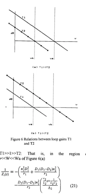
M e r the decision of the kind of the filter has been made, the stability will then be discussed according to the different magnitude of loop gains T1 and T2. The discussion can be classified into the
following three cases :
(a)T1, T2 >> 1: That is, in the region of W<<Wb of Figure 6(a) or in the region of W<<Wa of Figure 6(b)
- P
- --
V iWhere P is the output power of the original
power supply, Vn is the steady-state input voltage, and
Vi is the extemal input DC source.
Substitution of equations (17), (16), and (1 1)
into equation (9), and according to the rule of
Routh-Hurwitz, the another constraints can be obtained to be
ubi ua:
( a ) T l > > T P
u a : u b i
Cb) T l < < T 2
Figure 6 Relations between loop gains T1 and T2
(b)Tl>>l>>T2: That is, in the region of
Wb<<W<<Wa of Figure 6(a)
If D2 is set to zero, the input admittance of a two-output forward converter without the post regulator can be achieved.
(c)T2>>1>>Tl: That is, in the region of
Wb>>W>>Wa of Figure 6(b)
For cases (b) and (c), the accurate prediction of the constrained value of rd is difficult. The practical design rule is: (1) avoid the resonant frequency of EMI filter to approach the resonant frequencies of output #1 and output #2 (2) check if
(3) Performance Degradation Consideration
After the adding of input EM1 filter, the performance of the overall system will be degraded. What affection of performance degradation by the EM1 filter can be estimated from Table 11. In section IV, the practical simulation and experimental examples can be demonstrated.
Table I1 Performances of Two-Output Forward Converters with EM1 Filter
IV. Simulation and Experimental Results The following specification of the two-ouput forward converter with the post regulator is used to simulate various performance of the coiiverter by the Pspice[3,4].
L1=45uH, C 1=1000~1F, L2=90uH, C2=1 OOOUF,
Fs=80kHz, Vi=48V, P=96W.
To meet the requirement of VDE-087 1A3, the
attenuation will be 63dB at least at the frequency of 80
kHz. According to the criteria of Equations (12), (13), (14), (15), (18), (19), and (20), the single stage EM1 filter can be chosen, they are
Lf=420uH, Cf400uF
The value of rd can be chosen between 0.05Q and 5.7Q. For the reason that the effect of adding a EMI filter can be easily seen fiom the simulation, the value of rd=O.lQ is chosen. After these values have been chosen, the single-stage filter is completely designed. To satisfy the requirement of stability, the conventional compensation method is applied to design
a stable output #1 and output #2. After the EM1 filter
has been chosen and the compensation has been designed, whether the overall system is stable or not must be also checked. From Figure 7, the magnitude of Zs(s) is smaller than Zi(s), so the overall system can be said to be stable.
Figures 8 to 16 show the simulation results for
forward converter with EMI filter. From the simulation results, the effect of adding a EMI filter will degrade
the performance of SPS can be seen, and the
simulation results agree with the calculations fiom
Table 11. Figures 8 to 16 also show the amount of
degradation is greatly affected by the Q factor of the EMI filter. Comparison of Figures 17, 18, and 14 shows the results of experiment and simulation are in agreement.
V. Conclusions
Generalized formula of Two-output forward converters with post regulator have been derived, and the performance degradation of adding a E M filter to the two-output converters has also been analyzed and discussed. The stability criteria of the converters with E M filter has been proposed, too. With these guidelines, the stable and high-performance multi- output converters can be achieved.
References
[ l ] R. D. Middlebrook and S. Cuk', "A general unified approach to modeling switching converter power stages," in Proc. IEEE Power Electronics Specialists C o d , 1976.
[2] R. D. Middlebrook, Input filter considerations in
design and application of switching regulators," IEEE
Industry Applications Society Annual Meeting, 1976 Record.
[3] V. Bello, "Computer aided analysis of switching regulators using SPICE," in IEEE PESC Rec., 1980.
[4] V. Vorperian, "Simplified analysis of
P W M
converters using the model of the PWM switch:Parts I and 11," IEEE Trans. Aerosp. Electron. Syst., Mar. 1990.
80 . . .
-TI; ' " " " " IO' ' " " " ' IO' I ir
Hr
Figure 7 Magnitude of Zi and Zs
-o ...
*
\
With M I filter
-100 ;
\
Audio Susceptibility of Vol.
-150 ...,... l0Kh 100- 1.0h 10h lOOh 1.0-
Frequency
-
.Vdbll41Figure 8 Audiosusceptibility of output #I
0 ... ..., AYdio &sseptibility or V O Z . -200 +. ...,...,...
.
1OKh lOOKh 1.0h 10h 100h 1.oKh Frequency D .vdbl24)Figure 9 Audiosusceptibility of output #2
" 1
1 With EN1 f i l t e r .
1 With EN1 f i l t e r . -40 <
Output Impedance of I ' s t Output.
-Bo+ ...,...,...,
I .Oh
-
IOh lOOh I .Olh IOlih lOOYh. "dJil41
Frequency
Figure 10 Output impedance of output #1
OT... ...
With EM[ filter. 1
I .Oh I Oh lOOh I .OKh lOYh IOOKh
. vm(24)
Frequency
o T ... 101
-\
open Loop g a i n " T 2 "
Cross-Regulation of I'st
-
2 ' n d .-8o+
I .Oh IOh lOOh I .OKh lOKh lOOhh
n v&l241
Frequency
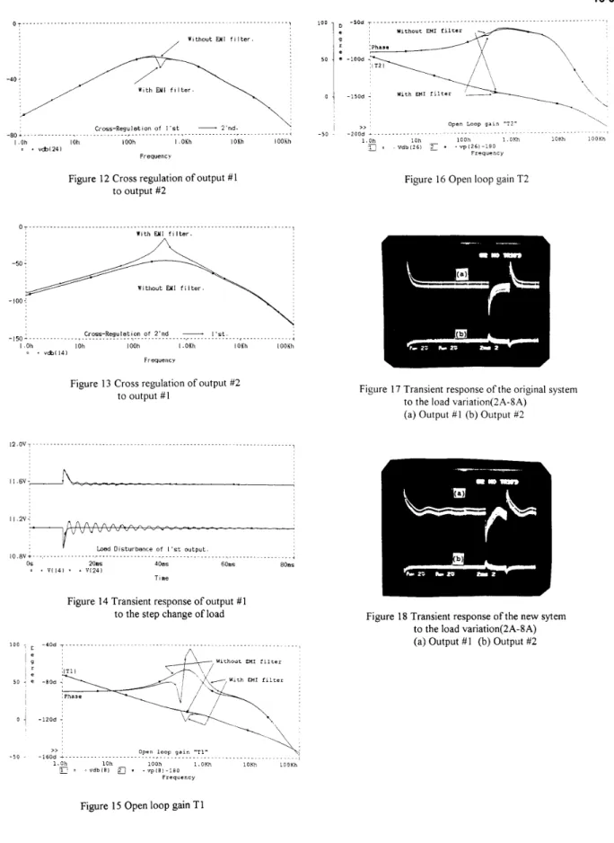
Figure 12 Cross regulation of output #1 to output #2
Figure 16 Open loop gain T2
o. ...
With U11 filter.
Cross-Regulation of 2'nd
-
I'st..150-... ....,...,...,
1 Oh IOh lOOh I .OKh lOKh IOOKh
0 . "Cbl141
Frequency
Figure 13 Cross regulation of output #2
to output # I Figure 17 Transient response of the original system
to the load variation(2A-SA) (a) Output # I (b) Output #2
~ Iy Load Disturbance o f I'st output.
,0.8"+.. ...,...,
OS 20ms 40ms 60ms 80ms
Time
0 * VI141 * 1 Vl241
Figure 14 Transient response of output # I
to the step change of load Figure 18 Transient response ofthe new sytem
to the load variation(2A-8A) (a) Output #I (b) Output 82
$T,
Withoot EH1 filterSI,-,
With EH1 f i l t e r- 8 O d
-120d
-160d >> ... O p e n loop g a i n "TI"
\:
...,1. OKh lOKh lOOKh 1.0h l O h lOOh
r ~ Y d b I B i
a
* . v p I 8 ) - l a O f r e q v e n c y- 5 0 -