A High-Performance and Memory-Efficient Pipeline
Architecture for the 5/3 and 9/7 Discrete
Wavelet Transform of JPEG2000 Codec
Bing-Fei Wu, Senior Member, IEEE, and Chung-Fu Lin, Student Member, IEEE
Abstract—In this paper, we propose a high-performance and memory-efficient pipeline architecture which performs the one-level two-dimensional (2-D) discrete wavelet transform (DWT) in the 5/3 and 9/7 filters. In general, the internal memory size of 2-D architecture highly depends on the pipeline registers of one-dimensional (1-D) DWT. Based on the lifting-based DWT algorithm, the primitive data path is modified and an efficient pipeline architecture is derived to shorten the data path. Ac-cordingly, under the same arithmetic resources, the 1-D DWT pipeline architecture can operate at a higher processing speed (up to 200 MHz in 0.25- m technology) than other pipelined architectures with direct implementation.
The proposed 2-D DWT architecture is composed of two 1-D processors (column and row processors). Based on the modified algorithm, the row processor can partially execute each row-wise transform with only two column-processed data. Thus, the pipeline registers of 1-D architecture do not fully turn into the internal memory of 2-D DWT. For an image, only3 5 internal memory is required for the 5/3 filter, and5 5 is required for the 9/7 filter to perform the one-level 2-D DWT decomposition with the critical path of one multiplier delay (i.e., and indicate the height and width of an image). The pipeline data path is regular and practicable. Finally, the proposed architecture implements the 5/3 and 9/7 filters by cascading the three key components.
Index Terms—JPEG 2000, lifting-based discrete wavelet trans-form (DWT), two-dimensional (2-D) DWT.
I. INTRODUCTION
T
HE TWO-dimensional (2-D) discrete wavelet transform (DWT) has been applied in many image compression tech-niques. The wavelet transform can decompose the signals into different sub-bands with both time and frequency information and supports various methods for analyzing signals. These ad-vantages make DWT widely used in many areas [2]–[4], such as image analysis, digital signal processing and communication. The main issues for hardware implementation are the strong demand for real-time performance and heavy internal memory requirements.The 2-D DWT can generally be realized by two approaches— separable and nonseparable. In this study, we focus on the sep-arable approach, which splits the 2-D DWT implementation
Manuscript received January 19, 2004; revised May 11, 2004. This work was supported by the Ministry of Education of Taiwan, R.O.C., for Promoting the Academic Excellence of Universities, under Contract EX-91-E-FA06-4-4. This paper was recommended by Associate Editor K.-H. Tzou.
The authors are with the Department of Electrical and Control Engineering, National Chiao Tung University, Hsinchu, Taiwan 30050, R.O.C. (e-mail: [email protected]; [email protected]).
Digital Object Identifier 10.1109/TCSVT.2005.858610
into two one-dimensional (1-D) operations (column-wise and row-wise filtering). Although the 1-D column processor can be directly extended to process the data in the row-wise way, it has to collect numerous column images to perform row transform. The transposing latency and storage requirement are main chal-lenges in the hardware design. Parhi and Nishitani combined two efficient 1-D DWT architectures—folded architecture and digit-serial architecture—to perform the 2-D DWT minimizing of the registers and latency [5]. Vishwanath et al. presented a systolic-parallel architecture to execute the recursive pyramid algorithm (RPA) with low storage and short latency [6], [7]. The parallel filter with folded architecture was then developed to reduce the storage and simplify the control complexity [8]. A nonseparable SIMD architecture has been proposed to optimize the timing constraint [9]. Many works of 2-D DWT architec-tures have been published [10]. These 2-D DWT architecarchitec-tures are based on the convolutional DWT and concentrate on the effi-cient implementation of filter banks structures, such as to reuse the data, to reduce the required memory and shorten the latency. Recently, a less computationally intensive lifting-based DWT has been presented to carry out the biorthogonal wavelet filtering [11], [12]. By factorizing the conventional filterbanks into several lifting steps, the computational complexity can be reduced effectively. Moreover, based on the line-based architecture [13], the memory requirement of lifting-based DWT can also be decreased compared to the convolutional DWT. Although the lifting scheme involves less computation and lower memory, the longer and irregular data path are the major limitations for the efficiency of hardware implemen-tation. In addition, more pipeline registers would increase the internal memory size of 2-D DWT architecture. Several 1-D pipeline architectures have been presented to implement the different lifting step computations [14], [15]. Meng et al. presented a spatial combinative lifting algorithm (SCLA) to advance the arithmetic efficiency of multiplication for 2-D DWT [16]. Based on the method, the SCLA-based architecture uses fewer multipliers to process the 2-D image data and only uses the on-chip memory up to size to perform the multilevel DWT [25]. Huang et al. proposed a systematic design method to construct several efficient architectures of 1-D and 2-D DWT with the systolic array mapping [17]. Andra
et al. presented a general 2-D architecture to implement the
various DWT filters proposed in JPEG2000 [18]. To perform the computations for different lifting steps, a general hardware scheduler and memory organization are proposed to imple-ment the different factorization matrices. Tseng et al. derived
a generic RAM-based architecture to optimize the internal memory size for the 2-D DWT with the line-based method [19]. Liao et al. proposed the recursive and dual scan architectures to implement the 2-D DWT performing the multilevel and single-level decompositions [20]. Based on the asymmetric and symmetric MAC, the two architectures are constructed in an efficient way to carry out the various lifting structures. Huang
et al. proposed the flipping structure to shorten the critical path
without hardware overhead [21]. With less pipeline registers of the 1-D DWT architecture, the internal memory size of 2-D architecture can also be decreased. The detailed explanation of flipping algorithm has been presented in [22]. Based on the direct implementation of lifting structure and line-based archi-tectures, the critical issue is that using more pipeline registers can improve the processing speed but requires larger memory size for 2-D DWT. In the study, we focus on the issues of the critical path and internal memory size with lossless 5/3 and lossy 9/7 filters of JPEG2000. To ease the tradeoff between the pipeline stages of 1-D architecture and memory requirement of 2-D implementation, a modified algorithm is proposed for the designs of 1-D and 2-D pipeline architectures. Based on the modified data path of lifting-based DWT, the proposed architecture achieves the one-multiplier delay constraint but uses less internal memory compared to the related architectures. Moreover, the proposed architecture implements the 5/3 and 9/7 filters by cascading the three main components.
The rest of this paper organized as follows. Section II briefly introduces the underlying concepts of the primitive and modified lifting-based DWT. Section III considers a precision analysis of the modified lifting-based DWT. Section IV dis-cusses the individual components and the overall one-level 2-D DWT architecture. Section V compares the proposed architec-ture with other related studies. Finally, a brief conclusion is given in Section VI.
II. MODIFIEDLIFTING-BASEDDWT
A. Primitive Lifting-Based Discrete Wavelet Transform
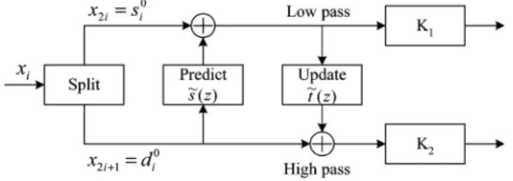
Daubechies and Sweldens first derived the lifting-based dis-crete wavelet transform [11], [12]. The lifting scheme can de-compose DWT filter bank into several lifting steps. As and are the low-pass and high-pass analysis filters; the polyphase matrix is defined as follows:
(1) The polyphase matrix can be factorized into a sequence of alternating upper and lower triangular matrices multiplied by a constant diagonal matrix, as shown in (2). Fig. 1 shows a general block diagram of the lifting-based structure
(2) The 9/7 filter has two lifting steps and one scaling step while the 5/3 filter can be regarded as a special case with single lifting
Fig. 1. Block diagram of the lifting scheme.
step. The detailed forward algorithm of the 9/7 filter is described from (3) to (10). First, the input sequences are split into even and odd parts, and . Second, the two splitting sequences are performed by two lifting steps. The outputs are denoted as and , where presents the stage of lifting step. Finally, through the normalization factors and , the low-pass and high-pass wavelet coefficients and can be obtained.
1) Splitting Step:
(3) (4) 2) Lifting Step:
(First Lifting Step)
predictor (5) updater (6) (Second Lifting Step)
predictor (7) updater (8) 3) Scaling Step:
(9) (10) The inverse sequences of and can be reconstructed by the inverse transform of the lifting scheme as follows:
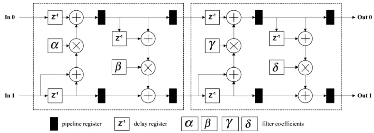
(11) (12) (13) (14) (15) (16) (17) (18) Several architectures [14], [15] have been proposed to di-rectly implement the lifting structures of the 5/3 and 9/7 filters. Fig. 2 depicts the direct mapping hardware architecture for the 1-D lifting-based DWT. The four pipeline stages are used to im-prove the processing time, but the critical path is still restricted by the computation of predictor or updater (i.e., two adders and one multiplier propagation delay). Moreover, it requires 32 pipeline registers to minimize the critical path to one multiplier delay. This constraint becomes a bottleneck for improving the working frequency of the conventional lifting structure.
Fig. 2. Direct mapping of 1-D lifting-based architecture for the 9/7 filter.
B. Modified Lifting-Based Discrete Wavelet Transform
Since the predictor or updater dominants the critical timing delay, we merge the predictor and updater stages into one single lifting step. By substituting (5) into (6), the lifting step can be expressed as one equation and each operation is computed by addition or multiplication as follows:
(19) In the second lifting step, (7) substitutes into (8) as the first lifting step. Since the output of the first lifting step are and , a factor is derived to let the output from the first lifting step can be computed directly. In this modification, (20) has the same form as (19), which indicates that the two lifting steps can be realized in the same architecture. The second lifting step equations are written as follows:
(20)
Finally, the scaling step is represented as follows:
(21) (22) The above modified equations require six constant multi-pliers , , , , , to perform the lifting and scaling steps. Both the primitive and modified algorithms have the same number of multipliers. Moreover, the modified algo-rithm reorders the long computation data path of the predictor and updater such that the arithmetic resources can be used more efficiently. More details are given in Section IV.
The inverse transform can be modified in the same way as the forward case. On the contrary, the inverse transform starts from the scaling step
(23) (24) The predictor and updater can be merged into a single equa-tion, as shown in (25). By substituting into the term, a new multiplier term, , is derived. It also reduces one multiplication operation for the input sequence
Similarly, a factor is derived such that and can be executed directly. The equations are rewritten as follows:
(26) Finally, to reconstruct the even part of the data, the coefficient
is applied to restore the output
(27) Both primitive and modified inverse DWT (IDWT) algo-rithms have six constant multipliers. In the modified case, the six multipliers are , , , , , and . In Section IV, we shall show that the modified algorithms for DWT and IDWT can be implemented more efficiently in the pipeline design method under the same arithmetic resources [14], [15].
III. PRECISIONANALYSIS
The floating-point numbers are converted into fixed-point representations in hardware implementation because floating-point operators require more computing time and larger chip areas. The precision issue of the finite wordlength is discussed for the lossless 5/3 and lossy 9/7 filters. The 5/3 filter applies the truncation operation to achieve the lossless coding. Thus, the primitive computations of single lifting step are calculated with truncation operations described as follows [1]:
(28) (29) To apply the merging scheme into the truncation operations, we rewrite (28) and (29) as (30) and (31), where the input se-quences, and , are all integer type
(30) (31)
Based on this modification, the flattened predictor and up-dater can be merged by substituting (30) into (31). As shown in (32), the result of is , where the operator keeps only two decimal bits of . The addition of 0.5 can be realized by the constant assignment of some bit
(32) In the similar way, the original inverse transform of the 5/3 filter proposed in JPEG2000 standard [1] can be modified as (33) and (34), where the input sequences of and all belong to integer. By applying the merging scheme into the flattened equations, the modified 5/3 filter with truncation operations can achieve the lossless coding through the finite-wordlength computations
(33) (34) The 9/7 filter is commonly used for the lossy compression of JPEG2000. To analyze the precision of the finite wordlength, it is important to discuss the overflow issue and the roundoff error. The overflow values can be bounded by the one-norm summa-tion from the constant coefficients. Equasumma-tions (19) and (20) de-scribe a series of additions for the computations of two lifting steps. By using the one-norm summation, the range of and of (19) are smaller than and , respectively, assuming the maximal value of input signals is . Similarly, by substituting the maximal values to the second lifting step shown in (20), the range of and are smaller than and . To avoid the instance of overflow, the large abso-lute coefficients, and can be further scaled. Table I shows the scaled coefficients of forward and inverse transform. Although larger scaling factors can even reduce the overflow instances, the finite wordlength precision would be decreased significantly. Considering the case where the maximum of pos-sible internal signals in the flipping and original lifting-based structures are bounded by and [22], the coefficients and are scaled by 2 such that the range for
and are smaller than (i.e., and
for and ). In the similar way, the inverse coefficients in (25) and (26) are scaled by 2 to allow the maximal values of and be and . From the above discussion,
TABLE I
COEFFICIENTS OF THE9/7 FILTERREPRESENTED IN THEBINARYFORMS
TABLE II
MAXIMUM ANDMINIMUMVALUES OFINTERNALREGISTERSWITHFB ISFIVE
for the process of DWT and IDWT, it is sufficient to use 2 bits more than the input signals for the internal data width to prevent the overflow problem.
The effect of the roundoff errors for the multilevel 2-D DWT and IDWT are simulated by various images [23] in terms of peak signal-to-noise ratio (PSNR), to determine the fixed-point representation. In the modified algorithm, the roundoff noise is mainly affected by the truncation operation before each fixed-point multiplication. Equation (35) presents the roundoff error model for the first lifting step, where the sequences of and are the noise signals [26]. This noise model can be applied to the second lifting step and scaling step. However, the quanti-zation errors of coefficients and the roundoff errors in each step would propagate to the further levels of DWT as well as the in-verse process, which are not included in this model
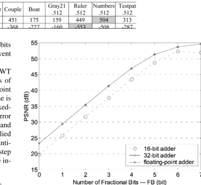
(35) To illustrate the overall effect of the truncation errors and de-termine the data path width, several 512 512 test images are simulated by performing five levels of DWT and IDWT under different decimal precision [18]. As presented in Fig. 3, the axis specifies the number of factional bit (FB) used for the truncation operation before each multiplication while axis de-notes the image quality in terms of PSNR. The quality values are based on the 8-bit raw data and 12-bit coefficients speci-fied in Table I. Compared with the floating-point adder, using the 32-bit adder can reach the same performance, since all the decimal precision is preserved (i.e., the number of decimal bit is set to 19) and no overflow instances occur in the internal sig-nals. The 16-bit adder only preserves the number of FB bit for the decimal precision and provides the inferior image quality. It
Fig. 3. Finite precision performance of different fractional bits (FB) with 12-bit coefficients.
Fig. 4. Proposed one-level 2-D DWT architecture.
may suffer the image degradation, if the number of integer bit is insufficient, e.g., FB is set to 7. Table II shows the maximal and minimal values of each addition and multiplication operation for five-level DWT and IDWT with FB equals 5. From Table II, it
Fig. 5. DFG of the first prediction and update step of the 9/7 filter.
is reasonable to choose 11 integer bits and 5 fraction bits for the fixed-point representation to avoid the overflow problem. With additional saturation circuits, one can use 10 integer bits and 6 fraction bits internal precision to improve the quality of general images.
IV. PROPOSED2-D DWT ARCHITECTURE
A. Overall Architecture
The proposed architecture performs the forward and inverse 2-D DWT transform in the column–row fashion. Fig. 4 depicts the overall 2-D DWT architecture, which includes three main components—the column processor, the transposing buffer, and the row processor. To carry out the one-level decomposition for an image, the proposed architecture executes the column processor, the transposing buffer and the row processor simulta-neously, where and represent the image height and width. Moreover, the row processor has to execute row-wise transform once enough column-processed data are obtained to decrease the internal memory size. Thereafter, the size external RAM is used to store the LL band output coefficients for the next level decomposition.
The primary objectives of the proposed 2-D DWT architec-ture are summarized as follows.
1) To shorten the data path of each pipeline stage: By reordering the primitive DWT data flow derived in Section II, the 1-D column processor can achieve one multiplier delay under the same arithmetic resources required for the primitive algorithm, but the number of pipeline registers are reduced from 32 to 20.
2) To minimize the internal memory size: Generally, the memory size required by 2-D DWT highly depends on the number of pipeline registers in 1-D architecture. Based on the modified data path, the proposed architecture can
partially execute the row-wise transform to minimize the size of temporal buffer for the row processor under the short pipeline data path constraint.
3) Flexibility in modularity: The three key components—the column processor, the transposing buffer, and the row pro-cessor—can be cascaded to implement the 5/3 and 9/7 fil-ters which have different lifting steps.
The remaining subsections discuss the details of the three main components and the overall 2-D DWT architecture.
B. Column Processor
The column processor can be regarded as a 1-D DWT pro-cessor acting on the column-wise image data. The proposed column processor is optimized in terms of the arithmetic cost and processing speed. Fig. 5 plots the detailed data flowgraph (DFG) for (19), which represents the calculations of one lifting step in the modified algorithm. The processor reads one input sample in each cycle, and then multiplies it by the corresponding coefficient in the following cycle. After each input datum is mul-tiplied, the rest of the calculation only requires several addition operations. The timing diagram of the DFG shows that only one multiplier and two adders are needed at each clock cycle for the computations, and the critical path between the pipeline regis-ters is mainly limited by one multiplier delay.
Based on the DFG, the optimal pipeline architecture for single lifting step can be derived, as shown in Fig. 6. One multiplier and two adders (1M2A) are defined as a processing element (PE) to implement a lifting step. The main issue of the controller design is to choose the valid input sources and output destination for each operation regularly. The gray parts of Fig. 5 indicate one multiplier and two adders are shared every two cycles. Besides, the computations of gray parts repeat the same data path every
Fig. 6. The proposed 1-D DWT architecture for column processor.
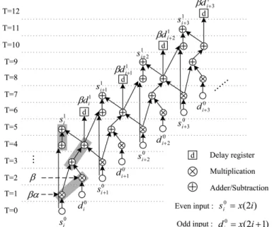
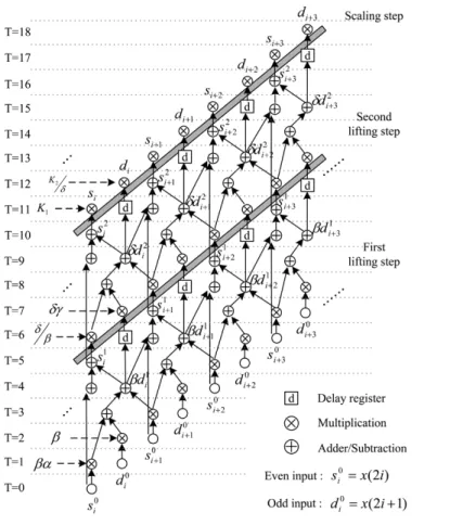
Fig. 7. DFG of modified 1-D lifting-based DWT of the 9/7 filter (i.e., use the unscaled coefficients to clarify the data path).
two cycles. Therefore, several multiplexers with predefined se-lections are applied to control the overall data path, as shown in Fig. 6. At the end of each lifting step calculation, a multiplexed register “Hi_delay_reg” is added to the output of “Hi_reg” to preserve the output order as input case.
Moreover, the data path of 9/7 filter is composed of two lifting steps and one scaling step, as shown in Fig. 7. Since both lifting steps have the same computational data path, the whole 1-D
Fig. 9. Block diagram of transposing buffer (image height:N).
TABLE III
DATAFLOW OFTRANSPOSINGBUFFER
Fig. 10. Input and output orders of transposing buffer.
PEs and one scaling multiplier. Fig. 8 shows the overall 1-D architecture of the 9/7 filter.
C. Transposing Buffer
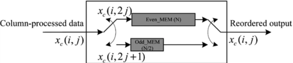
For an image, the transposing buffer stores the column-processed data and rearranges them into the specified order for the use of row processor. The memory organization is based on the line-based method [13], [19]. Fig. 9 shows the transposing buffer architecture. To illustrate the process, we use a 4 4 sample to describe the data flow. As shown in Table III, the transposing buffer firstly stores one complete even-column data to “Even_MEM” (from the zeroth to third clock cycle in this case). Once the first datum of the odd column is inputted, the transposing buffer starts to output the column-processed data in the raster order of two columns. Fig. 10 shows the input and output orders of the transposing buffer, where
indicates the column-processed data.
D. Row Processor
The row-wise transform can be considered as the transpose of the column process and is easy to perform in principle. In the hardware implementation, to reduce the internal memory re-quirement, the column-processed data have to be executed as
soon as possible. Moreover, the internal memory size of row processor highly depends on the pipeline registers of 1-D archi-tecture. The tradeoff between high speed and less memory is an important issue for the 2-D DWT architecture. Based on the modified algorithm, the column-processed data can be partially executed to decrease the internal memory size.
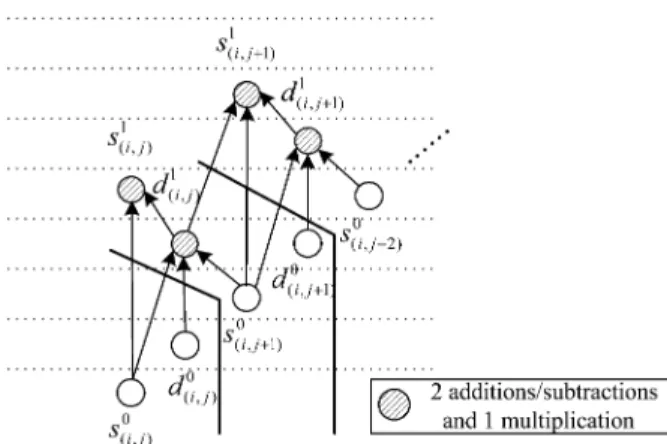
Fig. 11 indicates the ith row-wise data path of the modi-fied DWT algorithms. Once two column-processed data are col-lected, the ith row-wise transform is then partially performed and the results are temporarily stored in the “Sum_MEM ” and “T_MEM ”, where the index is from 0 to . That is, “Sum_MEM ” and “T_MEM ” are used to preserve the data path of each row transform and the data path is updated by the two new input data. Unlike the DFG of primitive algo-rithm shown in Fig. 12, the modified DFG requires only two, instead of three, input data to carry out the computations. With this advantage, a part of 1-D pipeline data path can be exe-cuted and the temporal results are saved to “Sum_MEM ” and “T_MEM ” to reduce the internal memory size.
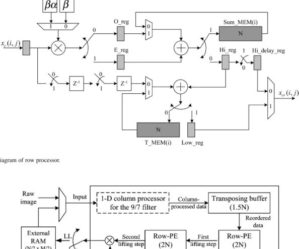
Fig. 13 presents the architecture of the row processor. “Sum_MEM ” and “T_MEM ” substitute the “Sum_reg” and “T_reg” of the column processor to preserve the data path of each row transform. The input order is in a raster format of
Fig. 11. Data path of theith row-wise transform.
Fig. 12. Data path of the primitive lifting-based algorithm.
one pair column data as shown in Fig. 10(b). Each input datum is multiplied by the corresponding coefficient. Then, the two memories read the previous data to execute the row transform and update the temporal results. Finally, the sequences
are the output coefficients of 2-D DWT.
Similar to the column processor, the data path of the row processor is controlled by the predefined multiplexers shown in Fig. 13. The main difference between the row processor and column processor is the control of temporal memory. The task of the two memories is to read the data from some address and then write the new data to the same address. That is, the memory address generator accumulates the address every two clock cy-cles: the first cycle is to restore the data path, and the second cycle is to update the temporal row transform. The boundary ex-tension can be solved by the shift operation, i.e., shift the output of “Hi_reg” and “E_reg” for the input and output boundary ex-tension, as shown in Fig. 11.
Similar to the 1-D case, the row-wise transform for the 9/7 filter can be implemented by cascading two row processors. Since the output timing is conformed to the input order as shown in Fig. 11, the second row processor can directly execute the output data from the first row processor. Thus, the overall 2-D DWT architecture of the 9/7 filter can be realized by cascading the column processor, transposing buffer, row processor and scaling multiplier, as shown in Fig. 14. First, raw data are pro-cessed by the 1-D column processor and the output data are then reordered by the transposing buffer. After one column delay, the row processors start to execute the row-wise transform. Fi-nally, a multiplier is used for the scaling step to produce the subband coefficients. The LL band outputs are stored to the ex-ternal memory and can be inputted to the processor for further decompositions.
E. Inverse Discrete Wavelet Transform (IDWT)
The modified equations for IDWT have the same form as those for DWT, so the data path of the inverse transform can be executed in a similar; way as the forward transform. The only difference of the inverse DFG is that one should insert “N/A” operations in the beginning and the end of data path. Fig. 15 depicts the inverse data path for one lifting step, which imple-ments (26). Similarly, the boundary extension can be solved by the shift operations and “Sum_reg” and “T_reg” can be ex-tended to the two memory banks for partially executing the in-verse column-wise transform. Like the forward processor, the proposed 2-D IDWT has the same components—the column processor, the transposing buffer and the row processor—and can be realized in the same architecture.
Fig. 13. Block diagram of row processor.
Fig. 14. One-level 2-D DWT architecture for the 9/7 filter.
F. Overall Performance
The hardware specifications of three main components are analyzed in Table IV. The row processor can be viewed as an extension of the column processor with memory size of . For the proposed 2-D DWT architecture, the critical path is mainly limited by a single multiplier delay or memory access time. After synthesizing and verifying the circuit, the 1-D data path can be performed at 200 MHz in TSMC 0.25 m 1P5M technology.
In applying the 5/3 filter of 1-D DWT, the total time required to calculate the length data is clock cycles. For an image, it requires clock cycles to perform one-level decomposition of 2-D DWT, where the cycles are the latency of the transposing buffer, and five is the number of pipeline stages for both the column and row proces-sors. Table V gives the detailed performances for both 5/3 and 9/7 cases, where and repre-sent the transposing latency of the column-processed data from the column processor to row processor for the 5/3 and 9/7 cases
TABLE IV
HARDWARESPECIFICATIONS OFTHREEMAINCOMPONENTS
TABLE V
PERFORMANCE OFPROPOSEDONE-LEVEL2-D DWT ARCHITECTURE
TABLE VI
COMPARISONS OFVARIOUS1-D DWT ARCHITECTURESWITH THE9/7 FILTER(T :THEDELAYTIME OF ANADDER,T :THEDELAYTIME OF AMULTIPLIER)
TABLE VII
COMPARISONS OFVARIOUSONE-LEVELLIFTING-BASED2-D DWT ARCHITECTURESWITH THE9/7 FILTER
V. COMPARISONS
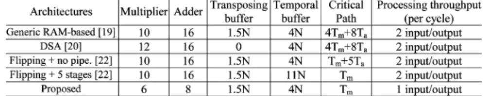
The lifting-based DWT generally has a lower computational burden and may need less memory than that required by the conventional filter banks. Like most 1-D DWT architectures with lifting structure, our architecture also uses the pipeline design method to increase the working frequency. Table VI compares several 1-D DWT architectures. For the direct im-plementation of the lifting structure, it uses six registers to achieve delay time [14]. Moreover, to achieve one multiplier delay, it requires 32 pipeline registers to min-imize the critical path. Systematic method was proposed to retarget for any DWT filters and it can decrease two registers compared to the direct mapping architecture for the 9/7 filter [17]. Flipping structure reduces the critical path by releasing the major computation path. The delay time can be decreased from to without any hardware overhead [22]. Consequently, it only requires 11 registers to achieve one multiplier delay. Based on the modified algorithm, the proposed architecture achieves the same timing constraint with 20 pipeline registers. Since this architecture is based on one
input data per clock cycle, it requires the half of arithmetic resources. As for the hardware implementation, the proposed architecture uses one programmable multiplier to perform the multiplications of two constant coefficients. Thus, the critical path of the proposed architecture would be longer than other architectures with one fixed-coefficient multiplier delay. To reduce the long critical path of the programmable multiplier, it is practical to design a specific multiplier sharing the hard-ware resources of the two fixed-coefficient multipliers for the proposed architecture. Finally, the proposed architecture can directly perform one lifting step computation for the 5/3 filter instead of the folded architecture with the parallel-to-serial converting circuit [15].
Moreover, the tradeoff between the pipeline stages and internal memory requirement is a critical issue of 2-D DWT implementation. Table VII presents several one-level 2-D DWT architectures. The generic RAM-based architecture focused on the memory organization for general 2-D architectures with line-based method [19]. Since the architecture directly extends the 1-D lifting structure to the 2-D implementation, the size of
TABLE VIII
COMPUTATIONCYCLE ANDMEMORY BANDWIDTH FORSEVERALONE-LEVEL 2-D ARCHITECTURES OF THE9/7 FILTER(IMAGESIZE:N 2 M, J-LEVELDECOMPOSITION)
TABLE IX
COMPARISONS OFMULTILEVELARCHITECTUREWITHLIFTING-BASEDDWTFOR THE9/7 FILTER
TABLE X
COMPARISONS OFCONVENTIONAL2-D DWT ARCHITECTURES OF THE9/7 FILTER
temporal buffer is determined by the number of pipeline reg-isters in the 1-D architecture. Dual-scan architecture (DSA) method scans two consecutive columns simultaneously to eliminate the transposing buffer [20]. Based on the direct implementation of the lifting structure, the critical path is dominated by delay time to achieve the temporal buffer with size. While more pipeline registers are ap-plied to minimize the critical path to a multiplier delay, the size of temporal buffer for both architectures would increase to .
Flipping structure provided a new method to ease the crit-ical path without hardware overhead [21], [22]. By requiring fewer pipeline registers for the flipped lifting structure, the size of temporal buffer can be reduced. Since the pipeline regis-ters of 1-D architecture fully turn into the internal memory of row-wise process, it requires temporal buffer with size to achieve one multiplier delay. Compared with the one-level 2-D architectures, the proposed architecture performs the modified algorithm to achieve one multiplier delay. Based on the merged algorithm, the row transform can be executed with only two column-processed data, instead of three required by the primi-tive algorithms [17], [18]. Therefore, the row processor carries out a part of pipeline data path of row-wise transform by using two column-processed data such that the 1-D pipeline registers do not fully turn into the temporal buffer of row processor. That is, only memory size of is required for each lifting step (i.e., “Sum_MEM” and “T_MEM” are size memories). Moreover, since the 9/7 filter is based on the two lifting steps, it requires
temporal memory with size to perform the row-wise trans-form with one multiplier delay.
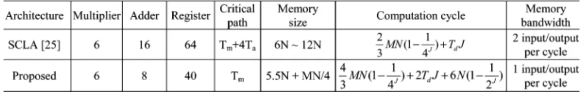
Table VIII compares the computation cycles of several one-level 2-D DWT architectures. The DSA method is based on two input pixels per cycle. Hence, the computation cycle of DSA is about the half of the other architectures based on the single input pixel per cycle ( is the pipeline latency from the input to output). Moreover, the hardware utilization of DSA architec-ture approaches to 100%, since the column processor and row processor can compute the same stage of DWT simultaneously through the dual scan method. ACT architecture is a general single-level 2-D architecture for several DWT filterbanks pro-posed in JPEG2000 [18]. To perform the different lifting steps, ACT architecture uses the general memory units and scheduler to calculate the various factorizing matrices. Compared with several related one-level 2-D architecture, the proposed archi-tecture is based on the one input pixel per cycle. As grows up, the transposing latency of the proposed architecture is close to cycles. The hardware utilization is slightly degraded by these transposing cycles relative small to the overall computa-tion cycle.
Table IX shows the comparison of the proposed architecture with a multilevel 2-D DWT architecture with lifting scheme. The SCLA method [16] combines the computations of the row and column matrices in the spatial domain to share the common coefficients of multiplications in the 9/7 filter for the 2-D DWT, increasing the arithmetic efficiency considerably. Compared with the proposed architecture, the SCLA-based architecture
[25] is based on the two input pixels per cycle. Thus, the com-putation cycle is about the half of the proposed architecture. To directly perform the 2-D DWT in the spatial domain, the SCLA-based architecture uses more registers to buffer the intermediate data. The critical path of the SCLA-based archi-tecture is dominated by the calculation of one multiplier and four adders between two working regions designed by several 3 3 register banks.
Table X compares the proposed architecture with several well-known ones based on the convolutional DWT for the 9/7 filter. The lifting-based DWT involves less computation than traditional DWT filter banks, so the number of required multipliers and adders decrease drastically. With respect to the memory requirement, the proposed architecture executes the one-level decomposition algorithm and still needs an addi-tional external memory to save the LL band data for performing the next decomposition. The control complexity of one-level 2-D architecture is simpler than the architectures based on RPA algorithm [6]. Finally, the proposed architecture implements the 5/3 and 9/7 filters by cascading the three key components.
Furthermore, the memory bandwidth may limit the throughput of the 2-D DWT processor. With the one-read and one-write port RAM, the proposed architecture defines one PE as one multiplier and two adders (1M2A) to perform the computation of single lifting step. At a higher bandwidth such as the two-input and two-output port RAM, the PE can be extended to two multipliers and four adders (2M4A) structure to achieve higher throughput [24].
VI. CONCLUSION
This study presents a high-performance and low-memory pipeline architecture for 2-D lifting-based DWT of the 5/3 and 9/7 filters. By merging the predictor and updater into one single step, we can derive an efficient pipeline architecture. Hence, given the same number of arithmetic units, the proposed architecture has a shorter pipeline data path. For the 2-D DWT, the internal memory size can be decreased by executing the two column-processed data and partially performing the row transform. Accordingly, not all pipeline registers of 1-D DWT turn into the internal memory of 2-D architecture. Thus, the proposed architecture can reach the same delay constraint with less internal memory compared to the related architecture. Finally, the 5/3 and 9/7 filters with the different lifting steps can be realized by cascading the three key components.
REFERENCES
[1] Information Technology—JPEG 2000 Image Coding System, ISO/IEC. ISO/IEC 15 444-1, 2000.
[2] G. Xing, J. Li, and Y. Q. Zhang, “Arbitrarily shaped video-object coding by wavelet,” IEEE Trans. Circuits Syst. Video Technol., vol. 11, no. 10, pp. 1135–1139, Oct. 2001.
[3] M. Martone, “Multiresolution sequence detection in rapidly fading chan-nels based on focused wavelet decompositions,” IEEE Trans. Commun., vol. 49, no. 8, pp. 1388–1401, Aug. 2001.
[4] S.-C. B. Lo, H. Li, and M. T. Freedman, “Optimization of wavelet decomposition for image compression and feature preservation,” IEEE
Trans. Med. Imag., vol. 22, no. 9, pp. 1141–1151, Sep. 2003.
[5] K. K. Parhi and T. Nishitani, “VLSI architectures for discrete wavelet transforms,” IEEE Trans. Very Large Scale Integr. (VLSI) Syst., vol. 1, no. 6, pp. 191–202, Jun. 1993.
[6] M. Vishwanath, “The recursive pyramid algorithm for the discrete wavelet transform,” IEEE Trans. Signal Process., vol. 42, no. 3, pp. 673–676, Mar. 1994.
[7] M. Vishwanath, R. M. Owens, and M. J. Irwin, “VLSI architectures for the discrete wavelet transform,” IEEE Trans. Circuits Systems II, Analog.
Digit. Signal Process., vol. 42, no. 5, pp. 305–316, May 1995.
[8] C. Chakrabarti and C. Mumford, “Efficient realizations of analysis and synthesis filters based on the 2-D discrete wavelet transform,” in Proc.
IEEE ICASSP, May 1996, pp. 3256–3259.
[9] C. Chakrabarti and M. Vishwanath, “Efficient realizations of the discrete and continuous wavelet transforms: From single chip implementations to mappings on SIMD array computers,” IEEE Trans. Signal Process., vol. 43, no. 3, pp. 759–771, Mar. 1995.
[10] N. D. Zervas, G. P. Anagnostopoulos, V. Spiliotopoulos, Y. An-dreopoulos, and C. E. Goutis, “Evaluation of design alternatives for the 2-D-discrete wavelet transform,” IEEE Trans. Circuits Syst. Video
Technol., vol. 11, no. 12, pp. 1246–1262, Dec. 2001.
[11] I. Daubechies and W. Sweldens, “Factoring wavelet transform into lifting steps,” J. Fourier Anal. Applicat., vol. 4, pp. 247–269, 1998. [12] W. Sweldens, “The new philosophy in biorthogonal wavelet
construc-tions,” Proc. SPIE, vol. 2569, pp. 68–79, 1995.
[13] C. Chrysafis and A. Ortega, “Line-based, reduced memory, wavelet image compression,” IEEE Trans. Signal Process., vol. 9, no. 3, pp. 378–389, Mar. 2000.
[14] J. M. Jou, Y. H. Shiau, and C. C. Liu, “Efficient VLSI architectures for the biorthogonal wavelet transform by filter bank and lifting scheme,” in
Proc. IEEE ISCAS, vol. 2, 2001, pp. 529–529.
[15] C. J. Lian, K. F. Chen, H. H. Chen, and L. G. Chen, “Lifting based discrete wavelet transform architecture for JPEG2000,” in Proc. IEEE
ISCAS, vol. 2, 2001, pp. 445–445.
[16] H. Meng and Z. Wang, “Fast spatial combinative lifting algoirthm of wavelet transform using the 9/7 filter for image block compression,”
Electron. Lett., vol. 36, no. 21, pp. 1766–1767, Oct. 2000.
[17] C. T. Huang, P. C. Tseng, and L. G. Chen, “Efficient VLSI architec-tures of lifting-based discrete wavelet transform by systematic design method,” in Proc. IEEE ISCAS, vol. 5, May 2002, pp. 565–568. [18] K. Andra, C. Chakrabati, and T. Acharya, “A VLSI architecture for
lifting-based forward and inverse wavelet transform,” IEEE Trans.
Signal Process., vol. 50, no. 4, pp. 966–977, Apr. 2002.
[19] P. C. Tseng, C. T. Huang, and L. G. Chen, “Generic RAM-based archi-tecture for two-dimensional discrete wavelet transform with line-based method,” in Proc. Asia-Pacific Conf. Circuits and Systems, 2002, pp. 363–366.
[20] H. Liao, M. K. Mandal, and B. F. Cockburn, “Efficient architectures for 1-D and 2-D lifting-based wavelet transforms,” IEEE Trans. Signal
Process., vol. 52, no. 5, pp. 1315–1326, May 2004.
[21] C. T. Huang, P. C. Tseng, and L. G. Chen, “Flipping structure: An effi-cient VLSI architecture for lifting-based discrete wavelet transform,” in
Proc. IEEE ISCAS, 2002, pp. 383–388.
[22] , “Flipping structure: An efficient VLSI architecture for lifting-based discrete wavelet transform,” IEEE Trans. Signal Process., vol. 52, no. 4, pp. 1080–1089, Apr. 2004.
[23] USC-SIPI Image Database. [Online]. Available: http://sipi.usc.edu/ser-vices/database/
[24] B. F. Wu and C. F. Lin, “A rescheduling and fast pipeline VLSI architec-ture for lifting-based discrete wavelet transforms,” in Proc. IEEE ISCAS, vol. II, May 2003, pp. 732–735.
[25] L. Liu, X. Wang, H. Meng, L. Zhang, Z. Wang, and H. Chen, “A VLSI architecture of spatial combinative lifting algorithm based 2-D DWT/IDWT,” in Proc. 2002 Asia-Pacific Conf. Circuits and Systems, vol. 2, Oct. 2002, pp. 299–304.
[26] K. K. Parhi, VLSI Digital Signal Processing Systems: Design and
Bing-Fei Wu (S’89–M’92–SM’02) was born in
Taipei, Taiwan, R.O.C., in 1959. He received the B.S. and M.S. degrees in control engineering from National Chiao Tung University (NCTU), Hsinchu, Taiwan, R.O.C., in 1981 and 1983, respectively, and the Ph.D. degree in electrical engineering from the University of Southern California, Los Angeles, in 1992.
Since 1992, he has been with the Department of Electrical Engineering and Control Engineering, where he currently is Professor. As an active in-dustry consultant, he is also involved in the chip design and applications of the flash memory controller and 3C consumer electronics in multimedia systems. The research has been honored by the Ministry of Education as the Best Industry-Academics Cooperation Research Award. He founded and served as the Chair of the IEEE Systems, Man and Cybernetics Society Taipei Chapter in Taiwan, 2003. He has been the Director of The Research Group of Control Technology of Consumer Electronics in the Automatic Control Section of National Science Council (NSC), Taiwan, from 1999 to 2000. His research interests include vision-based intelligent vehicle control in Intelligent Transportation Systems, multimedia signal compression, and wavelet analysis and applications.
Prof. Wu received the Distinguished Engineering Professor Award from Chi-nese Institute of Engineers in 2002; the Outstanding Information Technology Elite Award from Taiwan Government in 2003; the Golden Linux Award in 2004; the Outstanding Research Award in 2004 from NCTU; the Research Awards from NSC in the years of 1992, 1994, 1996–2000; the Golden Acer Dragon Thesis Award sponsored by the Acer Foundation in 1998 and 2003, respectively; the First Prize Award of the We Win (Win by Entrepreneurship and Work with Innovation & Networking) Competition hosted by Industrial Bank of Taiwan in 2003; and the Silver Award of Technology Innovation Competition sponsored by the Advantech Foundation in 2003.
Chung-Fu Lin (S’02) was born in Taipei, Taiwan,
R.O.C., in 1977. He received the B.S. degree in mechanical engineering from National Central University, Taiwan, R.O.C., in 1999 and the M.S. degree in mechanical engineering from National Chiao Tung University, Taiwan, R.O.C., where he is currently working toward the Ph.D. degree in the Department of Electrical and Control Engineering.
His research interests include multimedia applica-tion, VLSI design and implementation.
Mr. Lin received the Macronix Golden Silicon Honorable Mention in the Third Semiconductor and Application Competition sponsored by Macronix International Co., Ltd., in 2003.