國
立
交
通
大
學
電信工程研究所
碩
士
論
文
共存干擾之管理
On the Management of In-Device Coexistence
Interference
研 究 生:賴勇先
指導教授:蘇育德 教授
謝世福 教授
共存干擾之管理
On the Management of In-Device Coexistence Interference
研 究 生:賴勇先 Student:Yung-shian Lai
指導教授:蘇育德 Advisor:Dr. Yu T. Su
謝世福 Dr. Shih F. Hsieh
國 立 交 通 大 學
電信工程研究所
碩 士 論 文
A ThesisSubmitted to the Institute of Communications Engineering in Partial Fulfillment of the Requirements
for the Degree of Master of Science
in
Communications Engineering at the
National Chiao Tung University
July 2012
Hsinchu, Taiwan
共存干擾之管理
學生:賴勇先
指導教授
:蘇育德博士
謝世福博士
國立交通大學電信工程研究所碩士班
摘
要
為了完全利用有多個無線電系統共存的異質網路,使用者應該有能力去選擇最有效率的 系統;其中效率的測度為單位傳輸功率的吞吐量。這樣一來,使用者裝置需搭載多種傳收器以 因應不同的環境並選擇當下最適當的系統。例如:藉由選擇無線區域網路(Wi-Fi)或藍芽 (Bluetooth)來代替一般的巨型蜂巢式系統以連接公眾網路,減少網路端和用戶端的單位頻寬 功率消耗。一個擁有多種無線電傳輸能力的使用者設備,也可以被當作大型和小型無線系統之 間的中繼站,來降低大型無線網路流量的負載。 在上述的應用中,除非這些無線電使用的頻帶間距夠遠,否則會有嚴重的干擾問題。這 是因為正在傳送信號的無線電會干擾到其他無線電的接收端。找出消除此共存干擾的解決方案 正是這篇論文的主要目的。我們將集中討論在長期演進發展技術(LTE)和 Wi-Fi 之間的共存 干擾問題。這個議題在第三代合作夥伴計劃(3GPP)的標準 36.816 [1]已經被密集的討論過, 主要可歸納為三種候選方案:功率控制(PC)、分頻多工(FDM)、分時多工(TDM)等技術。 藉由兼容這三者的優點,即同時利用 FDM 方案使兩個無線電操作頻段盡可能遠離、藉由 TDM 避免多個無線電同時啟用並將傳送功率控制在可容忍的範圍內,可以得到一個最佳解決方案。 然而,如此做法可能因為與現有的標準相容性的問題而變得不可行,故尚需更進一步的探討。 非連續接收機制(DRX)原本設計是為了省電,使用者只能在每周期的一段固定時間內 進行通訊,而在剩下的時間睡眠來達到省電的效果。而這樣的周期性的開關機制卻讓二個無線 電可以分別在不同時間進行通訊。因為 DRX 已納入 LTE 標準,相容性的考量讓以 DRX 為基 礎的 TDM 解決方顯得較為實用。但由於 DRX 機制會將時間資源分別給 LTE 和 Wi-Fi 傳收端, 使得二者的系統吞吐量都下降。因此,我們不希望太早啟用這種機制以盡可能地避免吞吐量下 降;另一方面,如果太晚啟用,沒有被處理的共存干擾又會降低訊號干擾雜訊比(SINR)並 且導致封包遺失。我們試著找出啟動與解除 DRX 機制的最佳時間點,並且在正確的時間點傳
i 送觸發訊號給基地台。我們利用在適當時間區間量測到的 SINR 來決定是否要啟上述機制並回 報 DRX 的相關參數給基地台。根據模擬結果,在 LTE 下傳吞吐量的效能上,我們提出的方法 會比以下另外二種方式來得好:第一種是當 Wi-Fi 一開啟就立即啟用 DRX 機制;第二種則是 不啟用任何的共存干擾解決方案。我們的方法不但可以同時滿足 LTE 和 Wi-Fi 的吞吐量要求, 也可使 LTE 下傳吞吐量達到最大。 正如前述,為了要決定何時要啟動 DRX 機制,我們需要量測 SINR 的比值,因此如何在 實體層精準地量測 SINR 是我們要探討的另一個議題。我們利用二階回歸模型[3]來同時估測通 道增益和其對應的 SINR。根據模擬結果,這種做法會比傳統的最小平方誤差通道估計器效能 更好。 我們分別用電腦模擬和數學分析來估算和比較開啟 DRX 後 LTE 和 Wi-Fi 吞吐量,根據這 些分析結果我們可以評價各種 DRX 參數對於吞吐量的影響。我們推導得到了傳送一個封包所 費時間的機率密度函數,以及其相關的變異數以及平均吞吐量。雖然 Wi-Fi 系統只可在 DRX 的睡眠期間啟動,它可以趁這期間結束前,根據已知剩餘可用的時間調整封包大小。在這種情 況下,Wi-Fi 平均的吞吐量大約會等於睡眠時間和 DRX 週期的比值,此理論推導也藉由模擬 得到驗證。另外,我們採用 FD-PF[15]公平資源排程機制來進行 LTE 吞吐量分析,模擬結果符 合 LTE 可用時間比例與吞吐量一同增加的預期。我們可以從模擬結果發現此排程機制所導致 的一些特徵,並利用它們來建立可同時滿足 LTE 和 Wi-Fi 吞吐量需求的 DRX 參數選擇方針。
誌
謝
人生第一個求學階段在交通大學電信工程研究所總結,一開始我要感謝指導教授 蘇育德 博士的指導,在多次的嘗試和失敗中,由於老師給予的意見使得理論和分析能順利進行。除了 專業知識外,在碩班 meeting 時多了時事問答、演講者介紹、生活分享這些流程,使得實驗事 相處更融洽,並且得知老師在專業上的想法和經歷時,思考和待人處事方面可以更成熟。 另外還要感謝林坤昌學長,在我碩一的時候辛苦的指導,給予研究很多方向以及建議,還 有做人處事的態度以及人生樂觀豁達的觀念。以及感謝碩二接計劃時,幫助我很多的 MTK 學長 傅宜康,還有計劃上花最多時間跟我討論的學長周建銘,還有指導我研究的學姐宋光玉。再來 要感謝 tofar 學長幫我預口試,感謝海格在研究上給予的建議,感謝松鼠常常陪我打桌球,感 謝小劉幫我修論文摘要,感謝科夆、武修、志宇,西瓜…等學弟妹和學長姐在研究上的鼓勵, 讓我能順利在最後半年把論文完成。 最後要感謝我家人的支持以及關心,因為有他們在背後支持,才有辦法持續的堅持下去。 賴勇先謹致 于新竹國立交通大學
On the Management of In-Device Coexistence
Interference
Student : Yung-Shian Lai Advisor : Yu T. Su and Shih F. Hsieh
Department of Communications Engineering National Chiao Tung University
Abstract
To make the most of a heterogeneous network in which multiple radio systems co-exist, an user equipment (UE) should have the capability to select the most efficient system where the efficiency is measured by the throughput/power ratio. Such a capa-bility requires that UEs are equipped with built-in multiple transceivers so that it can adapts to the environment and choose, for example, Wi-Fi or Bluetooth, to connect to the network instead of a regular macro-cellular system, resulting in power/bandwidth saving for both the UE and network. A device with such multiple radio capability can also be used as a relay between a macro system and a small cell to offload the network traffic.
A serious interference problem arises when applications similar to the latter scenario are called for unless the assigned bands for these radios are sufficiently separated. When both transceivers in the same device are active, the transmitting radio signal will in-terfere the other radio’s receiver. It is the purpose of this thesis to find solutions for mitigating this in-device coexistence interference(IDCI). We focus on IDCI between LTE and Wi-Fi systems. This particular issue has been intensively discussed in 3GPP spec-ification 36.816 [1] from which three major candidates solutions have emerged, namely, Power control solution, Frequency Division Multiplexing (FDM) solution, and Time Di-vision Multiplexing (TDM) solution. An optimal one would bear the flavors of all three
approaches, i.e., one invokes the FDM solution to select the available bands as far apart as possible, and the TDM solution to avoid simultaneous activation while control the transmit power to a tolerable range. Unfortunately, such a solution is often not real-izable as it may not compatible with the existing LTE standard and modifications are needed.
As a result, the Discontinue Reception (DRX) based TDM solution is much more practical as DRX had been standardized by LTE. DRX is originally designed for energy-saving purpose that allows only a fractional wake-up interval within each predetermined period. However, such a periodic on-off clock can be used to serve two radios in disjoint time intervals.
Since the DRX based solution divides the time resources into two parts for the LTE and Wi-Fi transceivers, it will degrade the throughput of both systems. Hence we do not want to activate such an IDCI solution too early to avoid degradation of throughput as much as possible. On the other hand, if we invoke the IDCI solution too late, the coexistence interference will reduce SINR and cause packet loss. In this study, we try to optimize the activation time for the DRX based solution, sending a trigger signal to eNB at the right time. We also find the optimal deactivation time. Based on measured SINR over a proper time period, we decide whether or not to trigger the IDC solution and report the associated DRX parameters to the serving eNB.
For determining when to trigger the DRX based solution, we need to measure the signal quality such as Signal to Interference plus Noise Ratio (SINR). Hence, how to measure SINR accurately in the physical layer is another issue we want to discuss. We use the regression model based approach of [3] to jointly estimate the channel gain and the correspondent SINR. It is shown that this approach outperforms the conventional least square (LS) based channel estimator.
Our simulations indicate that the LTE DL throughput performance of the proposed solution is better than the other two alternatives: the first one triggers the DRX based
solution whenever WiFi is on while the second one does not employ any IDCI solu-tion. Our method not only satisfies the LTE and WiFi throughput constraints but also maximizes the LTE DL throughput.
The WiFi and LTE throughput performance is estimated by both computer simu-lation and analysis. The analytical results enable us to assess the effects of the DRX parameters on the throughput performance. We derive the probability density function (pdf) of the packet transmission time and evaluate the mean throughput and the associ-ated variance. As WiFi can use only the off-duration of the DRX clock, it can adjust the packet size according the timing information. In that case, the average throughput is approximately equal to the fraction of the off-duration. The theoretical derivations are verified by simulations. For the LTE throughput analysis, we adopt the fairness-aware FD-PF scheduling scheme. The simulation results are consistent with the anticipation that the throughput improves with the increase availability of the LTE time resource. We establish guidelines for the system to select appropriate DRX parameters to meet both LTE and WiFi’s throughput requirements.
Contents
English Abstract i
Contents iv
List of Figures vii
List of Tables xii
1 Introduction 1
1.1 The coexistence interference problem . . . 1
1.2 Operation Scenarios for IDCI . . . 2
1.2.1 IDCI caused by coexistence of LTE and WiFi . . . 3
1.2.2 IDCI Arisen from Coexistence of LTE and Bluetooth . . . 7
1.2.3 LTE coexisting with GNSS . . . 8
1.2.4 Summary of in-device coexistence interference scenarios . . . 8
1.3 Coexistence interference avoidance . . . 9
1.3.1 Coexistence operation modes . . . 9
1.3.2 Frequency Division Multiplexing (FDM) . . . 11
1.3.3 Time Division Multiplexing (TDM) . . . 12
1.3.4 Power control (PC) . . . 15
1.3.5 Summary for coexistence interference problem solution . . . 16
2.1 Scenario and assumptions . . . 19
2.1.1 A LTE and WiFi coexistence model: Operation and Interference . 20 2.2 Problem formulation . . . 25
2.2.1 A typical IDCI avoidance procedure . . . 25
2.2.2 Motivation for IDCI solution trigger study . . . 27
3 Simulation Based TDM Solution–Operation Assumptions 28 3.1 WiFi operation assumptions . . . 28
3.1.1 CSMA/CA with RTS/CTS transmission scheme . . . 28
I The steps for 802.11 CSMA as follows: . . . 28
I The scheme for CA as follows: . . . 28
3.1.2 Relationship between the number of WiFi users and IDC user . . 31
3.2 LTE frame structure and operation assumptions . . . 31
3.3 LTE downlink SINR . . . 32
3.4 LTE downlink throughput . . . 34
4 Appropriate Occasion To Trigger TDM Solution 37 4.1 The effect of WiFi/LTE parameters and WiFi/LTE throughput . . . 37
4.2 Proposed algorithm method . . . 46
4.3 Simulation result and summary . . . 51
4.4 SNR and SINR estimations . . . 54
4.4.1 Importance for SINR estimation . . . 54
I Motivation . . . 54
I System operating model . . . 54
4.4.2 Channel estimation . . . 56
I Least square channel estimation + linear interpolation . 56 I Model based channel estimation: . . . 56
4.4.3 SNR estimation . . . 58
4.4.4 Numerical examples . . . 59
5 LTE/WiFi Throughput Analysis 67 5.1 WiFi throughput analysis . . . 67
5.1.1 Introduction of WiFi protocal . . . 67
5.1.2 Introduction of WiFi system throughput analysis . . . 69
5.1.3 WiFi throughput analysis for single user . . . 72
5.1.4 Simulation result . . . 89
5.2 WiFi throughput analysis with DRX . . . 95
5.3 LTE throughput analysis . . . 100
5.3.1 Introduction of scheduling scheme . . . 100
5.3.2 Scenario . . . 102
5.3.3 Simulation result for LTE throughput . . . 104
6 Conclusion 113
Bibliography 116
List of Figures
1.1 Coexistence interference within the same UE. . . 2
1.2 Coexistence interference from the in-device ISM transmitter to the E-UTRA receiver. . . 3
1.3 3GPP frequency bands around the ISM band. . . 3
1.4 LTE + WiFi portable router. . . 4
1.5 LTE + WiFi offload. . . 6
1.6 Uncoordinated mode. . . 9
1.7 Coordinated within UE only. . . 10
1.8 Coordinated with network level. . . 10
1.9 Potential solutions to move LTE signal away from ISM band. . . 11
1.10 Move WiFi radio signal away from LTE frequency band. . . 12
1.11 Time division multiplexing for coexistence interference avoidance. . . 13
1.12 Example of UE suggested TDM pattern. . . 14
1.13 Example of DRX configured by eNB to enable TDM. . . 15
1.14 DRX scheme. . . 15
1.15 LTE power control for coexistence interference mitigation. . . 16
1.16 ISM power control for coexistence interference mitigation. . . 17
2.1 Interaction between LTE and WiFi models. . . 21
2.2 DRX procedure. . . 22
2.3 A typical IDCI avoidance procedure. . . 26
3.1 DCF with the CSMA/CA protocol. . . 29
3.2 Data frame for the RTS/CTS scheme. . . 30
3.3 IDC user contends with other users. . . 30
3.4 TDD frame structure. . . 31
3.5 TDD configuration. . . 32
3.6 LTE Resource Block (RB) structure. . . 33
3.7 OFDM subcarrier spacing. . . 33
3.8 SINR versus BLER with different MCS level. . . 35
3.9 4 bit CQI table. . . 36
4.1 IDC indication for LTE DL. . . 37
4.2 Number os WiFi users versus Normalized throughput ratio. . . 39
4.3 Number of WiFi users and WiFi UL activity.. . . 40
4.4 WiFi transmission rate versus WiFi/LTE throughput (Full buffer case) . 40 4.5 WiFi transmission rate versus WiFi UL ratio (Full buffer case) . . . 42
4.6 WiFi transmission rate versus WiFi/LTE throughput (traffic 11Mbps) . . 43
4.7 WiFi transmission rate and WiFi UL ratio (traffic 11Mbps) . . . 43
4.8 WiFi transmission rate versus WiFi/LTE throughput (traffic 5.5Mbps) . 44 4.9 WiFi transmission rate and WiFi UL ratio (traffic 5.5Mbps) . . . 44
4.10 Different DRX parameter for normalized throughput . . . 46
4.11 WiFi transmission rate and WiFi UL ratio. . . 47
4.12 Proposed algorithm procedure . . . 48
4.13 Select appropriate parameters . . . 49
4.14 Classify the LTE subframes to two groups for without and with WiFi interference . . . 50
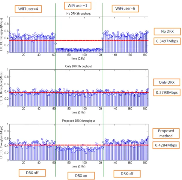
4.15 WiFi uplink time and LTE DL throughput (no DRX/Only DRX/Proposed) 51 4.16 Number of WiFi user is time varying versus LTE DL throughput) . . . . 52
4.18 Procedure for SINR estimation. . . 55
4.19 Pilot position on resource element. . . 55
4.20 observed region. . . 58
4.21 Channel gain for different symbols. . . 60
4.22 Channel estimation over frequency and time domain. . . 61
4.23 SNR vs BER for different channel estimation method at UE velocity of 30km/hr. . . 61
4.24 Compare different SNR estimation method with real SNR at UE velocity of 30km/hr. . . 62
4.25 Compare NMSE for different SNR estimation method at UE velocity of 30km/hr. . . 62
4.26 Compare different SNR estimation method with real SNR at UE velocity of 80km/hr. . . 63
4.27 Compare NMSE for different SNR estimation method at UE velocity of 80km/hr. . . 64
4.28 Compare different SNR estimation method with real SNR at UE velocity of 80km/hr and block size of time is 4(RBs). . . 65
4.29 Compare NMSE for different SNR estimation method at UE velocity of 80km/hr and block size of time is 4(RBs). . . 65
5.1 Based structure for time sychronization. . . 68
5.2 Procedure of WiFi signal transmission. . . 69
5.3 The position of NAV in a data frame. . . 69
5.4 Markov Chain model for the backoff window size. . . 70
5.5 Ts, duration for transmitting a packet successfully . . . 73
5.6 Tc, duration for transmitting a packet fail. . . 73
5.7 The route of a packet successful transmission on Markov Chain model for the backoff window. . . 74
5.8 State transition when the backoff timer counter is not equal to zero. . . . 74
5.9 Random variable of transition time interval. . . 75
5.10 Mean of transmission time for a packet with different number of users, CWmax=10. . . 89
5.11 Mean of transmission time for a packet with different number of users, CWmax=9. . . 90
5.12 Mean of transmission time for a packet with different number of users, CWmax=8. . . 90
5.13 Variance of transmission time for a packet with different number of users, CWmax=10. . . 91
5.14 Variance of transmission time for a packet with different number of users, CWmax=9. . . 92
5.15 Variance of transmission time for a packet with different number of users, CWmax=8. . . 92
5.16 WiFi throughput for derivation and simulation, CWmax=10. . . 93
5.17 WiFi throughput for derivation and simulation, CWmax=9. . . 94
5.18 WiFi throughput for derivation and simulation, CWmax=8. . . 94
5.19 Switch between LTE and WiFi on DRX scheme. . . 95
5.20 WiFi throughput with DRX for derivation and simulation, Ton=20ms. . . 96
5.21 WiFi throughput with DRX for derivation and simulation, Ton=40ms. . . 97
5.22 WiFi throughput with DRX for derivation and simulation, Ton=60ms. . . 97
5.23 WiFi throughput with DRX for derivation and simulation, Ton=80ms. . . 98
5.24 WiFi throughput with DRX for derivation and simulation, Ton=100ms. . 98
5.25 WiFi throughput with different DRX parameters. . . 99
5.26 WiFi throughput with different DRX parameters. . . 101
5.27 Cases for different distance between BS and IDC user. . . 103 5.28 The probability density function with different distance when users appear.103
5.29 Compare LTE throughput with DRX and without DRX in different dis-tance of BS. . . 104 5.30 Compare LTE throughput with DRX and without DRX on DRX cycle
128ms. . . 105 5.31 Compare LTE throughput with DRX and without DRX on DRX cycle
160ms. . . 106 5.32 Compare LTE throughput with DRX and without DRX on DRX cycle
256ms. . . 107 5.33 Compare LTE throughput with DRX and without DRX on DRX cycle
320ms. . . 107 5.34 On duration vs. throughput for different DRX cycle on distance 200m. . 108 5.35 On duration vs. throughput for different DRX cycle on distance 800m. . 108 5.36 On duration vs. throughput for different DRX cycle on distance 1100m. . 109 5.37 DRX ratio vs. throughput for different DRX cycle on distance 200m. . . 110 5.38 DRX ratio vs. throughput for different DRX cycle on distance 800m. . . 111 5.39 DRX ratio vs. throughput for different DRX cycle on distance 1100m. . . 111 5.40 DRX ratio vs. throughput. . . 112
List of Tables
4.1 Simulation assumption for LTE and WiFi parameters. . . 39 4.2 Simulation assumption. . . 59
Chapter 1
Introduction
1.1
The coexistence interference problem
The LTE-A (Long Term Evolution-Advanced) mobile standard supported by 3GPP (3rd Generation Partnership Project) shall provide downlink data rates greater than or equal to 1 Gbps and 100 Mbps for low and high mobilities, respectively. LTE downlink shall adapt the Orthogonal Frequency Division Multiple Access (OFDMA) technology while Single Carrier Orthogonal Frequency Division Multiple Access (SC-OFDMA) is the uplink air interface technology. Both technologies provide many attractive features that include robustness against frequency selective fading, high spectral efficiency, great flexibility in radio resource allocation and scheduling.
Due to the increasing popularity and proliferation of the Wireless Local Area Net-works (WLANs), it has become a desired feature that a mobile phone can access to both cellular and WLAN systems. One prefers to make a phone call through cellular system, access the Internet through WiFi, and connect a portable handset (earphone) through Bluetooth. In some applications, one would like to access these heterogenous systems simultaneously which unfortunately causes inter-radio interference. This is because the operation band of the so-called industrial, scientific, and medical (ISM) band and band 40 of LTE are close to one another, the coexistence of two types of radio transceivers
will result in adjacent channel interference. We refer to the interference issue associated with this scenario as In-device coexistence interference (IDCI) problem.
Figure 1.1: Coexistence interference within the same UE.
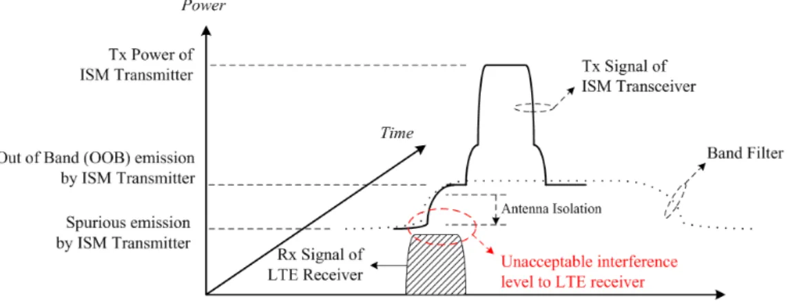
Fig. 1.1 shows an example in which many radio transceivers are embedded in the same UE chip. The transmit power from a radio transmitter is often much higher than the power received by another radio while both are located in the same chip. Because of insufficient frequency separation and isolation between the transmit and receive units, the transmit signal causes serious interference. The current filter technology can not provide enough rejection and it is difficult to solve interference problem by RF design. Alternative methods by baseband design should therefore be considered. The above in-device coexistence interference (IDCI) problem in power, time, and frequency domains is illustrated in Fig. 1.2. An ISM band transmitter sends signal to AP, and the LTE receiver receives signal from eNB at the same time. Typically, the spurious emission by the ISM transmitter is much higher than the received LTE signal strength.
Fig. 1.3 plots the 3GPP frequency bands around 2.4GHz ISM band. Three ra-dio technologies discussed in 3GPP 36.816 [1] result in coexistence with LTE, namely, WiFi, Bluetooth, and GNSS. We discuss these three operating scenarios in the following section.
Figure 1.2: Coexistence interference from the in-device ISM transmitter to the E-UTRA receiver.
Figure 1.3: 3GPP frequency bands around the ISM band.
1.2.1
IDCI caused by coexistence of LTE and WiFi
When an IDC user transmits a WiFi waveform and receive data from the LTE network to provide real time traffic service, WiFi uplink data to AP will interfere with LTE receiving data from eNB, and LTE uplink data will also interfere with the WiFi receiving data from AP because LTE band 40 operates at TDD mode, and it will uplink and downlink data at the same frequency band. WiFi has 14 channels in ISM band, and each channel bandwidth is 22MHz. Channel 1 starts with 2401MHz, and channel 14 ends at 2495MHz. Each channel separates from adjacent channel by 5MHz. There is an exception in channel number 14 where separation is 12MHz. Channel number 14 is defined beyond ISM band,
and it is only used in Janpan. The transmitter of WiFi will affect receiver of LTE band 40 and vice-versa. Since LTE band 7 is a FDD band, it will affect WiFi receiver. However, WiFi doesn’t affect LTE receiver at LTE band 7 downlink.
Figure 1.4: LTE + WiFi portable router.
1.2.1.1 LTE + WiFi portable router
Fig. 1.4 can express this scenario. In this figure, it shows the situation for LTE downlink data from eNB to IDC-UE and for WiFi of IDC-UE downlink data to many stations, and the transmission of WiFi will interfere LTE receiver. UE uses LTE which is considered as a backhaul link to access the Internet to download data from network, and the UE shares the data by WiFi to other local WiFi stations which connect with it. Therefore, the UE becomes a portable AP which has full control on frequency chan-nel and transmitting power. The UE can move WiFi signal away from LTE band by itself. If this is not sufficient to solve IDCI problem, UE can inform eNB and require an IDCI solution. If we use TDM solution to solve the IDCI problem, it will allocate scheduled period and unscheduled period for LTE. During DL from eNB to UE, the worst case is that if a packet arrives at the eNB at the beginning of the LTE
unsched-uled period, the resulting delay is the sum of the LTE unschedunsched-uled period (waiting for LTE scheduling) and the LTE scheduling period (waiting for WiFi scheduling). It is the delay which begins with eNB receiving packet from Internet and ends with WiFi starting to transmit this packet to the station. The situation is similar to the UL. The scheduling/unscheduled periods can be made as small as 1 ms to minimize delay, but it is unusable because it doesn’t consider the impact on retransmissions and other timelines on both LTE and WiFi, and it also can’t satisfy WiFi transmission time which may excess 1ms. Therefore, the scheduling/unscheduled periods should be balanced between the timeline requirements and the needs of the specific Quality of service (QoS). The scheduling periods and unscheduled periods should use the following guidelines:
1. Scheduling periods and unscheduled periods should be typically not more than [20-60] ms.
2. The scheduling and unscheduled periods should be large enough to conform rea-sonable operation of the LTE and WiFi timelines.
3. Since LTE has typically lower data rate than the WiFi link, the LTE scheduling periods should be longer than the unscheduled periods in order to achieve roughly the same throughput on both links.
The coexistence interference case 1-3 of section 1.2 may happen in this scenario.
1.2.1.2 LTE + WiFi offload
Fig. 1.5 can express this scenario. It shows the situation for WiFi uplink data to AP and for LTE downlink data from eNB to UE, and the transmission of WiFi will interfere with LTE receiver. LTE UE can offload traffic from LTE to WiFi, and the WiFi transceiver of the UE operates as a terminal (not AP) in infrastructure mode. For example, UE performs video conference. The video stream can be divided into image packets and VoIP packets. And it uses WiFi radio to transmit image packets for
Figure 1.5: LTE + WiFi offload.
offloading load of LTE and uses LTE radio to transmit VoIP packets for guaranteeing Qos (delay). Because WiFi radio is not AP, it is difficult for the WiFi radio to change the configured frequency channel. In addition, the WiFi radio has to keep listening to the beacon signal transmitted from WiFi AP for maintaining connection. In this scenario, if we use time domain solution, the requirements for the scheduling period and the unscheduled periods will be analyzed as following three observations:
First observation is that UE in WiFi client mode must receive WiFi beacon. In order to receive beacons properly, the LTE unscheduled period needs to align with the WiFi beacons. Besides, in order to provide for beacon reception, the scheduling period of LTE should be no longer than 100ms.
Second observation is that the packet from network can choose one link (WiFi for offload packets, and LTE for non-offload packets) to transmit to UE. For offload packets, the largest delay will be scheduling periods, and vice versa. Comparing to WiFi portable router, the WiFi offload has larger scheduling periods and unscheduled periods with the
same delay requirements.
Third observation is that the traffic volume of the non-offloaded and offloaded traffic should be matched by the ratio of the scheduling and unscheduled periods.
Synthesizing the above observations, we conclude that the scheduling periods and the unscheduled periods shall find a balance between the QoS (delay) requirements and the requirements of the acknowledgement/timeline of LTE and WiFi (HARQ timer, beacon duration, and so on). In summary, the following guidelines are useful.
1. The scheduling and unscheduled periods should typically not be more than [40-100] ms.
2. The scheduling and unscheduled periods should be large enough to conform rea-sonable operation of the LTE and WiFi timelines.
3. WiFi beacons are important messages, LTE unscheduled period should align with them.
4. The ratio of the scheduling and unscheduled periods should be aligned to the ratio of the volume of non-offloaded and offloaded traffic.
The coexistence interference case 1-3 of section 1.2 may happen in this scenario.
1.2.2
IDCI Arisen from Coexistence of LTE and Bluetooth
When an IDC user uses LTE for VoIP service and Bluetooth earphones as a part of a hands-free mobile phone, inter-radio interfere results. Bluetooth has 79 channels which are separated by 1 MHz and are in ISM band. The first channel starts with 2402 MHz , and the last channel ends at 2480 MHz. Similar to WiFi case, the LTE band 40 will be disturbed by BT and vice versa. The FDD LTE band 7 will affect BT receiver, but BT won’t affect FDD LTE band 7 receiver.
1.2.3
LTE coexisting with GNSS
Examples of Global Navigation Satellite System (GNSS) include GPS, Modernized GPS, Galileo, GLONASS, Space Based Augmentation Systems (SBAS), and Quasi Zenith Satellite System (QZSS). The LTE UL band 7/13/14 will interfere some operating bands of GNSS system. The problematic cases between LTE and GNSS include:
1. Because LTE band 13/14 is uplink and the operation of frequency band is in 777-787 MHz/788-798 MHz respectively. It will cause interference to L1/E1 frequency of GNSS at 1575.42 MHz because of second harmonics which are produced by LTE band 13/14.
2. The frequency band of Galileo operates at 2.5 GHz for GNSS, which will be affected by LTE band 7 which operates in 2500-2570 MHz;
3. IRNSS (Indian Regional Navigation Satellite System) are transmitted on L5 (1164-1215 MHz) and S (2483.5-2500 MHz) bands. The S bands will be affected by LTE band 7 which operates in 2500-2570 MHz;
1.2.4
Summary of in-device coexistence interference scenarios
Based on the above analysis, the problematic coexistence scenarios will be reorganized by following four cases:
- Case 1: LTE Band 40 radio Tx causing interference to ISM radio Rx; - Case 2: ISM radio Tx causing interference to LTE Band 40 radio Rx; - Case 3: LTE Band 7 radio Tx causing interference to ISM radio Rx;
- Case 4: LTE Band 7/13/14 radio Tx causing interference to GNSS radio Rx. We will identify the different usage scenarios to observe coexistence interference sit-uation, and it will contribute to different solutions for collocated behavior of LTE and other technologies radio.
1.3
Coexistence interference avoidance
Figure 1.6: Uncoordinated mode.
1.3.1
Coexistence operation modes
(1) Uncoordinated mode:
In Fig. 1.6, it illustrates that the LTE radio operates independently of the ISM radio and there is no cooperation between the two radios and the LTE radio does not inform the E-UTRAN about coexistence interference problem. In this mode, if coexistence interference occurs, the only solution is using better filter to diminish the interference from another radio. In this case, UE must cost more money to make an accurate filter design; even so, the improvement is still restricted.
(2) Coordinated within UE only: Fig. 1.7 illustrates the scenario that an LTE
radio is cooperating with an ISM radio without informing the E-UTRAN about the possible coexistence interference problem. In this situation, if coexistence interference occurs, the UE can use LTE denial (limit LTE transmission) or WiFi denial (limit WiFi transmission) to let one radio transmitter not collide with another radio receiver in time domain. In some cases, UE must receive important control information from WiFi AP (beacon) or LTE eNB (synchronous signal), so it is important for UE to use LTE or WiFi
Figure 1.7: Coordinated within UE only.
denial sometimes. Since the UTRAN is not informed of the LTE denial message, E-UTRAN will transmit data even if the UE is in the LTE denial. The eNB may use lower modulation coding scheme because the transmission is failed by LTE denial, which will cause performance loss.
Figure 1.8: Coordinated with network level.
(3) Coordinated with network level:
Fig. 1.8 illustrates the case when an LTE radio is cooperating with an ISM radio while informing the E-UTRAN about the coexistence interference problem. In this situation, if coexistence interference occurs, the UE can request E-UTRAN for IDCI solution to solve coexistence interference problem. The IDCI solution is one of the Power control(PC) solution, the FDM solution, and the TDM solution which will be illustrated in next
section. The WiFi radio can also use WiFi denial to assist the process of TDM solution, and WiFi only transmits in the unscheduling period.
1.3.2
Frequency Division Multiplexing (FDM)
The UE informs the E-UTRAN when transmission/reception of LTE signal or other radio signal (e.g. WiFi) would be impaired because LTE doesn’t use certain carriers or frequency resources. The UE will indicate which frequencies are unusable due to in-device coexistence and which frequencies are usable to eNB so that eNB can select appropriate frequency bands for FDM solution. We consider two candidate options.
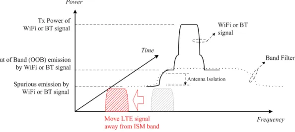
Case 1: Move LTE signal away from ISM band
Figure 1.9: Potential solutions to move LTE signal away from ISM band.
This scenario is illustrated in Fig 1.9. The WiFi transmits data to AP, and LTE receives data from eNB. However, the WiFi signal will leak out to LTE receiver since existing filter restriction. By informing eNB about coexistence interference problem, if the eNB chooses FDM solution to solve IDCI problem, it will move LTE signal away from ISM band. In that way, it can reduce the LTE interference from WiFi signal.
Case 2: Move ISM radio signal away from LTE frequency band
The WiFi transmits data to AP and LTE receives data from eNB, the situation 11
Figure 1.10: Move WiFi radio signal away from LTE frequency band.
can be shown in Fig 1.10. However, the WiFi signal will leak out to LTE receiver since existing filter restriction. By reducing WiFi or BT signal transmission range and making it away from LTE signal, it can reduce the LTE interference from WiFi signal. The WiFi station shall request AP for new operating frequency band. In order to help WiFi radio complete these necessary procedures, LTE also needs to avoid coexistence interference with WiFi radio during the initial stage (e.g. Using LTE denial).
1.3.3
Time Division Multiplexing (TDM)
As shown in Fig 1.11, though the LTE operating band is very close to the WiFi band, there is no interfere since the two radios use orthogonal time resources, e.g., the WiFi transmits signal between t0 and t1 while the LTE receives signal after t1.
DRX based solution for LTE and WiFi
DRX is a discontinuous reception mechanism. When this mechanism is active, it will have a period for LTE to transmit and receive datum , known as the on-duration, and it will also have another period for LTE to not do any action, known as the off-duration (sleep period). In the off-duration, eNB will not allocate any resources to the UE, so the UE can’t uplink data. Besides, eNB will also not downlink data to the UE. The UE
Figure 1.11: Time division multiplexing for coexistence interference avoidance.
will not transmit and receive during off-duration, so it can sleep to save battery power. During the DRX operation, an LTE user can’t send and receive actions in sleep mode. Therefore, in this period, we can use WiFi transmission and reception. Both sides will not be affected by the other side interference. Since the DRX mechanism already exists in current LTE system, using this mechanism to resolve the in-device coexistence interference problem is a good method. It can reduce the opportunity to modify LTE standards and make the operation become more simpler.
When the UE encounters the IDCI problem, it will inform eNB about this situation and require IDC solution. The UE will also provide the eNB with a desired TDM pattern. For example, the parameters related to the TDM pattern may consist of periodicity of the TDM pattern and scheduling period (or unscheduled period). The UE can suggest TDM pattern (e.g. Fig. 1.12). The configuration of scheduling/unscheduled period can
be designed by usage of LTE and WiFi. For example, if WiFi traffic is more frequent than LTE traffic, then the unscheduled period shall be longer than scheduling period. However, this configuration shall also satisfy both radio QoS and throughput constraint. If the unscheduled period is too long, the LTE delay requirement may not be satisfied, and it will result in packet loss.
The final DRX configuration is controlled by eNB (see Fig. 1.13) which can be based on the UE suggested TDM pattern and other possible criteria (e.g. traffic type). The scheduling period corresponds to the active time of DRX operation, while unscheduled period corresponds to the inactive time. The eNB should try to guarantee the un-scheduled period by existing mechanisms, (e.g. appropriate UL/DL scheduling, DRX Command MAC control element usage, and etc). It means that flexibility principles from existing DRX mechanism will be applied (i.e. variable scheduling/unscheduled period is possible) and that no impact on UE HARQ operation is assumed so far. Dur-ing inactive time, UE is allowed to delay the initiation of dedicated schedulDur-ing request and/or RACH procedure.
Figure 1.12: Example of UE suggested TDM pattern.
Introduction of DRX scheme
UE is active during the on-duration while listening to the physical downlink control channel (PDCC) to learn if eNB has data to be transmitted to it. After the activation of the on duration timer, the UE enters Inactive timer. During this timer, UE still listens to the control channel, and the timer will down count with time. The inactive timer will be reset once the eNB has data to transmit. If inactive timer counts to zero, and there
Figure 1.13: Example of DRX configured by eNB to enable TDM.
Figure 1.14: DRX scheme.
is no data buffer in eNB, then UE will enter power saving mode to save power. During this mode, UE can only listen to downlink control message, and it can’t transmit or receive data during this period. Therefore, UE can transmit WiFi signal in this period. In addition to DRX solution pattern, WiFi of UE must use WiFi denial in DRX active time to avoid interfering with LTE. Combining DRX scheme and WiFi denial, WiFi and LTE will not interfere with each other.
1.3.4
Power control (PC)
When there is interference from WiFi uplink, UE can reduce the transmit WiFi power to mitigate the interference to LTE, but it will induce the degradation of WiFi SINR. The WiFi power which UE can adjust must conform with WiFi throughput constraint. To diminish LTE coexistence interference to ISM or GNSS downlink reception, the UE can report the need for power reduction to the eNB. The UE can adjust the power control parameters locally and report the power change value by existing mechanism. How the
report is transmitted (e.g. via RRC or MAC) and what information (e.g. interference type, power reduction value, and etc) should be transmitted to eNB are still not clear for 3GPP. The eNB can adjust the UE transmission power by existing mechanism, e.g. PDCCH or RRC signalling upon eNB receives the report from UE.
This method has two cases:
Case1: LTE power control
In this scenario LTE can reduce transmission power to mitigate interference with WiFi.
Figure 1.15: LTE power control for coexistence interference mitigation.
Case2: ISM power control
In this scenario WiFi can reduce transmission power to mitigate interference with LTE.
1.3.5
Summary for coexistence interference problem solution
Power control
WiFi uplink power reduction will result in WiFi SINR degradation and also lower WiFi UL throughput. If the coexistence interference problem is serious, the WiFi power
Figure 1.16: ISM power control for coexistence interference mitigation.
may need to be reduced by 20dB or even 60dB. Thus, it makes the WiFi throughput very low or even to be zero, and the power control solution becomes unsuitable. It is useful only if IDCI is relatively small.
FDM solution
FDM solution is done by shifting the operating frequency band to degrade inter-ference from one another. However, this method can only degrade interference, it can’t mitigate interference absolutely. When the IDC user is near the cell edge, the remaining interference still can’t be endured by this user, so FDM solution is still not enough to solve IDCI problem sometimes. From another point of view, the operator (e.g. Chunghwa Telecom) may not be able to deploy the overlay coverage over multiple fre-quencies everywhere due to the consideration of deployment cost and coverage planning complexity. UE may not be able to find out an appropriate operating frequency band to use FDM solution because the whole LTE frequency band on operator are interfered by WiFi. It is useful only if IDCI is not relatively large.
TDM solution
By segmenting the time resource for different radio usage, when one radio is on
during a specific period, the other radio should remain silent. This method can totally avoid interference as orthogonal time resources are used. Since the time resources are segmented for different radio usage, the time resources available to the LTE or WiFi radio are reduced. Both LTE and WiFi suffer from throughput loss as the available time slots are limited by the DRX active mode and DRX power saving mode, respectively. We are interested in finding a proper DRX trigger epoch to maximize the total throughput while meeting the individual radio throughput constraints.
The rest of this thesis is organized as follows. In Chapter II, we describe the operat-ing scenarios in which IDCI exists, present the related system model and assumptions. We also show several simulation results to exemplify the serious IDCI problems. In Chapters III and IV, we provide simulation results of SNR estimation and investigate the effectiveness of the DRX-based TDM solution by finding the optimal trigger parame-ters. In Chapters V, we analyze the WiFi and LTE throughput performance via Markov modeling. We investigate the theoretical WiFi throughputs with DRX and without DRX mechanism. Finally, we apply the fairness-aware FD-PF scheduling scheme [15] to simulate the throughput behaviors and study the impacts of the DRX parameters and UE-eNB distance. Our major results are then summarized in Chapters VI.
Chapter 2
System Model, Assumptions and
Problem Formulation
2.1
Scenario and assumptions
A so-called LTE+WiFi offload scenario is considered in the ensuing investigation. We assume that the OFDMA based LTE system operates on LTE band 40 and in TDD mode. The WiFi system complies with the 802.11g standard–an OFDM system operating on the ISM band close to LTE band 40.
How these two networks interact is illustrated in Fig.2.1 where we consider the case where there is only one macrocell base station (BS) and one access point (AP). The LTE system uplinks and downlinks data streams in different (time) subframes (of 1 ms duration) while the WiFi link is active at the same time. By measuring the signal-to-interference-plus-noise ratio (SINR), we shall determine if a DRX-based IDCI solution should be activated.
The following system parameters are needed in subsequent discourse. 1. User mobility:
The user mobility affects the channel’s fading rate which is often classified into fast fading (> 120km/hr) or slow fading (3km/hr, 30km/hr). If the IDCI user moves
fast, the threshold for IDCI decision . 2. LTE and WiFi traffic type:
The traffic types include Http, poisson, FTP, VoIP, or full buffer. 3. LTE and WiFi average SINR:
LTE average SINR is related to the distance between eNB and UE, and it will affect LTE average throughput. WiFi average SINR is related to the distance between AP and UE, and it will affect WiFi transmission rate.
4. Different WiFi stations:
The number of WiFi stations will affect throughput 5. LTE and WiFi operating frequency band:
The interference will be different based on operating frequency band at LTE and WiFi.
6. LTE and WiFi throughput constraint:
The DRX parameters must be chosen to ensure that the LTE/WiFi throughput requirements be satisfied.
2.1.1
A LTE and WiFi coexistence model: Operation and
In-terference
We assume that other WiFi users always have data to transmit and that they always use RTS/CTS mechanism.
We will introduce the procedure of Fig.2.1 and Fig.2.2 as follows. At first, the network will have some data stream to be transmitted to UE. If eNB receives the data stream from network, it will buffer the data stream and start to schedule downlink resources for UE by previous CQI report on DRX active mode, or it will not transmit data when UE operates on power saving mode until the next on-duration timer is activated. UE
Figure 2.1: Interaction between LTE and WiFi models. 21
will decode PDCCH in the downlink subframe to know the position of resource for UE. If UE has WiFi denial, then the LTE downlink subframe will not be interfered by WiFi. However, if UE doesn’t use WiFi denial, then LTE SINR may be interfered by WiFi. WiFi uplink signal will be RTS (request to send) and uplink data, they comply with RTS/CTS CSMA-CA scheme. When channel is idle, UE will count down the backoff timer after DIFS time interval(34us) and transmit RTS signal when the backoff timer becomes zero. And if backoff timer of other users also becomes zero, AP will receive RTS signals from different users at the same time. This situation will cause collision, so the AP will not transmit CTS signal, and channel becomes idle. If users don’t receive CTS, they will extend backoff timer and reselect the random number from the new backoff timer. The IDC user will measure SINR in every subframe and compute the throughput by SINR mapped to modulation coding scheme for each subframe. At last, UE will average the throughput during measured period and decide whether to trigger IDC solution or not.
Referring to Figs. 2.1 and 2.2, we define the following acronyms:
1. RTS+SIFS+CTS+SIFS+Uplink data+SIFS+ACK: It means that WiFi UE will send RTS to AP when backoff timer is equal to zero, and AP will send CTS after SIFS when AP receives RTS. UE will send uplink data after SIFS when UE receives CTS, and AP will send ACK after SIFS when AP receives uplink data. The period of RTS and Uplink data will interfere with LTE radio.
2. Uplink data+SIFS+ACK: If there is no RTS/CTS scheme, UE will send uplink data directly. Moreover, AP will send ACK after SIFS when AP receives uplink data. Only the period of Uplink data will interfere with LTE radio.
3. RTS: If WiFi UE sends RTS to AP, and meanwhile there are other users sending RTS to AP, it will result in collision. Only the period of RTS will interfere with LTE radio.
4. Uplink data: If WiFi UE sends data to AP, and meanwhile there are other users sending RTS to AP, it will result in collision. Only the period of Uplink data will interfere with LTE radio.
5. WiFi Uplink time: If WiFi is transmitting data, it will be one of the cases which are mentioned above( 1, 2, 3 and 4). And red parts of these cases represent the period of WiFi uplink time.
6. TDM solution: For LTE+WiFi case, the TDM solution will be DRX based solution with WiFi denial. Therefore, if the TDM solution is activated, eNB will turn on DRX solution and UE will use WiFi denial to avoid interfering with LTE.
7. FDM solution: eNB will shift LTE central frequency away from ISM band. How-ever, this solution can’t be used for some cases. For example, if eNB only has frequency band which is close to ISM band, the interference will be serious even if the resource blocks are allocated away from ISM band. For another example, because FDM solution can’t avoid interference completely, WiFi interference will still cause serious effect for UE which is located at cell edge.
8. Power control solution: If LTE is interfered by WiFi, WiFi will decrease transmis-sion power for diminishing the interference to LTE and vice versa. If WiFi lowers its uplink power for PC solution, WiFi may also decrease the link performance between AP and UE, which will result in increasing the WiFi transmission time. It is only used in the case that interference is light because of the limit of maximum power reduction.
9. For DRX in the power saving mode, it has inactivity timer which can extend LTE transmission time. During this inactivity timer, if UE receives the paging signal from PDCCH, UE will reset this inactivity timer and receive the data.
the period of WiFi uplink time during the DL subframe at present. We need to calculate the period of WiFi interference per subframe to know the WiFi activity property.
11. If the IDC user collides with other users, AP will receive RTS or Uplink data from IDC user and other signal from other users. AP will detect whether collision occurs. If so, it will not transmit CTS or ACK to the IDC user. If the IDC user doesn’t receive response from AP after DIFS(DCF inter frame spacing), IDC user will double its backoff timer and contend with other users again.
12. We can use LTE and WiFi traffic to decide the DRX active ratio. Ex. DRX active ratio=active time/DRX cycle=LTE traffic/( LTE+WiFi traffic)
13. When user operates for on-duration timer or Inactivity timer of DRX scheme, it can still receive DL data from eNB, and eNB will allocate the DL resource around the central frequency by previous CQI in downlink subframe.
14. We can calculate SINR by interference time from (10). If interference time is long, the LTE DL subframe will be interfered by WiFi with large probability.
2.2
Problem formulation
2.2.1
A typical IDCI avoidance procedure
Referring to Fig 2.3, we describe an IDCI-avoidance procedure in the following.
1. First, UE will discover the in-device coexistence problem, and it will try to solve it by itself. If the interference becomes too serious for UE to handle this problem, it will need assistance from eNB to deal with the IDCI problem.
Figure 2.3: A typical IDCI avoidance procedure.
2. After UE wants to trigger IDCI solution and demands eNB for a IDCI solution, UE will send trigger indication to eNB, and this trigger indication will include some suggestible IDCI information to eNB (e.g. power control: the value of max-imum power reduction; TDM solution: WiFi uplink activity ratio; FDM solution: usable/unusable carrier frequencies)
3. After eNB receives the indication of IDCI, it will decide an appropriate solution according to different situations (e.g., if usable frequencies are not existed or they are overloding, then eNB will use TDM solution for UE). Finally, eNB configure a specific solution for UE.
4. UE will receive IDC configuration demand and process the IDC solution given by eNB. (e.g. For TDM solution: eNB will configure an appropriate DRX parameters. For FDM solution: eNB will tell UE which frequency band should be used latter) During the IDCI avoidance procedure, the UE must be denied until this IDC proce-dure is ended. Otherwise, WiFi will interfere with LTE reception for IDC information
and induce the IDCI procedure failed.
2.2.2
Motivation for IDCI solution trigger study
The in-device interference refers mainly to the adjacent channel interference between WiFi and LTE band 40. If UE can not solve the IDCI problem by itself, it should inform its serving eNB the related IDCI information so that the eNB can determine if an IDCI solution should be activated, i.e., the purpose of IDCI information reporting is to trigger an IDCI solution from the serving eNB. However, TDM solution has drawback mentioned in Section 1.3 because the available transmission time is limited by DRX active mode and DRX power saving mode for LTE and WiFi respectively. Both LTE and WiFi suffer from performance loss. If we activate DRX too early (e.g. sending a trigger message whenever the ISM radio is active), both LTE and WiFi throughput will degrade as a result of DRX-induced transmission time reduction. On the other hand, if we activate DRX too late, LTE DL signal will be severely interfered and cause significant throughput loss. Hence finding an appropriate trigger time is a major design concern.
Chapter 3
Simulation Based TDM
Solution–Operation Assumptions
3.1
WiFi operation assumptions
3.1.1
CSMA/CA with RTS/CTS transmission scheme
The IEEE 802.11g standard uses a CSMA/CA (Carrier Sense Multiple Access/Collision Avoidance) protocol for network access and collision avoidance.
I The steps for 802.11 CSMA as follows:
Step 1: When a station has data to transmit, it will sense the channel. If the channel is idle, the station is allowed to transmit data.
Step 2: When a station is operating at busy mode, the station should wait for transmit until the channel becomes idle.
I The scheme for CA as follows:
To make sure the basic data frame unit will not be interrupted by other data frames, it use different Inter-Frame Space (IFS) types (e.g. SIFS, PIFS and DIFS). If the IFS is shorter, then the priority will be higher. SIFS is short inter-frame space, it is used for
immediate acknowledge message. PIFS is PCF (Point Coordination Function) IFS, it is used for stations wait the PIFS to transmit data at contention free mode when channel becomes idle, and it is also the WiFi beacon waiting time at DCF scheme. DIFS is DCF (Distributed Coordination Function) IFS, it is used for stations wait the DIFS to transmit data at contention free mode when channel becomes idle. The IFS relationship will be SIFS(16us) < PIFS(25us) < DIFS(34us).
To minimize the probability of collision when the number of users increases, the IEEE 802.11 standard uses binary exponential backoff algorithm to solve this problem.
Figure 3.1: DCF with the CSMA/CA protocol.
As can be seen from Fig. 3.1, the contention window size for backoff timer will grow twice every time when collision occurs until it reaches the maximum window size. UE will transmit data after the backoff timer count down to zero and the contention window will be reset to the minimal contention window size if the transmission was successful.
As shown in Fig. 3.2, it can be regarded as a data frame from Fig. 3.1. At this scheme, a UE will transmit RTS (request to send) signal first to avoid contention ,and the target AP will send CTS to the UE after it receives RTS successfully. Next, the UE will transmit data frame and expect to receive the ACK from the AP to finish this data frame transmission. If the packet size greater or equal to 2312 bytes, the RTS threshold, then WiFi will use RTS/CTS transmission scheme.
Figure 3.2: Data frame for the RTS/CTS scheme.
Figure 3.4: TDD frame structure.
3.1.2
Relationship between the number of WiFi users and IDC
user
We assume that other WiFi users operate in saturation condition, it means that they always have packet to transmit. We show that how other WiFi users will compete the channel with the IDC WiFi user using CSMA/CA scheme in Fig. 3.3. If the IDC user senses channel to be busy before the backoff timer goes to zero, then it can’t transmit WiFi data until the channel becomes idle again and the LTE will not be interfered by WiFi during this period. On the other hand, if the IDC user contend the WiFi channel successfully, then the IDC user’s WiFi will transmit data to WiFi AP and thus interferes the LTE DL receiving data.
3.2
LTE frame structure and operation assumptions
Fig. 3.4 presents a TDD frame structure, and one radio frame is 10ms which is composed of ten subframes with the length of 1ms. This scheme needs Guard period when it switches from the downlink to the uplink due to random access synchronous.
As shown in Fig. 3.5, we show the TDD configuration type for 3GPP. Since the downlink traffic usually has larger loading than the uplink one for a UE. The number of
Figure 3.5: TDD configuration.
downlink subframe should be more than the number of uplink subframe. Here, we set the TDD Uplink-downlink configuration to be 4, where the number of uplink subframe, the number of downlink subframe ,and the number of switch subframe are 2, 7 and 1 respectively.
As can be seen from Fig. 3.6, the resource block can be composed by many downlink resource grid. A grid is called a resource element, and it is a basic unit which distributes over a resource block. Each grid bandwidth contains one subcarrier (15KHz), and its length is one- symbol period (71.4us). Each subcarrier is orthogonal to each other (see Fig. 3.7). A resource block has 12 subcarriers and 7 OFDM symbols, so it includes 84 resource elements. With the knowledge of how many resource blocks is assigned to the UE by the eNB along with the SINR in this subframe, we can calculate the throughput by MCS (Modulation Coding Scheme) level and CQI (Channel quality indicator) table latter.
3.3
LTE downlink SINR
The power spectrum density of thermal noise is -174(dBm/Hz) and if we consider only the inter-cell interference, the average power spectrum density for interference plus noise level will be -164(dBm/Hz) in the cell edge for the rule of thumb. It this work, we assume that an IDC user is located on the urban microcell scenario where the coverage region
Figure 3.6: LTE Resource Block (RB) structure.
Figure 3.7: OFDM subcarrier spacing.
of the base station is 500 meter. We also assume that the distance between the UE and the eNB is 425 meter which is close to the cell edge. We adopt the pathloss model in 3GPP 25.883, follow the function pathloss(dB) = 34.53+38*log10(the distance between
the UE and the eNB). In this case the pathloss will be 134.41(dB). The eNB transmis-sion power is set to be 46dBm and the system bandwidth is 20MHz. The bandwidth for the data transmission will be 18MHz which is smaller than the system bandwidth be-cause it requires a guard band to prevent the adjacent channel interference. As a result, the average power spectrum density is 46(dBm)-10*log10(18MHz)= -26.553(dBm/Hz)
and the average SINR calculation considering three informations which are power spec-trum density of signal, pathloss and power specspec-trum density of interference plus noise level. Through the calculation, -26.553(dBm/Hz)-134.41(dB)-(-164(dBm/Hz)), the av-erage SINR is thus to be 3(dB).
In order to investigate SINR performance under IDC interference, we assume that the center frequency for LTE and WiFi are 2370MHz and 2412MHz,respectively. The interference level is -107dBm/Hz. The denominator of SINR is composed of noise power, inter-cell power and in-device interference power. The average power spectrum density of interference will be 10*log10(10
−164(dBm/Hz)
10 + 10
−107(dBm/Hz)
10 ) , which is approximate to
-107(dBm/Hz), the power spectrum density of tansmission signal, pathloss and the in-terference is -26.553(dBm/Hz),-134.41(dB) and -107(dBm/Hz), respectively, the average SINR with IDC interference is -53.96(dB) in this case. Hence, if the in-device interfer-ence occurs then SINR will be degrade dramatically and the UE can’t get any correct information from the eNB.
3.4
LTE downlink throughput
After a UE measures SINR, the UE will report CQI to the eNB and the eNB will choose a modulation coding scheme according to the CQI reported from UE. SINR will be calculated by the eNB using the above mentioned method and the eNB will
Figure 3.8: SINR versus BLER with different MCS level.
use Fig. 3.8 to find out a proper MCS (modulation coding scheme) level and BLER. In general cases, the block error rate will not be larger than 0.1, so if we want to select a MCS level to maximize the transmission rate, then we should select maximum MCS level with the constraint that BLER is smaller than 0.1. As can be seen from Fig. 3.9, different MCS level will represent different efficiency, and the efficiency is defined by how many bits can a resource element provided. The eNB will allocate some resource blocks to the UE which uses the same MCS level. We assume that the UE will take 10 RBs during a subframe interval, and thus the resource elements that each UE can obtain is 10*12(subcarriers)*7(symbols). So, the transmission bits for the UE will be 10*84*efficiency during a subframe. The efficiency will be different for different subframes and we can obtain the average throughput by averaging over different subframes.
Chapter 4
Appropriate Occasion To Trigger
TDM Solution
It is clear that [4] the decision to trigger an IDCI solution depends on the WiFi interference level and the WiFi UL activity (see Fig. 4.1).
Figure 4.1: IDC indication for LTE DL.
4.1
The effect of WiFi/LTE parameters and WiFi/LTE
throughput
1. WiFi interference level:
(a) WiFi/LTE transmission power (b) WiFi/LTE operation frequency band 2. WiFi UL activity:
(a) Number of WiFi users
(b) WiFi traffic type (Full buffer, FTP, http,. . .) (c) WiFi UL transmission rate
(d) WiFi UL buffer 3. LTE DL activity:
(a) LTE traffic type (Full buffer, FTP, http,. . .) (b) LTE DL transmission rate
(c) LTE TDD configuration (d) LTE DL buffer
4. DRX parameter:
(a) LTE active time/DRX cycle = DRX activity ratio
How do these parameters affect performance(throughput) is the issue we will discuss as follows:
Figure 4.2: Number os WiFi users versus Normalized throughput ratio.
Parameter value WiFi power from UE 20dBm LTE power from eNB 46dBm LTE center frequency 2370MHz WiFi center frequency 2412MHz WiFi interference power per Hz -107dBm/Hz
Number of RBs for IDC UE 10RBs WiFi transmission rate 6Mbps
Number of WiFi users 2 DRX parameter 80/128 (active time/DRX cycle)
LTE traffic type Full buffer WiFi traffic type Full buffer Distance between UE and eNB 420m
Average SINR no IDCI 3dB
Channel Model SCM (Spatial Channel model) from 3GPP 25.996[5] Table 4.1: Simulation assumption for LTE and WiFi parameters.
Number of WiFi user
Figure 4.3: Number of WiFi users and WiFi UL activity..
As shown in Fig. 4.2, these throughputs are normalized by the throughput without interference. What we mean by no interference implies that both LTE and WiFi operate independently without interfering to each other. The case “without DRX” means LTE and WiFi interfere with each other and both ignore the IDC interference. The case “with DRX” means that UE triggers an IDC solution as soon as WiFi is on and LTE and WiFi will operate on DRX on-duration and off-duration, respectively. We assume that LTE and WiFi are full buffered, i.e., they always have data to transmit. As shown in Fig. 4.2, we find that if the number of WiFi users increases, then LTE DL throughput will increase because the probability of WiFi contention will increase and the WiFi UL ratio will thus decrease. As a result, triggering DRX is not guaranteed to be the best policy with respect to the LTE DL throughput.
From Fig. 4.3, we conclude that WiFi UL activity is influenced by the number of WiFi users, and it is inverse proportional. To explore the number of WiFi users, we can use collision probability of RTS. Before WiFi transmits data, it needs to transmit RTS(request to send) information to AP. In consequence, UE can calculate the collision probability of RTS to analogize the number of WiFi users. In other words, inverse of collision probability of RTS is equal to the number of WiFi users approximately. In Fig. 4.4, we assume that the number of WiFi users is two. Because there are always data in WiFi UL buffer to be transmitted, WiFi UL ratio is still high in no DRX case even if WiFi transmission rate increases.
Fig. 4.5 shows that WiFi UL ratio degrade linearly when WiFi data increases. When WiFi transmission rate increases, the transmission time for one packet will decrease. Because the WiFi contention window size will not change with the transmission rate, it means that WiFi idle time increases when WiFi transmission rate increases. So, the WiFi UL ratio will decrease when WiFi data increases.
In our simulation, we assume that WiFi receives ACK from the AP, with a possibility colliding with LTE UL ACK which results in the reduced probability of the success WiFi
Figure 4.5: WiFi transmission rate versus WiFi UL ratio (Full buffer case)
uplink transmission. Therefore, for the WiFi UL ratio, the performance of the no-DRX case is worse than that of the no-interference case. From the simulation results of Fig. 4.6, we assume that the number of WiFi users is two. Because there are always data in WiFi UL buffer to be transmitted, WiFi UL ratio is still high at no DRX case.
Fig. 4.7 shows that when WiFi transmission rate is large enough, the WiFi activity ratio will degrade fast because the WiFi buffer will be empty sometimes. Compared to no interference and no DRX cases, since no DRX case needs higher data rate to empty the WiFi buffer, WiFi UL ratio will be larger than no interference case.
The results presented in Figs. 4.6 and 4.8 tell us that when WiFi traffic becomes lighter, WiFi throughput will saturate at 5.5 Mbps, which means that WiFi activity ratio for these WiFi transmission rates will become smaller. LTE DL throughput ,no DRX case will increase faster than LTE DL throughput, with DRX case ,because it has more time resources can be used as successful transmission. The WiFi UL ratio with DRX is close to WiFi UL ratio with no interference when WiFi transmission rate is large enough because WiFi traffic is so light; see Fig. 4.9. In this case, even if WiFi only can
Figure 4.6: WiFi transmission rate versus WiFi/LTE throughput (traffic 11Mbps)
Figure 4.7: WiFi transmission rate and WiFi UL ratio (traffic 11Mbps)
Figure 4.8: WiFi transmission rate versus WiFi/LTE throughput (traffic 5.5Mbps)
transmit data at DRX sleep mode, it is enough to empty the WiFi UL buffer.
WiFi traffic type
The characteristic of different traffic types will affect IDC trigger decision. The traffic load can be light or heavy, and the traffic type can be burst or constant. If WiFi traffic is light, it doesn’t need to trigger IDC . Instead, we can use WiFi denial to wait until LTE finishes receiving data. If WiFi traffic is heavy, WiFi UL buffer will have queued data for a long time. It needs to consider whether to activate DRX solution to get a better performance. If WiFi traffic is heavy and burst, the DRX cycle can be chosen to match the burst data inter-arrival time.
WiFi UL buffer
UE can predict how much time it needs to take at least to empty the WiFi UL buffer by the WiFi transmission rate and the number of WiFi users. It is also an important information to decide whether to trigger IDC or not. It may be better not to trigger IDC solution in the case for WiFi buffer remaining small volume data and traffic type being burst traffic, even if WiFi interference power is very high. Because the WiFi buffer is going to being cleared to empty, UE can predict that WiFi will not uplink data after WiFi uplink buffer is empty and LTE can receive data without WiFi interference.
LTE DL activity
If LTE downlink activity ratio is small, maybe we can just use WiFi denial to solve IDC problem.
DRX parameter
In the simulation assumptions, we don’t consider DRX with inactivity timer because if LTE always has data needed to be received, then the inactivity timer will extend and thus WiFi has no chance to transmit with DRX power saving mode.
Assuming that the number of WiFi users is two, Fig. 4.10 plots the normalized LTE/WiFi throughput performance. If we increase on-duration timer, LTE DL through-put will increase, but WiFi UL throughthrough-put will decrease. If we increase DRX cycle with