A framework for facilitating multi-dimensional information integration, management
and visualization in engineering projects
I-Chen Wu
a, Shang-Hsien Hsieh
b,⁎
,1 aDepartment of Civil Engineering, National Kaohsiung University of Applied Sciences, Kaohsiung, Taiwan
bDepartment of Civil Engineering, National Taiwan University, Taipei, Taiwan
a b s t r a c t
a r t i c l e i n f o
Article history:
Accepted 12 December 2011 Available online 20 February 2012 Keywords: Project management nD 4D Information integration Information visualization
This research proposes an application framework, named PIIM Framework (Project Information Integration Management Framework), to effectively solve the problems of integrating project information and system inter-faces among different participating parties and engineering application systems, as well as to providefive kernel modules to encapsulate complicated management and visualization functions. The PIIM Framework is con-structed on the basis of object-oriented techniques, such that users can take advantage of object oriented pro-gramming to easily develop applications required. In addition, this research conducted an actual engineering project example, and developed a prototype system based on the PIIM Framework to verify its feasibility. Through the feasibility study, it has been demonstrated that the PIIM Framework can provide not only provide a more efficient method to integrate, manage and visualize project information, but can also save programming time for the project management team when developing a project management system from scratch.
© 2011 Elsevier B.V. All rights reserved.
1. Introduction
Today's construction projects are becoming ever more complex and time driven, especially as the amount of project data and active project participants increases. Several known issues pertaining to this phenomenon are described as follows. Firstly, the construction industry continually seeks to apply new information technology (IT) based methods to substitute the traditional paper-based manage-ment methods, with the need for information to be created just once and used over the entire project lifecycle, rather than the gener-ation of the same informgener-ation multiple times in current processes. However, the diverse range of project participants still wish to main-tain their own data, structured to suit their own specialized needs. Hence, the differences of data definition, data format, and data stor-age increase the difficulty of integrating the data from diverse sources in engineering projects. Secondly, current information management methods are based on file collection approaches, which have no relationship with each other. Therefore, project managers cannot sider engineering information synthetically in performing project con-trol. If they desire increased accuracy and total control of engineering projects, project managers must spend time collecting and handling data which are generated from different systems. Thirdly, although much of this engineering information is produced electronically and is visual in nature, teams primarily use paper-based views of engineering information to share information with one another in project meetings.
The project participants would not be able to understand the project status comprehensively due to the lack of an intuitive and user-friendly visualization tool to display the related project information. Fourthly, the participants in the project need to communicate and transfer information with each other, either within a phase or between two phases. However, information exchange between project parties is limited to the digitalfiles, a medium in which retrieval and exchange is inconvenient and inefficient.
In addressing the abovementioned issues, the project ment system has become increasingly important in a project manage-ment effort. The role of the project managemanage-ment system is to provide assistance to the project management team in handling complicated project information, and providing useful and significant information for controlling the project and supporting decision-making. At pre-sent, the project management systems which are employed in the construction industry can be divided into two types. Thefirst type is commercial software, in which projects are managed using mostly Gantt Charts, Program Evaluation and Review Technique (PERT)
[1–3]and Critical Path Method (CPM)[4]. These management tech-niques have spread quickly into many private enterprises and repre-sent significant commercial value. Thus, much of the related software and modules have been developed by commercial software compa-nies, for example, Microsoft Project, Oracle's Primavera P6 Profession-al Project Management, Daptiv Project Portfolio Management (PPM) and Project Management Module in SAP's ERP solution. The second type of project management systems is in-house software, which is usually utilized where the commercial software does not offer suf-ficient or special functionalities for use in particular engineering projects orfirms. Therefore, some firms will develop the in-house
⁎ Corresponding author. Tel.: +886 7 381 4526x5238; fax: +886 7 383 1371. E-mail addresses:[email protected](I.-C. Wu),[email protected](S.-H. Hsieh).
1Tel.: + 886 2 3366 4313; fax: + 886 2 2368 8213.
0926-5805/$– see front matter © 2011 Elsevier B.V. All rights reserved. doi:10.1016/j.autcon.2011.12.010
Contents lists available atSciVerse ScienceDirect
Automation in Construction
j o u r n a l h o m e p a g e : w w w . e l s e v i e r . c o m / l o c a t e / a u t c o nsoftware to meet their needs. Examples of this include Bechtel[5], Parsons Brinckerhoff[6,7], Kajima[8,9], CECI, CTCI[10,11], RUEN-TEX, SINOTECH among many others.
While the abovementioned systems can assist project manager in managing the engineering project, they still leave significant issues unresolved. This may be considered as two issues: (1) Traditional project management systems mainly provide text, graph and compli-cated network schedules for controlling project and making deci-sions. Today's complex and time-driven projects, coupled with increasingly large project information volumes and active project participants, require more effective integration, management and communication tools than that which traditional project manage-ment systems can provide. Because of the complexity of the con-struction industry, the multiple phases of the concon-struction project life-cycle combined with project participants using various heteroge-neous systems causes information integration to be an important and imperative step in achieving efficient and effective collaboration for the project's success. For example, the construction project team can understand the conflicts in relation to time and space in advance by using the conflict detection mechanism, where the computer in-forms team members of parts of the building which are in conflict or will clash, by the integrating schedule information and 3D model. In addition, this allows quality control to occur at any time and at any place during the engineering project. The aim of quality control is to oversee for the completion of the engineering project in a timely manner through the most profitable and cost-effective way. These questions arise in relation to multi-dimensional information inte-gration, management, and visualization of engineering projects. It follows from what has been discussed above that an effective pro-ject management system should provide not only provide sufficient and comprehensive information to facilitate project management, but also the various visualization tools to assist with information distribution and communication; (2) In the construction industry, the contents of project management will be changed to meet special engineering requirements and contract stipulations in every pro-ject. Even though commercial project management systems can provide the most commonly required functions, they often do not have enoughflexibility to change management workflows or en-hance certain functionalities when required. On the other hand, some construction management firms develop in-house project management system for fulfilling specific project requirements, at an immense cost of time and money on development and mainte-nance efforts.
In this research, we propose a Project Information Integration Management Framework (PIIIM Framework) to address the afore-mentioned issues. The PIIM Framework is a reusable and semi-complete application that can be customized to deliver specific appli-cations. We hope that future developers will be able to efficiently develop a useful system for construction project management on the basis of the PIIM Framework. We also develop the prototype Visual Project Management Information System (VisPMIS), based on the proposed PIIM Framework, to assist project management teams in resolving the issues of integration, management and visualization of construction project information. Through this example applica-tion, the PIIM Framework proposed in this research is demonstrated and the functionality is verified.
2. Related works
In this section, we briefly review the main literature related to our work, with the purpose of highlighting our contributions in this research area. Construction project management is responsible for the application of modern management techniques and systems to the execution of a project from start tofinish and to achieve predeter-mined objectives of scope, quality, time and cost to the equal satisfac-tion of those involved. However, development is required on various
related topics under the following focus areas: (1) Because of the complexity of the construction industry, the multiple phases of the construction project life-cycle, and the project participants using var-ious heterogeneous systems, information integration becomes an important and imperative step to achieve efficient and effective col-laboration for project success; (2) The use of visualization to present engineering information is an effective and efficient method for the distribution of information and communication with project partici-pants during project meetings. A detailed discussion is presented in the next section.
2.1. Multi-dimensional information integration
During the life cycle of an engineering project, a voluminous amount of data and information is usually created along the delivery processes of construction products. The construction project team must consider a wide variety of information when controlling the project and making project decisions. In general, teams primarily use paper-based views of project information and share information throughfiles. Because the information defined in the information dis-tribution systems of various parties are usually different, they are always difficult to integrate with one another for the purpose of infor-mation communication and distribution. Important relationships be-tween different pieces of project information are not communicated effectively as construction information is not effectively integrated and used. At present, some data models have been established for in-tegration purposes. The Building Information Model (BIM)[12]is a computer model database of building design information, which may also contain information about the building's construction, man-agement, operations and maintenance. Some research examples in-clude Azhar et al., who demonstrated the use of BIM for sustainable design and the LEED® certification process[13], and Hu et al., who applied BIM technology to address conflicts and structural safety problems during construction[14,15]. However, as these solutions are based on different and incompatible standards, an open and neu-tral data format is required to ensure data compatibility across the different applications (e.g. Autodesk Revit, Bentley TriForma, Graphi-soft ArchiCAD and so on). Industry Foundation Classes[16], devel-oped by the International Alliance for Interoperability, can provide such integration and interoperability capabilities. The IFC data model is an object-oriented data model based on class definitions representing the items (elements, processes, shapes, and so on) that are used by software applications during a construction or facility management project. Implementations of IFC have been reported in various construction IT system integration projects [17–20]. In addition, Salford University proposed the concept of nD Modeling, en-abling multidimensional information integration, which it foresees as essential in the future of construction management[21,22]. Although IFC can fulfill the goals of data sharing and information integration, it still falls short of providing the related objects and processes for pro-ject management. The current research attempts to integrate multi-dimensional information into the database through programming, or provide related project data on 3D models using CAD software API. This approach, relying on proprietary software, is difficult to reuse without the particular software, and is constrained byfixed development methods. In this research, we provide a moreflexible and simple mechanism to handle the multi-dimensional information integration. Firstly, we design and develop the integrated data model to describe and store all the project information. Therefore, the inte-grated data model can be used to demonstrate the entire construction lifecycle including project management, the processes of construc-tion, and facility operation. Following this, we provide not only a spe-cial module that contains a number of importing functions to address the existing project information into the integrated data model, but also provide a management module to access the integrated data model including functions such as data creation, data query, data
deletion, data insertion, data update, and so on. Users will be able to employ our modules and the integrated data model to build their ap-plication to address the multi-dimensional information integration without any commercial software.
2.2. Visualization for communication and information distribution Treicher[23], an experimental psychologist, conducted a famous psychological experiment to determine how human beings obtain in-formation. Through a large number of experiments, he proved that 83% of the information received by human beings is by the sense of sight, and the remainder is by the senses of hearing, smell, touch and taste, supporting the view that information visualization is the most essential for communication and information distribution.
Liston et al.[24,25]studied the problem of communication in en-gineering workspaces, which could be variably defined as physical or virtual spaces where people work, share and use information. From observations of numerous design and construction review meetings, they discovered that teams spent most of their time on descriptive, explanative, evaluative and predictive tasks. All these tasks are critical to enabling better decision-making by project managers. In this re-search, we employed the aforementioned four tasks to analyze the current information distribution system in construction projects to determine whether sufficient information was being provided. The information distribution system may be classified into four types according to their characteristic of information visualization. The first type is the 1D system, which conveys information through text, attributes and tables. Examples of these include project websites, da-tabases and general management information systems. Such systems record and describe the project information in detail. The second type is the 2D system, which presents information mainly in the forms of graphs, charts or maps, such as output from GIS, ERP, 2D CAD, and so on. These systems assist the project manager in explaining project decisions, the rationale of the project schedule, and also support them in evaluating project goals and ensuring that project requirements are met. The third type is the 3D system which uses 3D models to pre-sent the actual project status and analyze space conflicts, with exam-ples including 3D CAD and virtual reality systems. These applications harness 3D visualization to assist descriptions of engineering project status, and enhance communication and discussions during project meetings. The fourth type is the 4D system which binds 3D models with their corresponding construction schedules in their simplest forms. This has recently emerged as a method of providing engineers with an effective tool for managing the complexity of coordination as well as conflicts before the actual commencement of construction. Some examples include 4D CAD and construction simulation systems. The realization of 4D CAD technology has also been greatly accelerat-ed by the availability of powerful commercial 4D CAD tools, such as Bentley's Navigator, Intergraph's SmartPlant Review, BALFOUR's FourDscape, Common Point's Project 4D and ConstructSim [26]. There have been numerous, albeit similar, research studies into the use of 4D systems. The important detailed study by Stanford Univer-sity was instrumental in initiating interest in this area[27–29]. Chau et al. built a 4D-GCPSU for construction management[30,31]. Hsieh et al. developed a Construction Director, a 4D simulation system for plant construction[10,11]. Huang et al. developed a virtual prototyp-ing system for simulatprototyp-ing construction processes[32]. Dawood and Sikka[33]provided quantitative evidence that a 4D model can in-crease the efficiency of communication along with the interpretive ability of a construction project team. Even though 4D technology can increase the ability of project managers in providing better man-agement and visualization in construction project manman-agement, there is room for further development in providing sufficient information for uncovering problems and making better decisions.Table 1 sum-marizes the different task emphases and possible outcomes of the four information visualization systems that have been described.
Based onTable 1, we are of the view that an efficient information distribution system ought to support all four kinds of characteristics of information visualization at the same time. Therefore, this research proposes a new concept of information visualization, named the 4D+
Multi-Data-View, to present the integrated data of engineering pro-jects, with advances towards providing significant useful information for use in project management and decision-making. The meaning of “4D+” is to provide the additional characteristics of information
visu-alization on top of the base 4D information visuvisu-alization. Hence, users will be able to view the text which describes the project information, the graph to view the project statistics and progress, the 3D models to present the building status and the 4D models to display the construction simulation in the same view. Furthermore, the “Multi-Data-View” implies that users will be able to query and view the inte-grated data with the different views according to their requirements as shown inFig. 1. In this approach, users will be able tofind the nec-essary and relevant data they need in a more direct and accessible way. This research developed a visualization and management mod-ule to realize this concept. The management modmod-ule provides func-tions to acquire the required data the user needs, and passes it on to the visualization module to display the results in different ways according to the user's requirements.
3. PIIM Framework 3.1. Overview
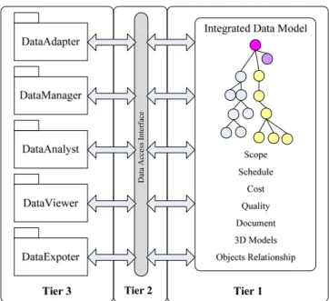
As shown inFig. 2, the PIIM Framework is an application frame-work which can be divided into three tiers. Thefirst tier is the inte-grated data model, which describes and stores information about entire engineering projects; the second tier is the data access inter-face, which mainly deals with data access between the integrated data model and kernel module; and the third tier is the kernel mod-ule, which provides core project management services and encapsu-lates complicated project management functions intofive easy-to-use modules: DataAdapter, DataManager, DataAnalyst, DataViewer and DataExporter.
3.2. Integrated data model
This research proposes an integration data model which can be used not only for storing engineering information, but also providing internal system data in the PIIM Framework. As shown inFig. 3, the integrated data model can be broken down into three parts. The first part is the IFC Data Model, which is employed to describe most of objects in engineering project management, for example, 3D ob-jects, schedule obob-jects, cost objects and document objects. The second part is the User-Defined Data Model, which works with the IFC Data Model to extend its insufficient management objects, such as quality statistics objects and scope objects. The third part is made up of Rela-tionship Objects which define the relationship between IFC objects and User-Defined objects. Both User-Defined Data Model and Rela-tionship objects are described by XML.
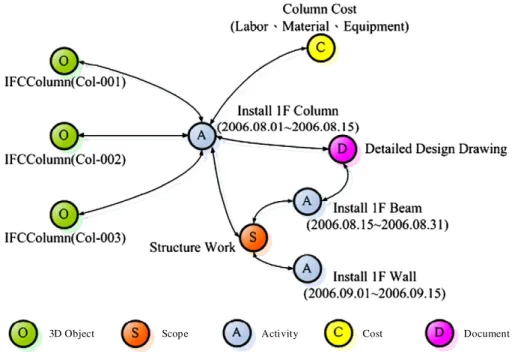
This integrated data model has the important characteristic of the multi-directional data link, as shown inFig. 4. The“Scope” item is parent to a lot of“Activity” items and “Activity” item is related to many other items, which can be“3D Object” items, “Cost” items,
Table 1
Characteristics of different information visualization.
1D system 2D system 3D system 4D system Descriptive ●
Explanative ● ● ●
Evaluative ● ● ●
“Document” items, and so on. Each of the items records the “related” and“relating” relationship. Thus, users will be able to easily find the related items through these multi-directional links. For example, a designer would be able to understand the related cost and schedule information through linking from the relevant“3D object” items; a planner would be able to view the related 3D model by linking from the relevant“Scope”, “Cost” and “Schedule” items.
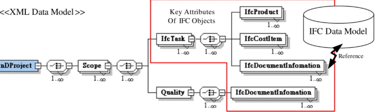
AsFig. 5shows, we adopt the XML technique to organize and con-struct the integrated data model. The XML con-structure can describe the User-Defined Data Model and Relationship Objects, as well as saving the key attribute of IFC Objects for use as a link for matching and obtaining the data from the IFC Data Model.
Establishing the integrated data model provides four benefits: (1) it can be used for storing the information of the entire project; (2) it can be employed to decrease errors made. For example, the struction project team will be able to understand in advance the con-flicts in terms of time and space by using the conflict detection mechanism where the computer informs team members about parts
of the building in conflict; (3) it can be utilized to provide significant information for project management and decision-making. For exam-ple, a construction project team could conduct the Earned-Value anal-ysis method, which includes schedule and cost data for analyzing and reviewing the relationship between schedules and cost overall; (4) users will be able tofind the data they need efficiently and effec-tively through the relationships of multi-directional links.
3.3. Data access interface
The data access interface will increase the ease of posing basic queries and update requests to the integrated data model to which it is connected, regardless of the native language of the integrated data model. It will also allow access to the integrated data model in their native language for more complex requests. As mentioned above, the integrated data model is established on both the IFC Data Model and the XML Data Model. Thus, the PIIM Framework involves two types of data access interface, one being the IFC data access inter-face and the other being the XML data access interinter-face.
In this research, the IFCsvr ActiveX Component [34], an open source library for handling IFC data, is employed. It includes features such as a dictionary of IFC schema information and functionality for representing and manipulating instances of IFC objects. Furthermore, we developed the XML data access interface using Microsoft products and technologies. The System.Xml namespace provides standards-based support for processing XML, which is available in the .NET Framework.
3.4. Five kernel modules
The PIIM Framework allows for the segmenting of complex items into manageable modules according to the particular purpose, and encapsulates complex implementation details behind a stable inter-face. The modules of PIIM Framework are similar to Lego pieces which can be assembled in many ways to suit different purposes. This approach enables applications to be built quickly, and saves development effort. A more detailed discussion follows.
3.4.1. DataAdapter
DataAdapter provides functions for receiving and transforming the common data formats encountered in construction into the PIIM Framework. DataAdapter can support approximately 80% of the data
3D object Cost Item
Schedule Item
Quality Item Document Item
3D object Schedule Item
Cost Item Quality Item
Data Model
Data Model
Cost View
ScheduleView
Scheduler
Accountant
Document ItemFig. 1. The concept of“Multi-Data-View”.
formats generated from commercial software packages. This module provides three functional classes. The first is C3dObjectAdapter, which assists the program to import 3D models created using any commercial CAD software (for example, ArchiCAD, Triforma, and Revit). The second is CScheduleAdapter, which is capable of import-ing Project XML data which is generated from MS Project or Prima-vera P3, and then transforming it into the IFC 2 × 3 data format which is employed in the integrated data model for integration. The third is CCostAdapter, which can adapt and manipulate the Microsoft Office Excel data format for cost data integration.
3.4.2. DataManager
DataManager is responsible for data management and manipulation. The main functions are divided into four parts, as follows: (a) Objects Management: the DataManager includes many different classes which enables the provision of functions for manipulating objects, such as create, modify, delete and query; (b) Data Structure: the DataManager defines some data structure for use in the PIIM Framework, such as class CPiimTreeNode for viewing multi-dimensional information; (c) Simulation Table: the class CSimulationTable can provide functions for collecting and storing the required data for simulating construction processes, which can decrease data handling time; (d) Others: the Data-Manager will provide functions for assisting the internal operations
within the PIIM Framework, such as opening and saving the PIIM Project which includes the integrated data and the related views and graphs.
3.4.3. DataAnalyst
This research employs the Earned-Value analysis method[35–37], which is a project management technique used for measuring the project progress in an objective manner, and for controlling and mon-itoring the construction project. The EVM function in the VisPMIS combines measurements of schedule performance (i.e., behind/ ahead of schedule) and cost performance (i.e., under/over budget) within a single integrated window. When properly applied, EVM can provide an early warning of performance problems and commu-nicate this to all stakeholders. After the integrated data model is established, the class CCalEarnedValue of DataAnalyst can provide the calculation functions of Earned Value analysis, including for example, Budgeted Cost of Work Schedule (BCWS), Budgeted Cost of Work Performed (BCWP), Actual Cost of Work Performed (ACWP), Schedule Variance (SV), Cost Variance (CV), Cost Performance Index (CPI) and Schedule Performance Index (SPI). DataAnalyst also pro-vides the indispensable calculation functions of the schedule progress and quality statistics.
IFC Data Model
User-Defined Data Model
Relationship Objects
3D Objects
Cost Objects Document Objects
Schedule Objects Quality Statistics Objects Scope Objects
Fig. 3. The integrated data model of the PIIM Framework.
3D Object Scope Activity Cost Document
3.4.4. DataViewer
A good visual representation of data can assist people in efficiently acquiring applicable information. To achieve this, DataViewer pro-videsfive styles of visualization for communication among the pro-ject participants: (a) 1D Visualization: to show the attributes of objects and general project information; (b) 2D Visualization: to show the important graphs and charts related to the objects and pro-ject information; (c) 3D Visualization: to display the 3D models of the building; (d) 4D Visualization: display of the various 3D models incrementally at the various stages of construction activities as con-struction progresses over time; and (e) nD Visualization: to show the integrated data after data binding.
3.4.5. DataExporter
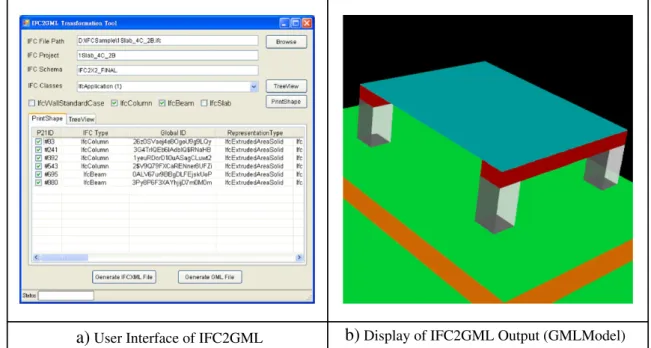
For data exchange and sharing, DataExporter can provide func-tions for exporting project data to three differentfile formats. The first is the IFC data format, which is used for data exchange with IFC-based systems. The second is the ifcxml data format, which is uti-lized for data exchange with general information management sys-tems using XML technology. The third format is the GML data format, which is used for integrating with 3D-GIS geo-data[38]. 3.5. Summary
The PIIM Framework is constructed on the basis of object-oriented techniques. Object-oriented analysis and framework design are char-acterized by features such as modularity, reusability and extensibility, which are recognized as facilitative to the evolution and the mainte-nance of application systems.
In terms of modularity, the PIIM Framework segments complex objects into manageable pieces or modules according to particular purposes, and encapsulates complex implementation details behind stable interfaces. The modules are similar to the Lego pieces which can be assembled and connected in many ways, to construct different applications easily.Fig. 6illustrates how the import function for 3D objects is developed. Users can utilize the functionalities of the DataAdapter for receiving 3D Objects, the DataManager for trans-forming data structure and the DataViewer for viewing 3D models into the application system. Hence, applications can be built quickly and development effort can be reduced.
In terms of reusability, the PIIM Framework enhances reusability by defining generic components that can be reapplied to create new applica-tions. For example, coding is achieved in the same way as calculating the percentage of scheduled progress and quality statistics in engineering projects, and so a class CCalPercentage which calculates the percentage is provided in the DataAnalyst for both to use, as shown inFig. 7.
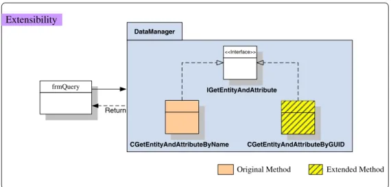
Lastly, the PIIM Framework is designed to include hook methods and mechanisms for enhancing the system with new capabilities, without requiring major changes to the system infrastructure.Fig. 8
shows an example of extensibility in PIIM Framework. The interface IGetEntityAndAttribute is used to specify the required attributes and behavior of object querying. From the research above, two positive achievements are derived for application development. One is that the same interface can be inherited to implement the different classes. Once the application is based on the PIIM Framework, the de-veloper can add new querying features to an existing application without having to change any existing code. Another is that new attri-butes and behavior can be added into the interface, which would be
<<XML Data Model >>
Key Attributes Of IFC ObjectsIFC Data Model
Reference
Fig. 5. Example for the data structure of the integrated data model.
Modularity
DataAdapter DataManager C3dObjectsAdapter C3dObjectsTreeView Return Return DataViewer AxOctagaModellerX frm3D frmMain frm4DViewupdated for the related class automatically. In this way, the functions of classes will be effectively extended.
4. Prototype system
This research prototyped a visual project management informa-tion system for a construcinforma-tion managementfirm named VisPMIS to test the feasibility of the PIIM Framework.
4.1. Engineering example
In this research, we selected an actual engineering project in the campus of National Taiwan University (NTU) as a case study. The pro-ject involved the construction of an underground parking area and an information center. As illustrated inFig. 9, the organization of this project is divided between three main participants and areas of re-sponsibility: (a) NTU, the property owner with contractual relation-ships to Company A and Company B; (b) Company A, a professional engineering and consulting service provider which provided profes-sional construction management services to NTU, while supervising and managing Company B; and (c) Company B, a constructionfirm which provided the physical workforce for the design and construc-tion of this engineering project. Each of the major project participants executed their respective project management responsibilities.
However, in this research, the majority of the work was the responsi-bility of the construction managementfirm. We analyzed the project management requirement by interviewing Company A and NTU. After interviewing NTU, we were able to understand the responsibil-ities of Company A as stipulated in the contract and as requested by the owner. After interviewing Company A, we were able to visualize the project management process in a practical context.
4.2. Requirements analysis of prototype system
The main objective of Company A was to monitor and control all aspects of a project to achieve project goals, such as completing the project on-time and to the specified cost, quality, and performance. The work performed by Company A was mainly focused on project management during engineering construction. As shown inFig. 10, the main work activities could be divided into three phases: (1) the Project Preparation Phase, (2) the Project Construction Phase, and (3) the Project Completion Phase.
During the Project Preparation Phase, the main focus of Company A before construction was project information collection and veri fica-tion. Company A obtained the planned project information from Company B and other project participants. The information included schedule information, cost information, 3D models of the project, and relevant documents. After receiving the project information,
DataAnalyst
Return
Return
Reusability
percentage of scheduled progress
percentage of quality statistic frmOne
frmTwo
CCalPercentage
Fig. 7. The reusability of PIIM Framework.
Extensibility
frmQuery
Original Method Extended Method
Return
DataManager
IGetEntityAndAttribute
CGetEntityAndAttributeByName CGetEntityAndAttributeByGUID
<<Interface>>
References
[1] H. Kerzner, Project Management: A Systems Approach to Planning, Scheduling, and Controlling, Wiley, USA, 2005.
[2] D.H. Zhong, J.S. Zhang, New method for calculating Path Float in Program Evaluation and Review Technique (PERT), Journal of Construction Engineering Management 129 (5) (2003) 501–506.
[3] W.D. Cottrell, Simplified Program Evaluation and Review Technique (PERT), Journal of Construction Engineering Management 125 (1) (1999) 16–22.
[4] M.B. Woolf, Faster Construction Projects with CPM Scheduling, McGraw Hill, USA, 2007.
[5] WALKTHRU PC Version 1.0, 3D Simulation, User's Manual, Bechtel's Software, 1991.
[6] Parsons Brinckerhoff, Corporate IT Tools SCDOT Construction and Resource Man-agement, PB Network, 2004 Issue 58.
[7] Parsons Brinckerhoff, Building Our Future, PB Network, 2005 Issue 60. [8] T. Nagasaki, K. Banno, K. Wakasugi, A. Yasaka, T. Tanimura, LINCS (Kajima Linkage
of Information for New Construction System), Proc. of the Eight International Conference on: Computing in Civil and Building Engineering, Stanford, CA, United States, 2000, pp. 518–525.
[9] F. Pena-Mora, S. Tanaka, Information technology planning framework for Japa-nese General Contractors, Journal of Management in Engineering 18 (3) (2002) 138–149.
[10] S.H. Hsieh, C.S. Chen, Y.F. Liao, C.T. Yang, I.C. Wu, Experiences on development of a 4D PLANT construction simulation system, Proc. of the 11th International Confer-ence on Computing in Civil and Building Engineering, Montreal, Canada, 2006. [11] S.H. Hsieh, C.S. Chen, Y.F. Liao, C.T. Yang, I.C. Wu, Construction director: 4D
simula-tion system for plant construcsimula-tion, Proc. of the Tenth East Asia-Pacific Conference on Structural Engineering and Construction (EASEC-10), Bangkok, Thailand, 2006, pp. 135–140.
[12] I. Howell, B. Batcheler, Building Information Modeling Two Years Later—Huge Potential, Some Success and Several Limitations, The Laiserin Letter, May 2005. [13] S. Azhar, W.A. Carlton, D. Olsen, I. Ahmad, Building information modelling for
sus-tainable design and LEED rating analysis, Automation in Construction 20 (2) (2011) 217–224.
[14] J.P. Zhang, Z.Z. Hu, BIM- and 4D-based integrated solution of analysis and man-agement for conflicts and structural safety problems during construction: 1. Prin-ciples and methodologies, Automation in Construction 20 (2) (2011) 155–166. [15] Z.Z. Hu, J.P. Zhang, BIM- and 4D-based integrated solution of analysis and
man-agement for conflicts and structural safety problems during construction: 2. Automa-tion in ConstrucAutoma-tion 20 (2) (2011) 167–180.
[16] T. Liebich, J. Wix, IFC Technical Guide, IAI, 2000.
[17] M. Halfawy, T. Froese, Component-based framework for implementing integrated architectural/engineering/construction project systems, Journal of Computing in Civil Engineering 21 (6) (2007) 441–452.
[18] J. Plume, J. Mitchell, Collaborative design using a shared ifc building model— learning from experience, Automation in Construction 16 (1) (2007) 28–36. [19] H. Schevers, J. Mitchell, P. Akhurst, D. Marchant, S. Bull, K. McDonald, R. Drogemuller,
C. Linning, Towards digital facility modelling for Sydney Opera House using IFC and semantic web technology, ITcon 12 (2007) 347–362.
[20] Y. Song, A. Hamilton, H. Wang, Built environment data integration Using nD modeling, ITcon 12 (2007) 429–442.
[21] A. Lee, M. Betts, G. Aouad, R. Cooper, S. Wu, J. Underwood, Developing a vision for an nD modelling tool, Proc. of CIB W78— Distributing Knowledge in Building Conference, Aarhus, Denmark, 2002.
[22] A. Lee, S. Wu, A. Marshall-Ponting, G. Aouad, J.H.M. Tah, R. Cooper, nD modelling — a driver or enabler for construction improvement? RICS Research Paper Series 5 (6) (2005) 1–16.
[23] D.G. Treicher, Are you missing the boat in training aid? Film and AV Communica-tion 1 (1967) 14–16.
[24] K.M. Liston, M. Fischer, J. Kunz, Designing and evaluating visualization tech-niques for construction planning, Proc. for the 8th International Conference on Computing in Civil and Building Engineering, Stanford University, CA, USA, 2000, pp. 1293–1300.
[25] K. Liston, M. Fischer, J. Kunz, Requirements and Benefits of Interactive Information Workspaces in Construction, CIFE Technical Report, Stanford University, 2001. [26] L.M. Sheppard, Virtual building for construction projects, IEEE Computer Graphics
and Applications 24 (1) (2004) 6–12.
[27] E. Collier, M. Fischer, Visual-based scheduling: 4D modeling on the San Mateo County Health Center, Proc. of the Third Congress on Computing in Civil Engineering, ASCE, Anaheim, CA, USA, 1996, pp. 800–805.
[28] K. McKinney, J. Kim, M. Fischer, C. Howard, Interactive 4D-CAD, Proc. of the Third Congress on Computing in Civil Engineering, Anaheim, CA, USA, 1996, pp. 383–389. [29] K.M. Liston, M. Fischer, J. Kunz, 4D annotator: a visual decision support tool for
construction planners, computing in civil engineering, Proc of International Com-puting Congress, Boston, USA, 1998, pp. 330–341.
[30] K.W. Chau, M. Anson, J.P. Zhang, 4D dynamic construction management and visu-alization software: 1. Development, Automation in Construction 14 (4) (2005) 512–524.
[31] K.W. Chau, M. Anson, D.D. De Saram, 4D dynamic construction management and visualization software: 2. Site trial, Automation in Construction 14 (4) (2005) 525–536.
[32] T. Huang, C.W. Kong, H.L. Guo, A. Baldwin, H. Li, A virtual prototyping system for simulating construction processes, Automation in Construction 16 (5) (2007) 576–585.
[33] N. Dawood, S. Sikka, Measuring the effectiveness of 4D planning as a valuable communication tool, Journal of Information Technology in Construction 13 (2008) 630–636.
[34] IFCsvr,http://tech.groups.yahoo.com/group/ifcsvr-users/2011.
[35] Q.W. Fleming, J.M. Koppelman, Earned Value Project Management, Project Man-agement Institute, USA, 2000.
[36] D.H. Roger, Warburton, A time-dependent earned value model for software projects, International Journal of Project Management 29 (8) (2011) 1082–1090. [37] J. Pajares, A. Lopez-Paredes, An extension of the EVM analysis for project monitoring:
the cost control index and the schedule control index, International Journal of Project Management 29 (5) (2011) 615–621.
[38] I.C. Wu, S.H. Hsieh, Transformation from IFC Data Model to GML data model: methodology and tool development, Journal of the Chinese Institute of Engineers 30 (6) (2007) 1085–1090.