Performance analysis of wavelength division- and
su bca r r ie r-m u
I t
i
pl ex i ng (W D
M
-SC
M)
t
ra nsm i ss
i
on
using fibre Brillouin amplification
Y.-H. Lee
J. Wu M.-S. Kao
H .-W. Tsao
Indexing terms Ampllfiers, Amplification
~
Abstract: A subcarrier multiplexing based optical wavelength division multiplexing system with fibre Brillouin amplification (FBA) is analysed. In the optical domain, a pump laser is tuned to amplify the corresponding optical carrier by FBA for the desired group of SCM signals. In the electrical domain, a microwave tuner is used to select the desired channel in the selected SCM group. This system has the benefits of eliminating the need for polarisation control, the ability to cancel phase noise due to the ‘squaring’ photodetection process of the selected optical carrier together with its SCM channels, and enhancement of optical receiver sensitivity by amplification of the carrier. Comparisons with other systems are also pre- sented.
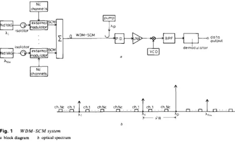
1 Introduction
Efficient multichannel transmission can be achieved with an optical carrier using a subcarrier multiplexing (SCM) technique [l, 21 which provides an attractive feature for exploiting the wide bandwidth of single-mode fibres with commercially available microwave electronic com- ponents. Recently, some systems that combine wave- length division multiplexing (WDM) and SCM to further increase transmission capacity have been reported [3, 41. These systems use an optical wavelength filter to select the desired group of SCM signals which is transceived with the intensity modulation/direction detection (IM/DD) technique. However, the additional loss penalty introduced by the wavelength filter restricts the system operating range.
In this paper we propose a WDM-SCM system as shown in Fig. 1 where channel selection consisted of two stages. The first stage selection in WDM (optical tuning) is based on the selective amplification of the chosen optical carrier by employing fibre Brillouin amplification (FBA) [5, 61 prior to photodetection. This is possible because the residual optical carrier in the spectra of SCM
~~
Paper 87823 (E13), first received 19th August 1991 and in revised form 14th January 1992
Y.-H. Lee. J. Wu and H.-W. Tsao are with the Department of Electrical Engineering, National Taiwan University. Taipei, Taiwan, Republic of China
M . 4 . Kao is with the Department of Communication Engineerin& National Chiao Tung University, Hsincha, Taiwan, Republic of China. 272
signals [7] can be easily amplified by narrowband Bril- louin amplification with a tunable pump laser. The second stage selection in SCM (microwave tuning) is accomplished by tuning the microwave voltage control oscillator (VCO) to cause the desired SCM channel falling into the passband of a bandpass filter (BPF), then it can be demodulated to obtain the baseband signal.
In this system, we use an extremely narrowband optical amplifier to amplify the residual optical carrier of the SCM system, which is achieved elegantly within the transmission fibre by backward stimulated Brillouin scattering (SBS). This process has a bandwidth of 15-25 MHz for CW pump and it can be broadened by frequency modulating the pump laser [8, 91. To obtain Brillouin amplification, it is necessary to have a pump laser at the receiver to feed optical energy back along the fibre towards the transmitter. Significant gains can be achieved at milliwatt-pumping power levels in a long fibre [IO].
This system has some advantages. First, the need of polarisation control can be eliminated and phase noise can be reduced [ I l l . Because the polarisation state and phase noise of SCM channels and their corresponding optical carrier are nearly the same; after the squaring photodetection process, the cross terms of the optical carrier and SCM channels thus produce microwave signals without the deterioration due to polarisation mis- match and phase noise [SI. Secondly, the pre- amplification of a modulated optical signal by an extremely narrowband amplifier enhances the signal-to- noise ratio [ll]. Thirdly, the wavelength selection is accomplished by the FBA together with its optical ampli- fication without the insertion loss caused by the optical wavelength filter.
2 Analysis
2.1 System description
Consider a WDM-SCM system as shown in Fig. 1. At the transmitter, we modulate N , VCO outputs by corres- ponding baseband signals (called ‘channels’) and combine these signals to produce the composite microwave signal. The baseband signals may be either analogue or digital. Then we use these signals to modulate the corIesponding
N , lasers by N , external amplitude modulators, respec- tively. The N w optical carriers, each carrying their corre- sponding N , subcarriers, are then multiplexed to form the WDM-SCM signal which includes N , N , channels.
The spectra of the subcarriers expand symmetrically around their corresponding wavelength ii as shown in Fig. 2; these 2 N , sidebands come from the N , channels.
where AuB and AuP are the full widths at half maximum (FWHM) of the Brillouin-gain profile and pump laser, respectively; uB is the Brillouin frequency shift with a cor-
d o t o o u t p u t . . . n . n n . . c h N c c h 1 c h l chNc chNc c h l c h l chNc n n n. . n Fig. 1 W D M - S C M system o block diagram b optical spectrum
*\
r---
- - - - 1At the receiver, we tune the frequency of the pump laser to amplify the desired optical pilot carrier by FBA. This process generates noises including the amplified spontaneous emission noise (ASEN) [6, 121. The optical
signal and noises are then converted by the photo- detector into a photocurrent. The noises include the spontaneous emission, the thermal noise, the shot noise, the intermodulation distortion (IMD) [l], the beat noises of unselected optical carriers and their own SCM chan- nels, the signal-spontaneous beat noises, and the beat noises between any cross-wavelength terms (see Fig. 3).
# I
r - - - 1
I I
L
responding peak gain go without considering the effect of
Aup
.
For AuB $ AvAAu, is the FWHM of the Stoke wave),
we may consider all the Stoke waves amplified by the SBS gain G , which can be expressed by [15] (see Fig. 4 )
G = exp
[z]
where P is the pump power, a is the absorption coeffi- cient ( m - '), A , is the effective core area of the fibre and the factor 2 accounts for the random polarisation of the waves.
The noise in FBA results from the spontaneous Bril- louin scattering. In the undepleted pump condition, the
photon per mode, for long fibre length, as given by [ 6 , 2.2 Fibre brillouin amplification and amplified
spontaneous emission noise (ASEN)
We assume that the Brillouin gain has a Lorentzian spec- ASEN can be in terms of spontaneous tral profile given by [ 151
I
cross-wovelengthFig. 3 Noise spectra in W D M - C S C M system
with M and
r
defined asand
( 5 )
where hv, is the Stoke shift energy, k is the Boltzmann
constant and T is the absolute temperature.
+pump $ 1
dB ~- -&
Fig. 4
together with gain profile
Optical spectrum of the selected kth wavelength and pump laser
Then we may obtain the total ASEN power Psp and its electric field as [ 121
P s p = N,(v)hv dv (6) ( 7 ) E,,@) =
JP,,)
cos ( O A j t+
9,)
where wAi and QS, are the central frequency and the random phase of the ASEN. Because of random polarisa- tion, the effective power is only Psp/2.
J"
2.3 Selection in WDM
If we want to choose the ith optical carrier with fre- quencyfAi (the ith wavelength) in the WDM, we have to tune the pump laser frequency, f p m p , to amplify the
desired optical carrier as
fpm,
= f 2 ,+
0, (8)Then the photocurrent at the output of the photo- detector, i(t), can be expressed as
i(t) = R
1
E ,+
E ,+
E +
%
+
E,,1'
( 9 )where R (A/W) is the responsivity of the photodetector. The last term in the above equation is given in eqn. 7 . The first four terms which represent, respectively, the electric field of the selected ith optical carrier amplified by FBA (Eo), the electric fields of the selected SCM
signals in the ith carrier (E,), the electric fields of the
total unselected optical carriers
(E),
and the electric fields of the total unselected SCM channel(q),
are given as(10) E&) = J ( 2 G P s ) COS (w,,t
+
@A,)E&) =
1
m l , ,J ( P S / 2 ) { c o s C(wl, - wl)t+ @*,I
NcI = 1
+
cos [(OL,+
w,)t+ %,I)
where P , is the received power of each optical carrier without amplification (assumed equal for all lasers), G is the gain of SBS, wI is the microwave subcarrier fre-
quency, ml, is the modulation index of the Ith channel in
the kth optical carrier, mi, and
mi,
are the frequency and phase noise of the selected ith optical carrier, and wAk andmlk
are the frequency and phase noise of the unselected kth optical carrier. If optical modulation depth per channel is the samemf, k = ( 1 4 )
then the total effective optical modulation depth per laser, m, , can be expressed as
mo = m J ( N J ( 1 5 )
By substituting eqns. 14 and 15 into eqns. 1 1 and 13, we obtain
+
cos m l ,+
w1)t+
@ L k l l
( 1 7 )Because each optical carrier Ai in WDM is separated widely enough and the frequency response of the photo- detector is relatively slow compared with the frequencies of cross-wavelength terms (the cross termsLrisingJrom different opticalsarriers a r e 2 R E , E , , 2 R E , E , , 2 R E , E , , 2 R E , E,,, 2REs E, and 2REs E,, in eqn. 9), we may write the photocurrent as
2.4 Selection in SCM
When we want to choose the jth SCM channel in the ith WDM group, we may tune the frequency of the micro- wave VCO, fvco, to cause the desired jth channel to fall into the passband of BPF with centre frequency
fJlfj
-fvco
I
=fc) and bandwidth B (assuming that the VCO mixer only changes the signal frequency). Then we may obtain the bandpassed signal current asisiss(t) = B P F { 2 R E 0 E J 2 COS (wvco t) ] }
= 2Rm, P ,
/(
2)
cos (wc t )where B P F [
' 1
represents the operation of bandpass fil- tering. We see that the phase noise in eqn. 19 has been cancelled. The bandpassed noises in eqn. 18 can be expressed, together with their variances, as~ s c M ~ ( ~ ) = BPF{ZRE,E,C2 COS (wvco
t)l}
= 2 ( N w - 1)Rm, P , cos ( w C t ) / J ( N c ) (20) ( 2 1 )
var (iSCMn) = 2 ( N , - 1)R2m:Pi/Nc
= RmoJ(2Ps p s p i N c )
var (iSig-J = RZm2 P , P,,,/N,
isig-sp(t) = B P F { ~ R E s EsJ2 COS ( ~ Y C O
t)l}
x cos (Uc t
+
@A, -a)s,)
( 2 2 )(23) (24)
var (it,,) = 4 N F k T B / r (25)
var (ish) = 2 e R B P d G
+
N w - 1+
Nwm,2/2)where e , N F and r are the electron charge, the amplifier
noise figure ( 6 dB), and the load resistance. isCMn rep- resents the interference from the unselected optical car- riers mixed with their own SCM channels. isig-ap is the signal-spontaneous noise. n e D C power in eqn. 18 [that is, DC terms in R(E:
+
E:+
E:+
E;)] results in theshot noise, is,. The spontaneous-spontaneous noise (i.e. RE:, in eqn. 18) is relatively small, and the beat noise of the selected optical carrier and the spontaneous noise (i.e. 2RE,E,,) are not located in the passband of the BPF under the condition that the frequency stability of the pump source is precisely controlled. When the pump source is not located exactly as given in eqn. 8 and there is some random frequency variation, the beat noise of the selected optical carrier and the spontaneous noise may have to be considered in terms of the random frequency variation of the pump sources. In such a case, the Bril- louin gain may also change owing to this random fre- quency variation of the pump laser.
2.5 Derivation of CNR
We shall assume that either the external modulator is perfectly linear [13, 141 or the predistortion linearisation technique is used to make the intermodulation distortion less than -60 dBc [ 1 4 ] . Furthermore if we take the fre- quency allocation to be single-octave, then the inter- modulation distortion will be small and can be ignored.
Taking the channels in WDM-SCM to be uncor- related with each other, we may obtain the CNR at the output of the BPF from eqns. 19-25 as
m, = 0.25, 0.3 and P , = - 35, - 30 dBm, respectively.
The CNR increases as the received power, the total optical modulation depth and the pump power increase. The CNR value saturates at a pump power of 2.25 mW which is determined by the shot noise and the thermal noise when these two noises are of the same order as shown in Fig. 6. Taking m, = 0.25 and P , = - 3 5 dBm,
I
1 5 2 2 5 3 3 5 4
pump power P, mW Fig. 0
P , = - 35 dBm
Bandpass noise current7 against pump power f o r m , = 0.25 and
we can plot the various noise powers at the output of the BPF against pump power as shown in Fig. 6. In the
lower pump power region, the thermal noise, the inter- ference from the unselected optical carriers mixed with their own SCM channels and the shot noise are dom- inant; whereas in the higher pump power region, the shot noise is dominant and the other noises can be ignored. We also plot the CNR against the channel number of the SCM, N e , in terms of the number of the optical carriers in the WDM, N , , for P,,,, = 2.5 mW, P , = - 2 5 dBm
and m, = 0.35 as shown in Fig. 7. The CNRs increase as
N , and N , decrease. We also see that as N , changes
from 10 to 50, the CNR varies approximately from 34 to 27dB; but when N , changes from 1 to 10, the CNR
remains almost unchanged. Because the optical modula- tion depth per SCM channel decreases linearly with the number of channels, which in turn reduces the CNR, whereas the optical modulation depth is not affected at all by the number of wavelengths even though receiver noise increases with this number, this effect is minimal.
2RZm:Pg G I N ,
var (iSCMn)
+
var (iSi&+
var (ish)+
var (it),) C N R = - - R2m:P: G I N , R ~ ~ : P , I N , [ ( N , -w,
+
p S p i 2 i+
e R B P d G+
N , - 1+
N , m:/2)+
2 N F k T B l r ( 2 6 ) 3 ExamplesThe parameters of optical fibre are given by A , = 47 pm2,
a = 9.5 x m - l (0.41 dB/km), g, = 4.6 x l o - "
m/W, uB = 13 GHz, and AuB = 22 MHz at 1.32 pm wave-
length [ l o ] . For a system with R = l [ A / W ] ,
B = 100 MHz, N , = 20, and N , = 5 , we can obtain the
CNR against the pump power as shown in Fig. 5 for 34, m D (I L
"
m0=025 24 - 22 - 2 0 - I t '1 1 5 2 5 3 5 pump power P, mW Fig. 5 - 30 dBm B = 100 MHz N, = 5 N , = 2 0IEE PROCEEDINGS-J, Vol. 139, N o . 4 , A U G U S T 1992
C N R against pump power P f o r m, = 0.3, 0.25 and Ps = - 3 5 ,
26l 10 15 20 2 5 30 35 40 45 5 0 I channel number,N,
Fig. 7
numbers of optical carriers in the W D M N , for P,,, = 2.5 mW
P, = - 2 5 dBm
C N R against channel number of the C S C M , N , . for various
m,, = 0.35
This system suffers less from the interference of the unselected optical carriers mixed with their own SCM channels, i,, ,, and the shot noise is determined mainly by the gain G as shown in eqns. 21 and 24, therefore the CNR value is not affected much by the wavelength number, N w
.
4 Comparison
4.1 CSCM system using local oscillator, IMJDD SCM system using semiconductor laser amplifier and SCM system using Brillouin amplifier
Here we consider three different systems:
(a) the CSCM system (with the single-octave frequency allocation) using phase modulation (PM) and a local oscillator (LO) with power P,, [I]
(b) the IM/DD SCM system using a travelling-wave semiconductor laser amplifier (SLA) [ 1 9 , 2 0 ]
( c ) our amplitude modulated (AM) SCM system using a Brillouin amplifier with pump power P,,,,
.
We denote the CNRs of these three systems as
CNRLO,,,,
,
C N R S L A , ~ , , and CNRFBA,,, , respectively. The improvement factors in receiver sensitivity [ 2 0 ] , defined as the ratio of the receiver sensitivity, P E , with the use of electronic preamplifier only over the receiver sensitivity, P , , in the presence of local oscillator, the travelling-wave preamplifier and Brillouin amplifier are represented by YLO,~,,, ysLASCM9 and Y F B A ~ , , , respectiveb.They can be expressed as (see Appendix 7 ) ,
( 2 7 )
- 0 . 5 R Z P , , P , b 2
-
var (iIh)
+
2eREPLo+
h3 K , R’P,, P,a6/32 ( 2 8 ) RPLo{2eE+
, / [ 4 e Z E Z+
2azvar ( i r h ) Z ] }2[var (ilh)
+
2eREPLo]Y L O C S C M =
where Z
=
CNR-’ - h , K , b4/16 in eqn. 28.b
is the PM index, h, takes into account the spectral form of inter- modulation distortion and the associated filtering and K , is the number of third-order intermodulation distortion as given in Reference 1. Also,C N R S L A S , ~ (30b) [ 2 var (i,,)CNR]”’ R m P E = CNRFBA,,, - R Z m 2 P i G - R 2 m 2 P s P $ 2
+
eRBP,(G+
m2N,J2)+
2 N F k T E / r ( 3 1 ) m [ 8 var (i,h)]1’2G C N R 1 i 2 [ U+
d(
U’+
8 Y F B A ~ , ~ = ( 3 2 ) 276where U (Rm2P,,/2)
+
eE(G+
m 2 N J 2 ) in eqn. 32.v i ,
qo and 7. in eqn. 29 are the input coupling efficiency of the amplifier, the total optical loss between amplifier and photodiode, and the photodiode quantum efficiency(qe = Rhu/e), respectively. P , in eqns. 27, 29 and 31 rep-
resent the received signal power of the CSCM system using LO, the total incident power on the SLA in the IM/DD SCM system, and the received signal power of the SCM system using FBA without amplification. P E in eqn. 306 is the receiver sensitivity for an IM/DD SCM system using only electronic preamplifier. m is the channel AM index (assumed equal for all channels). The third-order IMPS in eqn. 29 are 1 5 - 2 0 d B below the thermal noise and thus are negligible [21]. The other noise terms in eqn. 29 can be expressed as
u & ~ , = R 2 F ( G - 1) U& = R’(G - 1)2nspm, AV
(33) (34)
From Reference 22 we can find that for a semiconductor optical amplifier with gain G of 20 dB, noise figure F of
5 dB, population inversion factor nsp of 2.2, number of
transverse modes m, of 2, optical bandwidth Ao of about 50 nm, and fibre-to-amplifier coupling loss of 3 dB can provide a net fibre-to-fibre gain of 12 dB. Then
uii
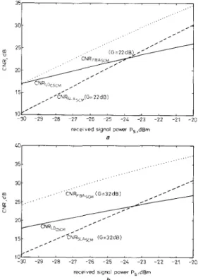
- s p is 1.2 x 10-’9AZ/Hz/mW and u,6-sp is 1.6 xIf we assume that all three systems have equal modu- lation index per channel = m = 0.1 and N c = 20, we
may compare their CNR against P , for PLO = Ppump = 0,
1.5 dBm, G = 2 2 , 3 2 dB as shown in Figs. 8a and b. A4/Hz.
3
5
1
25
!
-30 -29 -28 -27 -26 -25 -24 -23 -22 -21 - 2 0 received signal pow, P,,dBm
a LO , I , I , , , I ~ C N R ~lG=3ZdB) L ~ ~ ~ 1 5 , , 10 -30 -29 -28 -27 -26 - 2 5 -24 - 2 3 - 2 2 -21 -20 received sigml power PS.dBm
b
Fig. 8 C N R of the CSCM system using LO, of the IMIDD SCM system using S L A , and of the S C M using F B A against received signal
power P, for N , = 20, fi = m = 0.1 a PLO = P,,, = 0 (corresponding lo G = 22 dB) B = 100 MHZ, 7, = 9, = n s ’1. = 0.8 R = I [A/W] h P,, = P,,, = 1 5 dBm (corresponding to G = 32 dB)
The CNR of the CSCM system is better in the lower signal power region; the CNR of the IM/DD system with SLA is better in the higher signal power region. However, the CNR of our SCM system with FBA performs better than the former two cases. Increasing the pump power from OdBm to 1.5dBm, we see that the CNR of our SCM system using FBA increases by about 7 dB, but the CNRs of the CSCM system using LO and the SCM system using SLA remain unchanged (that is, in the satu- ration region) as shown in Figs. 8a and b, respectively. To see the improvement of receiver sensitivity between the CSCM system with L O and the SCM system with FBA, we may compare yLOCSCM and yFBAsCM under the same PLO and P,,,, for CNR = 16 dB, 18 dB, respectively, as shown in Fig. 9. The sensitivity improvement of the SCM system using FBA is superior to that of the CSCM system using LO at higher pump or LO power; the improvement increases as the CNR decreases. Also, the Brillouin approach is intrinsically simple and polarisa- tion independent, whereas a coherent system is highly complex, polarisation dependent and costs significantly more. We compare the improvement between the SCM system with FBA and the IM/DD SCM system with SLA against the same gain G for CNR = 16 dB, 18 dB, respec- tively, as shown in Fig. 10. The receiver improvement of the SCM system using FBA is better in the lower gain region; but in the higher gain region that of the IM/DD SCM system using SLA is better. In general, for all amplifier gains of interest, a system that uses a semicon- ductor amplifier is better than the Brillouin approach. O n the other hand, the polarisation dependence of semi- conductor amplifiers, the difficulties of optical coupling, and stability have to be considered in practical imple- mentation.
I
'LoCSCM
''-2 -15 -1 - 0 5 0 0 5 1 1 5 2
the LO or Pump p o w r , d B m
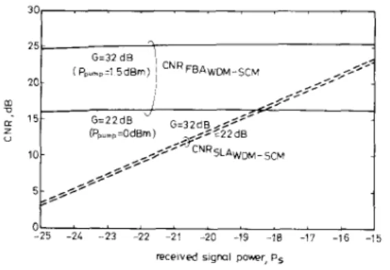
4.2 I M / D D WDM-SCM system using optical preamplifier and WDM-CSCM system using FBA
If we consider an IM/DD WDM-SCM system [ 3 , 41 as shown in Fig. 11 which employs a travelling-wave SLA
2 4 , 7 ' ' ' I
121 " " " " ' I
22 23 2L 25 26 27 28 29 3 0 31 32 g o i n , d 6
Fig. 10 Improvement ofreceiver sensitivity of the SCM system using F B A and l M / D D SCM system using S L A under the same gain G with C N R = 14 dB, 18 dB, respectiuely N, = 20 m = 0.1 R = I[A/W] q. = 0.8 B = 100 MHr q , = q , = O S
as the preamplifier [19, 201 and uses the improved integrated-optic acousto-optic tunable filter (IAOTF) with total single-mode fibre-to-fibre insertion loss, qf [23,
241, to select the desired wavelength in the WDM, then the CNR of such a system can be expressed as
C N R S L A W ~ ~ - ~ ~ ~
(35)
From eqns. 26 and 35, we can obtain the CNR of WDM-SCM system using Brillouin amplifier and that of
the IM/DD WDM-SCM system using IAOTF with SLA
against received signal power P , as shown in Fig. 12 for = 8.7 dB [ 2 3 ] ,
v i
= '1, = 0.5 ( 3 dB IOSS), R = l(A/W),qe = 0.8, m = 0.1 B = 100 MHz, G = 22 dB and 32 dB,
respectively. For gain varying from 32 dB to 22 dB, the CNR of the WDM-SCM system using FBA is improved by 10 dB, that of the WDM-SCM system using SLA is improved by 4 dB. For the received power of -25 dBm, the CNR of the WDM-SCM svstem usine FBA is better Fig. 9 Improuement ofreceiver sensitiuity o f C S C M system using LO,
and the S C M system using FBA, respectively, under the same PLO and
than that Of the WDM-SCM 'sing sLA-by more than
l o dB; for the received Power of - 15 dBm, the CNR of
Pmmn . . the WDM-SCM using FBA with G = 32 dB is still better
CNR = 16 dB, 18 dB, respectively, for N, = 20, fl = m = 0 I than that of the WDM-SCM using SLA. In the
B = 1M) MHz WDM-SCM using SLA, there is an IAOTF which
induces a high insertion loss (8.7 dB) and this causes its
S L A
lrl
Fig. 11
IEE PROCEEDINGS-J, Vol. 139, No. 4, A U G U S T 1992
System block diagram o f l M / D D W D M - S C M system employing I A O T F and S L A
30 25 20 m
2-
1 5 - z”
10- 5 -received sigml poker, p5
Fig. 12 C N R of the W D M - S C M system using FBA and the IMIDD W D M - S C M system using I A O T F and S L A against received signal power Ps 7, = 8.7 dB 7, = 7. = 0.5 (3 dB loss) G = 22 dB and 32 dB, respectively R = I CA/W] 7, = 0.8 m = 0 1 and B = 100 MHz . , .
.
, , , , , ~ G=32dB’,
(P,um,~l 5dBm) I C N R F B A W D M - S C ~,.?
,,, --.:-
~ ~ I ,<:, , -5 G=22dB ~ = 3 ~ d ~ ~ ~ > ’ (Ppum,=GdBm) ,:-:22dB**+
*[email protected],*/
r O ’ ’ ’ ’ . . . ” 5 ConclusionA WDM-SCM system employing optical SBS narrow- band amplification to select the desired channel is pro- posed in this paper. This system has the benefits of eliminating the need for polarisation control, cancelling the phase noise, and enhancing optical receiver sensitiv- ities by amplification of the optical carrier.
At the receiver, we use a tunable pump laser to select the optical carrier in WDM by FBA and obtain and het- erodyne IF signal without its being degraded by the phase noise. With appropriate received power and total optical modulation depth, the required CNR is achiev- able. The CNR is not influenced seriously by the number of optical carriers because the value of Brillouin gain is large and the beat noise produced by other unselected optical carriers with their SCM channels is not amplified. We believe that such a structure may be attractive for the SCM system in which residual optical carrier power is stronger than its channels. Here we not only make use of this optical carrier but also achieve heterodyne detec- tion without degradation of the phase noise.
We also see that our SCM using FBA outperforms the
CSCM using LO and the SCM using SLA. As for the sensitivity improvement, the SCM using FBA is better than the CSCM using LO at the same pump and LO level in the high power range. The receiver improvement of the SCM using FBA is superior to that of the SCM using LO in the lower gain region. The WDM-SCM system using FBA does not need a wavelength filter, therefore such a structure may also be superior to the WDM-SCM system using SLA which has a high inser- tion loss wavelength filter for wavelength selection.
6 References
1 GROSS, R., and OLSHANSKY, R.: ‘Multichannel coherent FSK experiments using subcarrier multiplexing techniques’, J . Lightwave
Techno/., 1990,8, (3), pp. 406-415
2 WAY, W.I.: ‘Subcarrier multiplexed lightwave system design con- siderations for subscriber loop application’, J . Lightwave Techno/., 1989.7, ( l l ) , pp. 1806-1818
278
3 WESTLAKE, H.J., HILL, G.R., WICKENS, G.E., and CAVA- NAGH, B.P.: ‘Subcarrier multiplexed transmission using wave- length division multiplexing and optical amplifier’, Electron. Lett.,
1989,25, (lo), pp. 632-634
4 LIEW, S.C., and CHEUNG, K.W.: ‘A broad-band optical network based on hierarchical multiplexing of wavelengths and R F sub- carriers’, J . Lightwave Technol., 1989,7, (1 l), pp. 1825-1835 5 CHRAPLYVY, A.R., and TKACH, R.W.: ‘Narrow tunable optical
filter for channel selection in densely packed WDM systems’, Elec-
tron. Lett., 1986, 22, pp. 1084-1085
6 TKACH, R.W., CHRAPLYVY, A.R., and DEROSIER, R.M.: ‘Per- formance of a WDM network based on stimulated Brillouin scat- tering’, IEEE Photonics Technol. Lett., 1989, (5). pp. 11 1-1 12 7 GROSS, R., OLSHANSKY, R., and SCHMIDT, M.: ’Coherent
FM-SCM system using DFB lasers and a phase noise cancellation circuit’, IEEE Photonics Technol Lett., 1990,2, ( I ) , pp. 66-68 8 ATKINS, C.G., COTTER, D., SMITH, D.W., and WYATT, R.:
’Aodication of Brillouin amdification in coherent outical transmis- si&’, Electron. Lett., 1986,22, pp. 556-558
9 OLSSON, N.A., and VANDER ZEIL, J.P.: ‘Characteristics of a semiconductor laser pumped Brillouin amplifier with electronically controlled bandwidth: J . Lightwave Technol., 1987, LT-5, pp.
147-153
I O COTTER, D.: ‘Stimulated Brillouin scattering in monomode optical fiber’, J . Opt. Commun., 1983,4, pp. 10-19
1 1 ARNAUD, J.A.: ‘Enhancement of optical receiver sensitivities by amplification of the carrier’, lEEE J . Quantum Electron., 1968, Q 6 4 , (1 l), pp. 893-899
12 MOCHIZUKI, K., EDAGAWA, N., and IWAMOTO, Y.: ‘Ampli- fied spontaneous Raman scattering in fiber Raman amplifier’, J .
Lightwave Technol.. 1986, LT-4, pp. 1328-1333
13 CHILDS, R.B., and OBYRNE, V.A.: ‘Multichannel AM video transmission using a highpower Nd :YAG laser and linearized exter- nal modulator’, J . Se/. Area Commun., 1990,8, (7), pp. 1369-1376 14 BODEEP, G.E., TARCIE. T.E.: ’Comparison of second and third
order distortion in intensity modulated InGaAsP lasers and on LiNbO, external modulator’. Tech. Dig. Opt. Fiber Conf. (Houston TX), Feb. 6-9, 1989
15 AGRAWAL, G.P.: ‘Nonlinear fiber optics’ (Academic Press. Inc., New York, 1989) chap. 9
16 SMITH, R.G.: ’Optical power handling capacity of low loss optical fibers as determined by stimulated Raman and Brillouin scattering’,
Appl. Opt., 1972, ( 1 I), pp. 2489-2494
17 ABUELMAATTI, M.T.: ‘Carrier-to-intermodulation performance of multiple FM/FDM carriers through a GaAlAs heterojunction laser diode’, IEEE Trans., 1985, COM-33, (3), pp. 246-248 18 OLSHANSKY, R., LANZISERA, V.A., and HILL, P.M.: ‘Sub-
carrier multiplexed lightwave systems for broadband distribution’, J .
Lightwave Technol., 1989, LT-7, (9). pp. 1329-1341
19 JOYCE, G.R., LANZISERA, V., and OLSHANSKY, R.: ‘Improved Sensitivity of 60 video channel FM-SCM receiver with semicon- ductor optical preamplifier’, Electron. Lett., 1989, 25, pp. 499-501 20 OLSHANSKY, R . : ‘Optical preamplifiers for subcarrier multiplexed
lightwave systems’, Electron. Lett., 1987, 23, pp. 1196-1 197 21 OLSHANSKY, R., and LANZISERA, V.A.: ‘64 channel FM video
subcarner multiplexed optical communications system’, Electron.
Lett., 1987.23, pp 1196-1197
22 MUKAI, T., and SAITOH, T.. ‘5.2 dB noise figure in a 1.5 pm InGaAsP travelling-wave laser amplifier’, Electron. Lett., 1987, 24, pp. 216-218
23 CHEUNG, K.W., LIEW, S.C., and LO, C.N.: ‘Simultaneous five- wavelength filtering at 2.2 nm wavelength separation using integrated-optic tunable filter with subcarrier detection’, Electron.
Lett.. 1989, 25, (25). pp. 636-637
24 HEFFNER, B.L, BARAN, D.A., YI-YAN, A., and CHEUNG, K.W.: ‘Improved acoustically-tunable optical filter on x-cut LiNbO,’, Electron. Lett., 1989, 24, pp. 1562-1563
7 Appendix
The CNR and receiver sensitivity P E of a CSCM system which uses only an electronic preamplifier can be expressed as
(36) 0 . 5 R 2 P 2 a 2
var (ith)
+
2eRBPE+
R’h, K , P i a 6 / 3 2 C N R =(37) IEE PROCEEDINGS-J. Vol. 139, No. 4 , A U G U S T 1992
where Z C N R - ’ - h , K , b4/16. From eqn. 27, we can obtain the receiver sensitivity P , and the improvement of the receiver sensitivity for the system using a local oscil- lator, respectively, as
var (it,,)
+
2eRBP,,0.5R2B2P,, Z
Ps =
P E [in eqn. 371
yLOcscv = Ps [in eqn. 381
RP,,[2eB
+
J ( 4 e 2 B 2+
2B2i:,,Z)]2[var (it,,)
+
2eRBP,,] (39)- -
From eqn. 31, we may express the receiver sensitivity P , for transmission of only one wavelength (that is, N , = 1 in eqn. 26) and m : / N , = m2 as
(=)Pi - R U P , - 2 N F k T B / r = 0
where U
=
(Rm2PSp/2)+
eB(G+
m2N,-/2). Then we cansolve eqn. 4 to obtain P , as,
(41) U
+
J[U’+
8 ( m 2 G / C N R ) N F k T B / r ]2 ( R m 2 G / C N R ) P , =
and the improvement in the receiver sensitivity using FBA can be expressed as
Y F B A ~ ~ ~ P,[in eqn. 3061 P , [in eqn. 411 C N R ’ ” { U
![Fig. 10 Improvement ofreceiver sensitivity of the SCM system using F B A and l M / D D SCM system using S L A under the same gain G with C N R = 14 dB, 18 dB, respectiuely N, = 20 m = 0.1 R = I[A/W] q](https://thumb-ap.123doks.com/thumbv2/9libinfo/7746893.148445/6.932.464.748.159.355/fig-improvement-ofreceiver-sensitivity-using-scm-using-respectiuely.webp)