國立交通大學
多媒體工程研究所
碩 士 論 文
一個 IEEE 802.16j 移動式中繼站改進換手
延遲的預先認證機制
A Pre-Authentication Scheme to Minimize Handover
Latency on IEEE 802.16j Moving RS Mode
研 究 生:章瑋芸
指導教授:陳耀宗 教授
一個 IEEE 802.16j 移動式中繼站改進換手延遲的預先認證機制
A pre-authentication scheme to minimize handover latency on IEEE
802.16j moving RS mode
研 究 生:章瑋芸 Student : Wei-Yun Chang
指導教授:陳耀宗 Advisor : Yaw-Chung Chen
國立交通大學
多媒體工程研究所
碩士論文
A Thesis
Submitted to Institute of Multimedia Engineering College of Computer Science
National Chiao Tung University in Partial Fulfillment of the Requirements
for the Degree of Master
in
Computer Science
July 2010
Hsinchu, Taiwan, Republic of China
一個 IEEE 802.16j 移動式中繼站改進換手延遲的預先認證機制
學生 : 章瑋芸 指導教授 : 陳耀宗 博士
國立交通大學多媒體工程研究所
摘要
在無線網路通訊中,IEEE 802.16 (WiMAX) 是一項越來越普及的技術, 而IEEE 802.16j 則是增加了多躍式中繼站來擴展通訊的涵蓋範圍。在標準中,移 動式中繼站是指在行動通訊系統上加入中繼站,而本論文是在移動式中繼站的其 中一種特殊應用上,將中繼站設置在大眾交通運輸工具之上,使得裡面的使用者 可以透過此中繼站跟無線網路基地台做連結。然而在移動中,為了維持執行交遞 時的安全性,必須重新做一次認證,但這會浪費過多的時間在交遞的中斷時間上, 而往往造成上層服務的中斷。 在移動式中繼站的機制下,使用者移動到另一個基台時,只需執行網路層 的交遞程序,而媒體存取控制層的交遞程序則交給移動式中繼站來執行。而本論 文所提出的方法是將媒體存取控制層的交遞程序中,影響中斷時間最大的認證程 序提前至使用者尚未移動到目標基台前執行,進而減少了大量使用者在交遞程序 的中斷時間,改進了通訊的傳輸品質。我們設計了一套模擬實驗,在FMIPv6下, 不管是 predictive 模式還是 reactive 模式都能有效地減少交遞程序的中斷延遲, 而在 predictive 模式下還可降低封包的遺失率。A pre-authentication scheme to minimize handover latency on IEEE
802.16j moving RS mode
Student: Wei-Yun Chang Advisor: Dr. Yaw-Chung Chen
Institute of Multimedia Engineering
National Chiao Tung University
Abstract
IEEE 802.16 (WiMAX) is becoming one of the popular technologies in wireless communications. Multi-hop relay station (RS) is used to extend the coverage area in IEEE 802.16j. Mobile RS (MRS) is a relay station that is used while in motion. A MRS mounted on a vehicle is a special application case for the research in this thesis. The MRS provides a fixed access link to the end mobile terminals riding on a vehicle. In order to maintain the security of wireless communications, re-authentication should be considered when the mobile station (MS) performs handover. However, it usually wastes too much time that may interrupt higher layer applications during a handover.
When a MS moving together with MRS changes BS for higher signal quality or better QoS, it performs network layer handover procedure while MRS performs link layer handover procedure. In this thesis, we proposed a pre-authentication scheme to reduce the interruption time of link layer handover by performing the authentication procedures before the MS roams to another BS. We developed a simulation experiment to evaluate our scheme. The result shows that with Fast Mobile IPv6, our scheme is able to reduce the interruption latency efficiently both in predictive mode and reactive mode, as well as reduce the packet loss rate in predictive mode.
誌謝
能夠完成這篇論文,首先衷心感謝我的教授陳耀宗老師。在研究階段中,陳 老師總是提供卓越的指導、全力的支持、以及溫暖的鼓勵;他淵博的知識、豐富 的經驗、以及正確的判斷也在其平日諄諄教誨之下指引我前進,而陳老師這些做 人與做事的特質的確都對我以及實驗室同學深具莫大的啟發與無窮的裨益。 我也要感謝本校多媒體通訊實驗室的同學:振華學長、俊利學長、育嘉學 長、振全、紀寰、吟珊、嘉瑋以及學弟們,因為你們在各方面給我的協助與建議, 讓我的研究生涯過得既充實又有長足的進步。由於你們的共同陪伴,我有了更深 層的體驗:美德與智慧不能獨立達到最高的境界,所以需要朋友的互助與推愛。 最後我要感謝父母、長輩、家人、與親戚;你們的厚愛、照顧、與支持,為 我過去、現在、與未來的人生增添絢麗的色彩!這些就是我此生幸福快樂的不歇 之泉。我願將這篇論文獻給你們,以回報你們的慈愛於萬一!Contents
Abstract in Chinese ... i Abstract in English ... ii Contents……….iv Table List ... v Figure List ... vi 1 Introduction ... 1 2 Background ... 4 2.1 IEEE 802.16j ... 4 2.1.1 MMR network ... 42.1.2 MRS on Vehicle Usage Model ... 5
2.2 Handover Protocols ... 6
2.2.1 MRS Handover ... 6
2.2.2 Mobile IP ... 8
2.2.3 Fast Mobile IPv6 ... 9
2.3 Authentication Mechanism ...11
2.3.1 Authentication architecture ... 11
2.3.2 EAP-TLS... 13
2.3.3 Key Derivation ... 15
2.4 Related Works ... 16
2.4.1 A Fast Handover Mobility Scheme over 802.16j Moving RS Mode . 16 2.4.2 Pre-authentication Mechanism... 19
3 Proposed Scheme ... 21
3.1 Network Model ... 21
3.2 MAC Management messages ... 22
3.3 Main Scheme ... 27
3.3.1 Predictive Mode ... 28
3.3.2 Reactive Mode ... 30
4 Analysis and Simulation ... 32
4.1 Numerical Analysis ... 32
4.2 Simulation and Results ... 38
5 Conclusions ... 44
Table List
Table 3.1 MOB_MSHO-REQ message format ... 23
Table 3.2 PKMv2 EAP Start message format ... 25
Table 3.3 The TLV encoded format for PKMv2 EAP Start ... 26
Table 3.4 HI message format ... 26
Table 3.5 The HI message format which includes MSK ... 27
Table 4.1 Parameters for analysis……….33
Table 4.2 Parameters for evaluation ... 35
Table 4.3 Parameters for evaluation ... 35
Table 4.4 General parameters ... 39
Figure List
Figure 1.1 IEEE 802.16j MMR network ... 2
Figure 1.2 Conventional handover process timing ... 3
Figure 2.1 IEEE 802.16j Network Topology ... 5
Figure 2.2 Handover procedures of MRS ... 7
Figure 2.3 Mobile IP ... 8
Figure 2.4 FMIPv6 in predictive mode ... 9
Figure 2.5 FMIPv6 in reactive mode ... 11
Figure 2.6 Security sub-layer ... 12
Figure 2.7 WiMAX authentication architecture ... 13
Figure 2.8 EAP-TLS authentication procedures ... 14
Figure 2.9 Key generation and evolution process ... 16
Figure 2.10 Conventional handover procedures with Mobile IPv6 ... 17
Figure 2.11 The scheme in predictive mode (left) and reactive mode (right) ... 18
Figure 2.12 Disruption time in this scheme and conventional handover ... 19
Figure 3.1 Mobile vehicle usage model ... 21
Figure 3.2 Proposed scheme in predictive mode ... 28
Figure 3.3 Proposed schemes in reactive mode ... 30
Figure 4.1 Handover latency and disruption time ... 36
Figure 4.2 Improved ratio of disruption time... 37
Figure 4.3 Conventional handover for VoIP (200 bytes/64 Kbps) ... 40
Figure 4.4 Conventional handover for VoIP (100 bytes/16 Kbps) ... 40
Figure 4.5 Conventional handover for video ... 41
Figure 4.6 Proposed scheme for VoIP service (200 bytes/64 Kbps) ... 42
Figure 4.7 Proposed scheme for VoIP service (100 bytes/16 Kbps) ... 42
Figure 4.8 Proposed scheme for video service ... 42
Chapter 1 Introduction
IEEE Standard 802.16-2001, completed in October 2001 and published on April 2002, defines the WirelessMAN™ air interface specification for wireless metropolitan area networks. WirelessMAN is also called WiMAX (Worldwide Interoperability for Microwave Access) by the industry alliance. Itis one of the latest technologies to provide broadband wireless access. The main advantage of WiMAX is high bandwidth over long transmission range. IEEE Standard 802.16 was designed to evolve as a set of air interfaces based on a common MAC protocol but with physical layer specifications dependent on the spectrum of use and the associated regulations. The standard addresses frequencies from 10 to 66 GHz approved in 2001. However, the short wavelengths introduce significant deployment challenges. IEEE 802.16a will extend the air interface support to lower frequencies in the 2–11 GHz band. This suggests that such services will be oriented toward individual homes or small to medium-sized enterprises. However, the initial standard only supports line-of-sight (LOS) transmission. In 2003, IEEE 802.16a-2003 that can support Non-LOS (NLOS) environment and 2-11 GHz range was approved. Until 2004, IEEE 802.16 standard has revised and consolidated previous standards and evolved to the IEEE 802.16-2004 standard [1]. The standard specifies the PHY and MAC layers for fixed applications, also known as fixed WiMAX.
The main problem for IEEE 802.16-2004 is the lack of mobility features, which is considered as one of the key features in wireless network. Other features were needed and some errors had to be corrected. Due to these problems, IEEE 802.16e [2], known as mobile WiMAX, amends the support of mobility. The main differences are mobile station (MS), MAC layer handover procedure, Orthogonal Frequency Division
Multiplexing (OFDM) PHY layer, power saving, security, Adaptive Antenna System (AAS), Multiple Input Multiple Output (MIMO), Multicast and Broadcast service (MBS) feature, and Quality of Service (QoS).
In order to meet the growing demand and stringent design requirements for coverage extension, throughput, and capacity enhancement, deploying relay stations (RSs) has been considered as a promising solution to IEEE 802.16 Point-to-Multi-Point (PMP) networks. IEEE 802.16j [3] Mobile Multi-hop Relay (MMR) network, which is shown in Figure 1.1, is an amendment by taking advantages of less complexity and lower cost of RSs.
Figure 1.1 IEEE 802.16j MMR network
The purpose of this thesis is to improve the handover latency for mobility in IEEE 802.16j MMR network. According to previous scheme, the MRS which can be mounted on a vehicle involved in different IP subnets or in different networks during a network handover. MS must wait for MRS to finish MAC layer handover procedure, and then it can perform network layer handover, such as Mobile IPv6 [4]. The handover causes interruption latency too long to support real-time applications such as voice over Internet Protocol (VoIP) and video streaming. The handover process time using conventional handover scheme is shown in Figure 1.2. To overcome the
BS RS
problem described above, a fast handover scheme is proposed in [5] for MRS in moving RS mode. The scheme focuses on MRS moving between different IP subnets, and the goal is to make link layer and network layer handover procedures be performed concurrently to reduce the service disruption time so that users can get satisfactory Quality of Experience (QoE) while using real-time application services over WiMAX.
Figure 1.2 Conventional handover process timing
For our proposed scheme which is based on the handover procedures of [5], we develop a pre-authentication method, that is to say, we improve the handover procedures by advancing part of the authentication procedures. Before a MS moves to the target BS and begins to link with target BS, it performs mutual authentication procedures and generates the Master Session Key (MSK), Pair-wise Master Key (PMK) and authentication key (AK) with Authentication, Authorization, Accounting (AAA) server. During layer 2 network re-entry, the MS and target BS directly use the AK instead of performing the whole authentication procedures.
Chapter 2 Background
This chapter describes some previous works related to mobile handover for MAC layer and network layer of IEEE 802.16j. Section 2.1 depicts IEEE 802.16j MRS features that are relevant to this thesis. Section 2.2 describes handover of MRS and Fast Mobile IPv6. Section 2.3 describes EAP-TLS authentication. Section 2.4 addresses some related works.
2.1 IEEE 802.16j
In this section, we introduce the Mobile Multi-hop Relay (MMR) network first. Then, we describe the usage model of MRS on vehicle.
2.1.1 MMR network
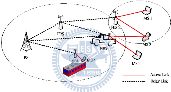
In order to improve the capacity and extend coverage range in 802.16e, IEEE 802.16j task group aims to design a minimal set of function enhancement and extension for mobile multi-hop relay capability. IEEE 802.16 MMR network is that RSs help BS communicate with those MSs that are either too far away from the BS or placed in an area where direct communication with BS experiences unsatisfactory level of services. IEEE 802.16j intends to support multi-hop relay function which is in a BS and numerous RSs can form the footprint of such 802.16 networks. Therefore, it can be significantly expanded in a highly economical manner. The MMR network communication is shown in Figure 2.1. An access link is between MS and its access RS. A relay link is a wireless link that directly connects an access station, which is at the point of direct access to the network for a given MS or RS, with its attached RS. Furthermore, an access station can be a BS or a RS. MR-BS is a fixed base station connected to the access network. Generally, RSs are categorized into fixed RS (FRS)
installed in a fixed location, nomadic RS (NRS) installed for a temporary duration where events occur and mobile RS (MRS) installed on a vehicle such as buses and trains. RS can be deployed either in planned or unplanned manner based on which access links are offered to MSs. Referring to Figure 2.1, MS2 can be served either by NRS or FRS through one of three unique paths (MR-BS→FRS1→FRS2, MR-BS→FRS1→NRS and MR-BS→NRS). In the next section we concentrate on Mobile RS (MRS), which is mounted on a vehicle, for our network model.
Figure 2.1 IEEE 802.16j Network Topology
2.1.2 Usage Model for MRS on Vehicle
MS devices travel together on a mobile vehicle, such as a bus or a train, in this usage model coverage. A mobile RS (MRS) is mounted on the vehicle and it uses a mobile link to connect to an MMR-BS or an RS. The MRS provides a fixed access link to MS devices riding on the vehicle. In this usage model RSs may enter and exit the network when the vehicle enters or exits the coverage area of the network. They may also enter the network when the vehicle is put into service and exit the network when the vehicle quits from service. For example, the first train begins to run in the
morning and the last train ends to run in the evening. In this model, topologies may include communication paths that traverse two or more hops. An example of a multi-hop topology is the case where the train travels through a tunnel and the mobile RS on the train connects to RSs that are deployed along the tunnel.
In this usage model it is expected that a MRS can provide service directly to a number of MSs that are on the vehicle, or via one or more additional RSs that are also mounted on the vehicle, as in the case of a long train. In this case the other RSs are mobile in the sense that they are moving on the vehicle, but they are fixed relative to each other. Therefore, for different scenarios a station may be able to operate as either a BS or RS and may need to switch roles in response to conditions in the field such as an RS losing connectivity to its upstream RS or MMR-BS.
2.2 Handover Protocols
In this section we state MRS handover which is relevant to our scheme. We simply describe mobile IP and depict fast mobile IPv6 protocol in predictive mode and reactive mode.
2.2.1 MRS Handover
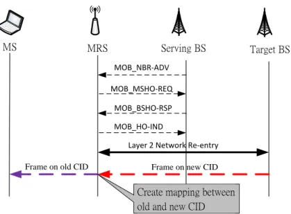
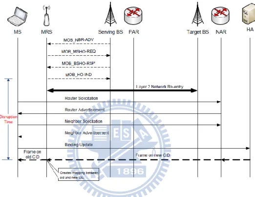
IEEE 802.16j defines a handover process that MS or MRS needs to change the BS for higher signal quality or better QoS when it moves. The handover procedures can be decomposed into three phases: handover preparation, handover decision and initiation, and handover execution. The handover procedures of MRS are illustrated in Figure 2.2.
MRS Serving BS Target BS
MOB_NBR-ADV MOB_MSHO-REQ
MOB_BSHO-RSP MOB_HO-IND
Layer 2 Network Re-entry Frame on new CID Frame on old CID
Create mapping between old and new CID MS
Figure 2.2 Handover procedures of MRS
The handover preparation phase includes network topology advertisement, scanning, and association procedure. During network topology advertisement procedure, a BS needs to broadcast information regarding the network topology through MOB_NBR-ADV message. The purpose of the message is to provide a MRS with the current network identification and information about neighboring BSs, and to facilitate MRS synchronization with neighboring BSs. According to this information, the MRS can make an immediate decision for a future handover. If necessary, a MRS may perform a scanning procedure to find and monitor the suitable neighboring BSs as a target BS. Association procedure is an optional and initial ranging procedure occurred during the scanning interval with respect to one of the neighbor BSs. The handover decision and initiation begin when a MRS needs the handover from serving BS to target BS by sending a MOB_MSHO-REQ message. After receiving MOB_MSHO-REQ message, the serving BS replies MOB_BSHO-RSP message with recommended target BSs to the MRS and sends the MAC addresses and CIDs of the MSs under MRS to these target BSs through the backbone network. Afterward, handover execution occurs. The MRS selects the target BS and sends MOB_HO-IND
message to indicate a handover to the serving BS. After MRS sent MOB_HO-IND message, no packet transfer between the MRS and the serving BS is allowed. Then, MRS performs downlink synchronization, ranging, and network re-entry to the target BS. The target BS assigns new CIDs for MSs and sends it to MRS and then MRS creates mapping between old and new CID for each MS. After handover execution phase, the target BS becomes the serving BS and starts to provide service to the MRS.
2.2.2 Mobile IP
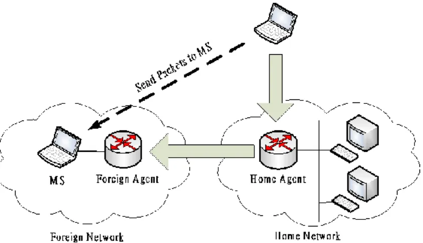
In the current network, both communication ends use IP address. If one side of communication alters the network domain, it will change the IP address, and the link would be interrupted, therefore it must reconnect to the network. We need a technology to help us transform IP address. The technique of mobile IP is developed to solve this problem in IPv4 architecture. With Mobile IP [6], as shown in Figure 2.3, it is unnecessary that a MS needs to change the address and causes interruption with correspondent node due to moving to a different network domain.
Figure 2.3 Mobile IP
When the MS moves to other network domain, it will obtain a care of address (CoA) from the foreign agent. Then, it may have a registration to link between HA and CoA. The packets delivered to HA in local network is sent to home agent and then transferred to MS through the relation of HA and CoA. Through the CoA register technique, MS still can use HA to receive data with correspondent node even though it is not in home network.
2.2.3 Fast Mobile IPv6
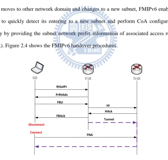
Fast Mobile IPv6 (FMIPv6) [7] is defined to reduce the handover latency for the real-time traffic by movement detection and address configuration procedures. When MS moves to other network domain and changes to a new subnet, FMIPv6 enables a MS to quickly detect its entering to a new subnet and perform CoA configuration early by providing the subnet network prefix information of associated access router (AR). Figure 2.4 shows the FMIPv6 handover procedures.
NAR PAR MS RtSolPr PrRtAdv FBU HI HAck FBAck FNA Tunnel Disconnect Connect
After discovering a new neighbor BS, MS may perform scanning in order to determine the BSs that are available. Then, it selects one of the candidate BSs and obtains a new subnet prefix of the target BS by exchanging the RtSolPr message and PrRtAdv messages with previous AR (PAR). Upon receiving PrRtAdv message, the MS configures its CoA based on the subnet prefix obtained from the message.
When MS decides an impending handover, it notifies the router that there is a binding between previous CoA at the current subnet and new CoA at the target subnet by sending a FBU message to the PAR. Afterward, the PAR sends HI message to the new AR (NAR) for CoA confirmation procedure. After NAR receives HI message, it executes the CoA confirmation, duplicate address detection (DAD) procedure, and replies HAck message to the PAR. At the same time, the tunnel between the previous CoA of MS and its new CoA at the NAR is established.
The NAR receives the tunneled packets and stores them in a buffer until it receives FNA message from the MS. Then, it delivers the buffered packets to the MS. The FNA message is sent after the MS conducts handover to the target BS and performs the network re-entry procedure. On receiving HAck message, PAR sends FBAck message to the MS. If the MS receives this message before its handover and sends MOB_HO-IND message as a final indication of handover, the predictive mode of FMIPv6 is enabled. The predictive FMIPv6 makes the MS to move to the new subnet and receive packets from the NAR quickly.
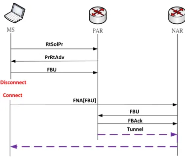
However, if the MS does not receive FBAck message before it is forced to move to the new subnet, reactive mode will occur. In reactive mode, the MS has to wait for packet rerouting to be executed then it can receive packets from the NAR. Figure 2.5 shows the FMIPv6 in reactive mode.
Figure 2.5 FMIPv6 in reactive mode
2.3 Authentication Mechanism
In this section we describe the authentication mechanism of IEEE 802.16. Section 2.3.1 introduces authentication architectures of client and backhaul. Section 2.3.2 states EAP-TLS authentication procedures. Section 2.3.3 describes the derivation of MSK, PMK, and AK in EAP-TLS method.
2.3.1 Authentication architecture
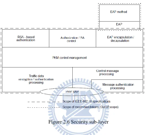
IEEE 802.16e defines security sub-layer to supply the service of privacy, authentication and confidentiality for security of MS in wireless communication. The security architecture platform and privacy key management protocol (PKM) in security sub-layer is shown in Figure 2.6 [2]. There are some different authentication mechanisms on PKM platform. They allow BS and MS to perform single or double authentication. IEEE 802.16 provides two authentication mechanisms, RSA and EAP,
NAR PAR MS RtSolPr PrRtAdv FBU FNA[FBU] Tunnel Disconnect Connect FBU FBAck
which are algorithms for public-key cryptography. The purpose of PKM is to assist MS and BS in generating a shared secret key, i.e. authentication key (AK). And they use the AK to protect the traffic encryption key (TEK) requested for data encryption.
Figure 2.6 Security sub-layer
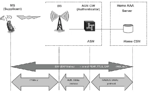
Private key management provides a secure key exchange mechanism. It also supports periodic authentication and key update. To improve and correct the leak of security in PKMv1, PKMv2 is proposed in IEEE 802.16e. As shown in Figure 2.7, MS is a supplicant that will enable the authentication procedures and transmit authentication packets through EAP mode in PKMv2. EAP protocol is generally constructed on AAA Server for storage of authentication information. A BS receiving the authentication packets only needs to relay the packets to authenticator which is put with ASN gateway. Then, the authenticator sends the packets to AAA through RADIUS. And AAA will check whether the supplicant is a legal user or not. The MS can use the WiMAX after AAA certificates it.
Figure 2.7 WiMAX authentication architecture
2.3.2 EAP-TLS
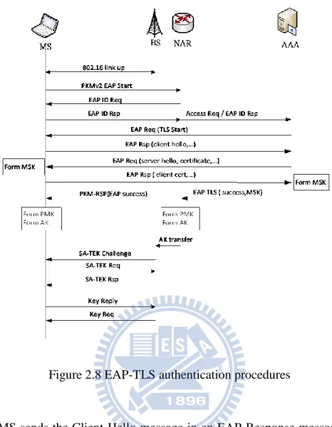
EAP provides a standard mechanism for supporting various authentication methods over wired and wireless networks. EAP-TLS is an EAP-Method defined in RFC 2716 [8]. It uses a certificate to authenticate, in other words, a MS must acquire a certificate from Certification Authority in the network before it uses the EAP-TLS authentication service. The complete authentication procedures are described as follows and Figure 2.8 illustrates these procedures.
1. When a MS links up with BS, the MS sends EAP-Start message to request EAP-TLS authentication.
2. The NAR sends an EAP-Request message to MS for requesting MS’s EAP-identity. The MS answers with an EAP-Response message including its identity. Then, the NAR relays this information to AAA.
3. AAA responses TLS-Start message in an EAP-Request message and the TLS-Handshake begins.
Figure 2.8 EAP-TLS authentication procedures
4. The MS sends the Client-Hello message in an EAP-Response message to AAA. The Client-Hello message includes a random number that guarantees the freshness of the resulting keys to MS.
5. AAA answers with an EAP-Request message including the TLS messages (Server-Hello, Server-Certificate, …). On receipt of these messages, the MS generates a MSK.
6. The MS sends an EAP-Response message including the TLS messages (Client-Certificate, ...). And then AAA generates the MSK using the same method as MS.
7. The EAP-TLS protocol ends with an EAP-Success message sent from AAA to MS. AAA transfers the MSK to ASN through RADIUS. According to the
algorithm defined in IEEE 802.16e, MS and AAA compute the PMK by using the MSK. And then they compute the AK by using PMK. Then, the ASN transmits the AK and relevant parameters to BS.
8. If the BS obtains the AK, it will send SA-TEK Challenge message including authentication information, such as X.509 certificate, to SS. Then, MS responses authorization request message to BS. The BS certifies the identity of MS and then sends authorization reply message including encrypted AK. Upon receiving the encrypted AK, the MS decrypts the AK.
9. After performing PKMv2 three-way-handshake protocol to confirm the AK, MS and BS can use the AK synchronously. The MS has Traffic Encryption Key (TEK) exchange with BS each time for security association. First the MS sends key-request message to BS. The BS certifies HMAC-Digest by SHA1 algorithm [9] and generates TEK. Then, it encrypts the TEK by Key Encryption Key (KEK) generated from AK and responses key-reply message to MS. On receiving the message, MS also certifies HMAC-Digest by SHA1 algorithm and then decrypts the TEK by Key Encryption Key (KEK) generated from AK
2.3.3 Key Derivation
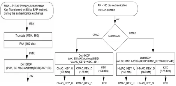
Figure 2.9 [2] shows the key generation and evolution processes. After EAP authentication succeeded, MS and AAA generate a 512-bit MSK by using pseudo random function (formula 1). They truncate 160 bit of the MSK and then generate an AK by putting the PMK into key distribution function (formula 2). Traffic Encryption Key (TEK) is derived as a random number. Also, Key Encryption Key (KEK) and HMAC key are generated by AK using formula 3.
Figure 2.9 Key generation and evolution process
MSK=PRF(SecurityParameters.master_secret, "ttls keying material",
SecurityParameters.client_random + SecurityParameters.server_random) (1) AK = Dot16KDF(PMK, SSID || BSID || AKID || PAK || “AK”, 160), (2) HMAC_KEY_U || HMAC_KEY_D || KEK <= Dot16KDF(AK, SSID || BSID ||
“HMAC_KEYS+KEK”, 448). (3)
2.4 Related Works
In this section, we introduce some related works for our thesis. Section 2.4.1 describes the previous work on which our proposed scheme is based. Then in Section 2.4.2, we introduce the related works about pre-authentication.
2.4.1 A Fast Handover Mobility Scheme over 802.16j Moving RS
Mode[5]
According to the previous description, a MS which moves to another BS and changes the subnet must perform link layer and network layer handover procedures. However, the MS detects that it has been moved to a different subnet after the MRS
performed link layer network re-entry on 802.16j. Then, it performs network layer handover procedures, such as Mobile IPv6. Figure 2.10 describes the conventional handover latency and total disruption time for network layer handover on 802.16j and using Mobile IPv6. In this case, the handover disruption time is significant.
Figure 2.10 Conventional handover procedures with Mobile IPv6
Due to the problem described above, we introduce a mobility scheme to improve this problem. It is based on the mobile vehicle usage model over IEEE 802.16j that is compatible with FMIPv6. Link layer handover is performed by MRS while network layer handover is performed by MS in this network model. This scheme proposes that a MRS and a MS using MAC management messages transmission to accomplish link layer and network layer handover procedures are performed concurrently to reduce the service disruption time. The scheme is shown in Figure 2.11.
Figure 2.11 The scheme in predictive mode (left) and reactive mode (right)
The dot lines represent the MAC layer handover procedures and the solid lines represent the network layer handover procedures. A completed description of message transmission is depicted in the next chapter. In the following we introduce the four messages proposed in the related works.
1. A MRS generates the MRS_NBR-ADV message according to the information in MOB_NBR-ADV message and sends to MS as an advertisement of the BS information next to it.
2. After the handover initiation, the MRS notifies MS that the target BS belongs to a different subnet by sending MRS_HO-REQ message.
3. When the MS finishes the CoA confirmation procedure and receives FBAck message, it will send MRS_HO-RSP message to MRS. If some MSs has not sent this message and the MRS needs to execute the handover immediately, it may cause some MSs to perform handover in predictive mode and others to perform
handover in reactive mode.
4. After the MAC layer network re-entry, MRS informs MS that it has linked with target BS and MS can deliver/receive packets to/from NAR.
The author compares this handover scheme to conventional handover and shows the cartogram in Figure 2.12. The handover disruption time is reduced to about 200 ms which is layer 2 network re-entry processing time.
Figure 2.12 Disruption time in proposed scheme and conventional scheme
The handover disruption time is the major impact to communications quality or QoS. Therefore, we try to reduce the network re-entry processing time by pre-authentication scheme to improve the previous scheme. Next we introduce some related works about pre-authentication mechanism.
2.4.2 Pre-authentication Mechanism
Recently, Kassab et al. proposed a fast pre-authentication scheme [10] for IEEE 802.11 networks based on proactive key distribution. This scheme reduces the
0 200 400 600 800 1000 1200 1400
Conventional Scheme Scheme of [5]
handover latency by reducing the steps of EAP-TLS and computing necessary key material between MSs and BSs in advance. For IEEE 802.16e, Sun et al. proposed a Secure and fast handover scheme [11]. Due to flexibility and security, the proposed scheme is combined with the Public Key Infrastructure. It provides a secure and fast re-authentication procedure during macro-handover, which means a MS moving from one ASN to another ASN can still be authenticated since two ASN gateways are in the same CSN. In the future, integrated WiFi and WiMAX network has great potential due to the high data transport capacity of WiFi and the wider coverage of WiMAX. Hou et al. proposed a pre-authentication architecture [12] based on EAP-TLS protocol. The authentication delay can be significantly reduced when a MS roams between WiFi and WiMAX.
Chapter 3 Proposed Scheme
The proposed scheme and its corresponding MAC management messages to reduce the system disruption time are described in this chapter. Section 3.1 and Section 3.2 present a network model and the new MAC management messages used in the proposed scheme respectively. Section 3.3 describes the procedure of our proposed pre-authentication scheme.
3.1 Network Model
We propose a scheme based on the network model of [5], which is IEEE 802.16j vehicle usage model compatible with FMIPv6. In this model, a MRS can be mounted on mobile vehicles, such as a bus or a train, with several MS which are regarded as mobile devices used by passengers. The network model is shown in Figure 3.1. The MSs connect to network through MRS on the vehicle and move together with MRS, which links to the nearby BS, and the BS contacts with ISP through ASN.
While a vehicle is moving, communication signals between serving BS and MRS which is on the vehicle will drop off. If the MRS moves from the serving BS to target BS belonging to a different subnet, all of MSs on the vehicle have to perform network layer handover procedures from PAR to NAR. On the other hand, the MRS performs MAC layer handover procedures from serving BS to target BS. Different from FMIPv6 that event trigger is used to communicate between MAC layer and network layer in a protocol stack, MAC control messages defined in [5] are transmitted between MRS and MS. Therefore, MAC layer handover procedures on MRS and network layer handover procedures on MSs can be performed concurrently to reduce the service disruption time.
For security concern, a MS will perform full authentication when it first time joins the mobile multi-hop relay network. After performing full authentication, the MS will build mutual trust with MRS. Thus, it is unnecessary to perform re-authentication procedures with MRS when the MS moves together with MRS to another BS. As a result, only the MRS needs to perform re-authentication procedures with target BS to keep security in this network model.
In the previous scheme, the disruption time is reduced by concurrently performing network layer and MAC layer handover procedures. However, the disruption time in previous scheme still remains about 200ms, which is caused by layer 2 network re-entry. In our proposed scheme, re-authentication procedures can be performed between MRS and AAA before a MS links with target BS. Therefore, we improve the layer 2 network re-entry latency and further reduce disruption time.
3.2 MAC Management Messages
are new messages; others are derived by merging two of messages defined in other standard for our new scheme.
(1) MOB_MSHO-REQ / PKMv2 EAP Start message
MS initiated handover may proceed with a notification to the BS through the MOB_MSHO-REQ message. (Including a list of possible target BSs) In the message, a MS uses the known network topology information to choose one or more BS as target BS. It transmits the relevant parameter of transmission quality to the serving BS. And acknowledgement of such message with MOB_BSHO-RSP message is required. In our network model, because only the MRS needs to perform the MAC layer handover procedures, MOB_MSHO-REQ message is sent from MRS to the serving BS. The message format is shown in Table 3.1 [2].
In the conventional scheme, the MRS will send PKMv2 EAP Start message to target BS when it performs layer 2 network re-entry procedures. The message is used to request to process re-authentication procedures for handover. The format is shown in Table 3.2. There is no attributes in the message. It only has two components, management message type and PKM message code, and the size of each is 8 bits.
Table 3.2 PKMv2 EAP Start message format
Syntax Length Value
PKM-REQ_Message_Format() { - -
Management Message Type 8 bit Management Message Type = 9 PKM Message Code 8 bit PKM Message Code = 17
} - -
In our proposed scheme, we merge MOB_MSHO-REQ message and PKMv2 EAP Start message and transmit them together. When a MRS decides to change the serving BS, it will send MOB_MSHO-REQ message to inform the current BS. In our scheme, we send PKMv2 EAP Start message for re-authentication together with MOB_MSHO-REQ message. Therefore, the MRS will perform the EAP-TLS mutual authentication in advance.
TLV encoded information at the end of MOB_MSHO-REQ message is used to add a tag to each transmitted parameter in MAC management messages. It is also used for configuration, definition of parameters like software updates, hardware version, Vendor ID, etc. A TLV encoding consists of three fields: Type, Length, and Value. We append new TLV encoded information in MOB_MSHO-REQ message. The format is shown in Table 3.3. The type of TLV encoding is a reserved type number. The length of TLV encoding is 16 bits, 8 bits of management message type
and 8 bits of PKM message code. The value of TLV encoding is 9 and 17.
Table 3.3 The TLV encoded format for PKMv2 EAP Start
(2) HI / MSK message
In FMIPv6, after a MS which is still connected to the PAR obtains a new CoA, the PAR will validate the new CoA of MS and initiate the process of establishing a bidirectional tunnel between the PAR and the NAR by sending a Handover Initiate (HI) message to the NAR. The message format is shown in Table 3.4. Then, the NAR verifies whether the new CoA can be used on the link of NAR or not. In response to the HI message, the NAR sends Handover Acknowledge (HACK) message to PAR.
Table 3.4 HI message format
In our proposed scheme, we perform pre-authentication procedures through PAR instead of NAR. The AAA generates the MSK, and it transmits the key to PAR. We put the key in HI message so that NAR will obtain the MSK when PAR transmits HI message to NAR. Then, NAR can generate PMK and AK for three way handshake. The message format is shown in Table 3.5. We add a new flag named K in reserved
Name Type Length Value
PKMv2 EAP Start
1 16 Management message type=9 , PKM Message Code =17
Type Code Checksum
Subtype S U Reserved Identifier Options‧‧‧
entry. When K is 0, there is no MSK in the HI message. On the other hand, when K is 1, the MSK is attached in option entry of HI message.
Table 3.5 The HI message format which includes MSK
(3) AK_REQ message, MSK_REQ message, and MSK_RSP message
On the condition that NAR cannot obtain MSK by HI message in reactive mode of our proposed scheme, we create three messages for the NAR to get the AK. When the target BS receives HO_Confirm message, it will confirm whether it has received the AK or not. If not, the target BS will request AK from NAR by sending AK_REQ message. Then, the NAR requests the MSK by sending MSK_REQ message to PAR. The PAR will respond the MSK by sending the MSK_RSP message to NAR. Finally, the NAR uses the MSK to generate the AK and transmits to target BS.
3.3 Main Scheme
In this section, we discuss our proposed mobility scheme on 802.16j network for both predictive and reactive mode. We assumed that the handover scenario is same as the network model presented in Section 3.1. To simplify the description, we discuss only one MS attached to the MRS. Actually in our scheme it makes no difference whether there is more than one MS or not. Section 3.3.1 and Section 3.3.2 depict the proposed scheme in the predictive mode and in the reactive mode, respectively.
Type Code Checksum
Subtype S U K Reserved Identifier
3.3.1 Predictive Mode
The handover procedures in predictive mode are described as follows. Figure 3.2 illustrates these procedures.
MRS Serving BS PAR Target BS NAR AAA MS
MOB_NBR-ADV MRS_NBR-ADV
RtSolP PrRtAdv
MOB_MSHO-REQ [PKMv2 EAP Start]
MOB_BSHO-RSP MRS_HO-REQ FBU HI [MSK] HAck FBAck MRS_HO-RSP MOB_HO-IND MRS_HO-CLT FNA Tunnel Mutual Authentication (EAP-TLS)
DL Sync Parameters and Ranging SA-TEK 3-way handshake
Key Exchange
Network Re-entry
HO-Conform PKMv2 EAP Start
Generate PMK and AK and transmit AK to target BS Generate PMK and AK Link Layer Handover Messages Network Layer Handover Messages Generate MSK Generate MSK and send it to PAR
Figure 3.2 The proposed scheme in predictive mode
1. The serving BS broadcasts MOB_NBR-ADV message periodically.
2. MRS generates MRS_NBR-ADV message according to the information in MOB_NBR-ADV message and sends it to MS.
3. When a new BS is detected, the MS requests the new subnet prefix of the target BS by exchanging RtSolPr and PrRtAdv messages with the PAR.
MOB_MSHO-REQ message which includes PKMv2 EAP Start information to the serving BS. The serving BS sends the PKMv2 EAP Start message to PAR, and then EAP-TLS mutual authentication procedures are communicating between MRS and AAA through the PAR. After that, both MS and AAA generate the MSK. Next, the MS generates the PMK and AK, and AAA sends the MSK to PAR.
5. On receiving MOB_MSHO-REQ message from the MRS, the serving BS can response the MOB_BSHO-REQ message to MRS as a handover initiation. 6. MRS sends MRS_HO-REQ to notify MS that there is an impending handover to
the target BS that belongs to a different subnet.
7. On reception of MRS_HO-REQ message, the MS sends FBU message providing the CoA configured to the PAR. On receiving this message, the HI message including the MSK is sent from PAR to NAR. Then, NAR can generate the PMK and AK based on the MSK.
8. After NAR transmits HAck message to PAR, a tunnel is established between the current CoA and the new CoA. Thus, the packets can be forwarded to the new CoA. During this time, the NAR confirms that the new CoA is unique in the new subnet by performing DAD process. After the tunnel is established, the PAR sends FBAck message to MS.
9. After MS receives the FBAck massage, it sends MRS_HO-RSP message to notify MRS that MS has finished the CoA confirmation procedure.
10. The MRS receives MRS_HO-RSP message before its handover and sends MOB_HO-IND message as a final decision of handover to serving BS. Then, the serving BS notify the target BS. Afterwards it operates in predictive mode in the new link.
exchange are performed between MS and target BS.
12. When MRS finishes network re-entry procedure, it sends MRS_HO-CLT message to MS.
13. On receiving MRS_HO-CLT message, the MS sends FNA message to the NAR. 14. When NAR receives the FNA from the MS, it delivers the buffered packets to the
MS.
3.3.2 Reactive Mode
This section describes the handover procedures in reactive mode. Figure 3.3 shows the procedures.
MRS Serving BS PAR Target BS NAR AAA MS
MOB_NBR-ADV MRS_NBR-ADV
RtSolP PrRtAdv
MOB_MSHO-REQ [PKMv2 EAP Start]
MOB_BSHO-RSP MRS_HO-REQ FBU MOB_HO-IND MRS_HO-CLT FNA [FBU] Tunnel Mutual Authentication (EAP-TLS)
DL Sync Parameters and Ranging SA-TEK 3-way handshake
Key Exchange Network Re-entry HO-Conform PKMv2 EAP Start FBU FBAck Request AK from PAR through NAR Generate PMK and AK Link Layer Handover Messages Network Layer Handover Messages Generate MSK Generate MSK
and send it to PAR
Figure 3.3 Proposed schemes in reactive mode 1. ~ 6. These are same as the procedures in predictive mode.
but MS does not receive FBAck message before MRS sends MOB_HO-IND message as a final indication of handover. And then the serving BS notify the target BS. Afterwards it operates in reactive mode in the new link.
8. When the target BS receives HO-Confirm message, it acquires the AK from NAR which demands the MSK from PAR and generates the PMK and AK. After synchronization and ranging, PKMv2 three-way handshake and key exchange are performed between MS and target BS.
9. When MRS finishes network re-entry procedure, it sends MRS_HO-CLT message to MS.
10. Upon receiving MRS_HO-CLT message, the MS sends FNA message to the NAR, with an encapsulated FBU message.
11. Upon receiving the FNA message, the NAR verifies the availability of the new CoA by performing DAD and forwards the inner FBU message to PAR to establish a packet tunnel.
12. After PAR sends an FBAck message to the NAR as a reply to the FBU message, the PAR starts to tunnel the packets from the old CoA to the new CoA.
Chapter 4 Analysis and Simulation
In this chapter, we provide experimental analysis and simulation of the proposed scheme. Section 4.1 defines some parameters and analyzes the handover latency in the conventional handover scheme, previous scheme described in related work and our proposed pre-authentication scheme. Then, we present the statistical graphs for our analysis. Section 4.2 provides the simulation environment and result of the simulation.
4.1 Numerical Analysis
Regarding required parameters for numerical analysis, there are some reasonable assumptions in our model. Some of them are set in [5]. We design an experiment to measure the SHA1 algorithm processing time used in key derivation and certificate of EAP-TLS authentication on Andes Core. And we calculate the average time by executing 1 million times and get a result of 6.4 milliseconds. Regarding the message transmission time, an experiment designed in the related work [5] measures the processing time of MAC management message. According to the result, average processing time is about 10−3 ms. In IEEE 802.16, message transmission time is based on a frame defined with duration 5 milliseconds. Since the message processing time is much less than the frame duration, the message transmission delay between the network nodes in WiMAX MAC layer is at least one-frame duration long.
Table 4.1 shows the parameters for numerical analysis. Layer 2 network re-entry is divided into several components, which include ranging, SBC, authentication, registration and PSX. As described in Section 2.3.2, the authentication procedures can be also divided into EAP-TLS mutual authentication, 3-way handshake, and key exchange. The SHA1 algorithm is used in AK derivation, two KEKs derivation and
two HMAC certificates.
Table 4.1 Parameters for analysis
Parameter Description
Tframe Frame duration of IEEE 802.16j
TL2_entry Latency of IEEE 802.16j network re-entry procedure
Thop Latency of every routing hop in wired backbone network
Tdad Latency of DAD procedure
Tbs_ar Transmission delay between BS and AR
Npar_nar Number of hop between NAR and PAR
Nnar_ha Number of hop between NAR and HA
Npar_ha Number of hop between PAR and HA
Trng Latency of ranging
Tsbc Latency of SBC
Teap_tls Latency of EAP-TLS procedures
T3_way Latency of 3-way-handshake and key exchange
Treg Latency of registration
Tpsx Latency of PSX
Tsha1 Latency of SHA1 algorithm
Handover latency is defined as the elapsed time from the time that a MS starts to process handover till the moment it can deliver and receive packets through the NAR. In our scheme, the handover process starts when the serving BS sends a MOB_NBR-ADV message. The message transmission delay between serving BS and MRS is Tframe which is same as our previous assumption, and just as MRS and MS.
The overall handover latency of conventional handover, the scheme of [5] and the proposed scheme in predictive mode and reactive mode can be expressed as follows.
(1) Conventional handover
16𝑇𝑓𝑟𝑎𝑚𝑒 + 6𝑇𝑏𝑠_𝑎𝑟 + 2 × (N𝑛𝑎𝑟_ℎ𝑎 + 1)× 𝑇ℎ𝑜𝑝 + 𝑇𝑑𝑎𝑑 + 𝑇𝐿2_𝑒𝑛𝑡𝑟𝑦
(2) The scheme of [5] in predictive mode
20𝑇𝑓𝑟𝑎𝑚𝑒 + 6𝑇𝑏𝑠_𝑎𝑟 + 2 × (N𝑝𝑎𝑟_𝑛𝑎𝑟 + 1)× 𝑇ℎ𝑜𝑝 + 𝑇𝑑𝑎𝑑 + 𝑇𝐿2_𝑒𝑛𝑡𝑟𝑦
(3) The scheme of [5] in reactive mode
17𝑇𝑓𝑟𝑎𝑚𝑒 + 5𝑇𝑏𝑠_𝑎𝑟 + 2 × (N𝑝𝑎𝑟_𝑛𝑎𝑟 + 1)× 𝑇ℎ𝑜𝑝 + 𝑇𝑑𝑎𝑑 + 𝑇𝐿2_𝑒𝑛𝑡𝑟𝑦
(4) Proposed scheme in predictive mode
19𝑇𝑓𝑟𝑎𝑚𝑒 + 6𝑇𝑏𝑠_𝑎𝑟 + 2 × (N𝑝𝑎𝑟_𝑛𝑎𝑟 + 1)× 𝑇ℎ𝑜𝑝 + 𝑇𝑑𝑎𝑑 + 𝑇𝐿2_𝑒𝑛𝑡𝑟𝑦
(5) Proposed scheme in reactive mode
16𝑇𝑓𝑟𝑎𝑚𝑒 + 6𝑇𝑏𝑠_𝑎𝑟 + 4 × (N𝑝𝑎𝑟_𝑛𝑎𝑟 + 1)× 𝑇ℎ𝑜𝑝 + 𝑇𝑑𝑎𝑑 + 𝑇𝐿2_𝑒𝑛𝑡𝑟𝑦
For the requirement of analysis, the equation of layer 2 network re-entry latency would be expressed as follows.
𝑇𝐿2_𝑒𝑛𝑡𝑟𝑦 = 𝑇rng + 𝑇sbc +𝑇eap_tls + 𝑇3_way + 𝑇reg + 𝑇psx + 5𝑇sha1
Disruption time is defined as the elapsed time between MS receiving the last packet from PAR after MRS sending MOB_HO-IND message and MS receiving the first packet from NAR. The disruption time of conventional handover, the scheme of [5] and proposed scheme in predictive mode and reactive mode can be expressed as follows.
(6) Conventional handover
(7) The scheme of [5] in predictive mode 6𝑇𝑓𝑟𝑎𝑚𝑒 + 2𝑇𝑏𝑠_𝑎𝑟 + 𝑇𝐿2_𝑒𝑛𝑡𝑟𝑦
(8) The scheme of [5] in reactive mode
6𝑇𝑓𝑟𝑎𝑚𝑒 + 2𝑇𝑏𝑠_𝑎𝑟 + 2 ×(N𝑝𝑎𝑟_𝑛𝑎𝑟 + 1)× 𝑇ℎ𝑜𝑝 + 𝑇𝑑𝑎𝑑 + 𝑇𝐿2_𝑒𝑛𝑡𝑟𝑦
(9) Proposed scheme in predictive mode
6𝑇𝑓𝑟𝑎𝑚𝑒 + 2𝑇𝑏𝑠_𝑎𝑟 + 𝑇rng + 𝑇sbc + 𝑇3_way + 𝑇reg + 𝑇psx + 4𝑇sha1
(10) Proposed scheme in reactive mode
6𝑇𝑓𝑟𝑎𝑚𝑒 + 4𝑇𝑏𝑠_𝑎𝑟 + 4 ×(N𝑝𝑎𝑟_𝑛𝑎𝑟 + 1)× 𝑇ℎ𝑜𝑝 + 𝑇𝑑𝑎𝑑 + 𝑇rng + 𝑇sbc + 𝑇3_way + 𝑇reg
+ 𝑇psx + 4𝑇sha1
Then, we present the results based on the previous analysis. The parameters used in numerical analysis are shown in Table 4.2.
Table 4.2 Parameters for evaluation
Parameter Tframe Thop Tdad Tbs_ar Npar_nar Npar_ha Nnar_ha
Value 5 ms 0.5 ms 1 s 1 ms 2 hops n hops m hops
Using the parameters above, we can obtain other parameters which are shown in Table 4.3 and the total sum of layer 2 network re-entry latency is given as in the following equation.
Table 4.3 Parameters for evaluation
Parameter Trng Tsbc Teap_tls T3_way Treg Tpsx Tsha1
𝑇𝐿2_𝑒𝑛𝑡𝑟𝑦 = 𝑇rng + 𝑇sbc +𝑇eap_tls + 𝑇3_way + 𝑇reg + 𝑇psx + 5𝑇sha1 = 174 + 3n ms
Handover latency and disruption time in both modes of the proposed scheme and scheme of [5] and in conventional scheme are shown in Figure 4.1. Both numbers of hops (n) between PAR and Home Agent (HA) and NAR and HA are also set to 2. We can find clearly that the handover latency of proposed scheme is a little longer than conventional scheme because it has additional preparation process in our scheme. However, the disruption time of [5] scheme in predictive mode is much lower than that in conventional scheme because the scheme performs CoA confirmation early in predictive mode. And our disruption time of proposed scheme in both modes is lower than that in scheme of [5] because the CoA confirmation in predictive mode and EAP-TLS mutual authentication procedures in both two modes are performed before a MS links with target BS.
.
Figure 4.1 Handover latency and disruption time
The pre-authentication procedures are performed through PAR in our scheme and the authentication procedures are performed through NAR in scheme of [5], so
0 200 400 600 800 1000 1200 1400 Handover Latency Disruption Time
both distances between PAR and AAA and NAR and AAA will affect our improved result. The AAA is located with HA in the Home Internet Service Provider (ISP) network. For disruption time of our proposed scheme, we analyze the improved results from scheme of [5] and conventional handover in different number of hops,
Npar_ha and Nnar_ha. Because the NAR is next to the PAR, we assume that both number of
hops between NAR and HA and PAR and HA are the same, that is n = m. We can find that the improved ratio in predictive mode given in the following equations and show them in Figure 4.2.
(1) Compare with conventional handover
Conventional predictive _disruption _time − Proposed predictive _disruption _time
Conventional predictive _disruption _time
=
96.4+4n 1244+4n
(2) Compare with scheme of [5]
5 predictive _disruption _time − Proposed predictive _disruption _time
5 predictive _disruption _time
=
58.4+3n 206+3n
Figure 4.2 Improved ratio of disruption time 0 0.1 0.2 0.3 0.4 0.5 0.6 0.7 0.8 0.9 1 1 3 5 7 9 11 13 15 17 19 21 23 25 27 29 Im p ro ve d R atio
Number of Hops between HA-AR
Conventional Handover Scheme of [5]
In the Figure 4.2, we can observe that in our proposed scheme the total disruption time is reduced about 90% from conventional handover and reduced 30% to 50% from scheme of [5]. As a result, the more number of hops between HA and AR, the higher improved ratio of disruption time.
4.2 Simulation and Results
Our simulation environments for experiment include coding in C++, NS-2 (version 2.33) simulator [13], Seamless and Secure Mobility Module which is designed and developed by the National Institute of Standards and Technology (NIST) [16] and Light WiMAX Simulator (LWX) Module which supports IEEE 802.16 and IEEE 802.16j. LWX provides 802.16 MAC functionalities with QoS, different modulation coding rates, traffic relay supports and several bandwidth allocation algorithms.
We implement the MRS features, the proposed MAC management messages in [5] and our proposed pre-authentication scheme in the NS-2 simulator. The topology considered for simulation as the network model is presented in Figure 3.1, the model consists of a MRS mounted on a vehicle and moving with MS, it moves from serving BS to target BS which belongs to a different IP subnet in the same ISP network. We present some simulation scenarios to analyze the proposed scheme and conventional scheme. Regardless of different simulation scenarios, the general parameters are presented in Table 4.4.
Table 4.4 General parameters
Parameter Value
Channel type WirelessChannel Radio program model TwoRayGround Network interface type WirelessPhy
MAC type LWX
Interface queue type PriQueue
Link layer type LL
Antenna model OmniAntenna Max packet in ifq 50
Routing protocol AODV
Bandwidth allocation algorithm Round Robin for Relay
Frame duration 5 ms
Traffic type UDP/CBR
For these simulations, our proposed scheme shows better handover disruption latency and packet loss rate than the conventional handover for the VoIP service. Table 4.5 presents the traffic information of VoIP and video. To simplify the simulation, the MS only has one service flow connection.
Table 4.5 Traffic information of simulation
Traffic Type VoIP Video
Packet size 200 bytes 100 byte 1500 bytes
Traffic Rate 64 Kbps 16Kbps 1 Mbps Bandwidth Max 80 Kbps 50 Kbps 4 Mbps Min 2 Mbps
We give each packet a sequence number, and we can observe the packet loss occurred by keeping track of packet sequence numbers received by MS. Figure 4.3, 4.4, and 4.5 show the simulation results in conventional handover for VoIP (200 bytes/64 Kbps and 100 bytes/16 Kbps) and video services. For conventional handover, the packets are transmitted from 0 second to 3 second and MOB_HO_IND message is sent at 1.0601 second. The total disruption time is about 1.25 second.
Figure 4.3 Packet loss rate of conventional handover for VoIP (64 Kbps)
Figure 4.4 Packet loss rate of conventional handover for VoIP (16 Kbps) 0 20 40 60 80 100 120 0 0.5 1 1.5 2 2.5 3 3.5 Se q u e n ce N u m b e r Time (s) 0 10 20 30 40 50 60 0 0.5 1 1.5 2 2.5 3 3.5 Se q u e n ce N u m b e r Time (s)
Figure 4.5 Conventional handover for video
A MS cannot receive any packet during handover execution phase. These figures show that the disruption time is much longer than 1 second. The packets are lost during this disruption time because there is no mechanism for buffering, in other words, the packet loss rate is very high.
On the other hand, the simulation results in our proposed scheme for these three scenarios which are same as conventional handover above are shown in Figure 4.6, 4.7, and 4.8. It shows that not only the shorter disruption time due to the fast handover scheme and pre-authentication scheme but also the buffer mechanism for solving the packet lost problem. The CoA confirmation in FMIPv6 and EAP-TLS mutual authentication in layer 2 network re-entry can be performed before the MS links with target BS. The PAR buffers the packets which are forwarded into the tunnel so that the MS can receive packets before the handover procedures are finished. In these demonstrated results, the packet transmission period is the same as that in conventional handover and MOB_HO_IND message is sent at 2.1151 second. The total disruption time is reduced to about 0.15 second for VoIP and video services, and the packet loss rate in our proposed scheme is much lower than that in the conventional scheme. 0 100 200 300 400 500 0 0.5 1 1.5 2 2.5 3 3.5 Se q u e n ce N u m b e r Time (s)
Figure 4.6 Packet loss rate of proposed scheme for VoIP service (64 Kbps)
Figure 4.7 Packet loss rate of proposed scheme for VoIP service (16 Kbps)
Figure 4.8 Packet loss rate of proposed scheme for video service 0 20 40 60 80 100 120 0 0.5 1 1.5 2 2.5 3 3.5 Se q u e n ce N u m b e r Time (s) 0 10 20 30 40 50 60 0 0.5 1 1.5 2 2.5 3 3.5 Se q u e n ce N u m b e r Time (s) 0 100 200 300 400 500 0 0.5 1 1.5 2 2.5 3 3.5 Se q u e n ce N u m b e r Time (s)
Therefore, we conclude the simulation by comparing the disruption time in conventional handover, scheme of [5], and proposed scheme as shown in Figure 4.9. According to the simulation results, the average disruption time for our proposed scheme is reduced about 90% from conventional handover and about 40% from scheme of [5].
Figure 4.9 Disruption time from simulations 0 200 400 600 800 1000 1200 1400
Conventional Scheme of [5] Proposed VoIP (200 bytes/64kbps) VoIP (100 bytes/16kbps) Video
Chapter 5 Conclusions
In IEEE 802.16j, we propose a pre-authentication scheme for MRS based on the scheme of [5], which includes a mobility scheme and corresponding MAC management messages. The mobile vehicle usage model for our proposed scheme is compatible with FMIPv6. We focus on the improvement for layer 2 network re-entry latency, which caused interruption of handover in [5]. The EAP-TLS mutual authentication procedures are performed and AK is generated in advance, so that we can reduce about 90% latency from conventional handover and 30% to 50 % from scheme of [5] in our numerical analysis.
To further evaluate the efficiency of the proposed scheme, we use NS-2 simulator with Seamless and Secure Mobility Module and Light WiMAX Simulator Module. We implement the MRS features and proposed pre-authentication scheme in the simulator. The result shows that our scheme is able to reduce the interruption latency and packet loss rate successfully. For real-time application service such as VoIP and video streaming, the shorter handover disruption latency means a higher quality of experience (QoE). By reducing the service disruption time, the users can experience a better quality.
However, the proposed scheme still has some defective situations which we can improve in the future, these include: no security mechanism for AK transmission between PAR and NAR, and some items in the handover procedures can still be optimized. Moreover, the proposed scheme can be combined with QoS mechanism in IEEE 802.16j standard.
References
[1] IEEE Standard for Local and metropolitan area networks-Part 16: Air Interface
for Fixed Broadband Wireless Access Systems. IEEE Std 802.16-2004.
[2] IEEE Standard for Local and metropolitan area networks-Part 16: Air Interface
for Fixed and Mobile Broadband Wireless Access Systems. IEEE Std
802.16e-2005
[3] IEEE 802.16’s Relay Task Group; http://wirelessman.org/relay/
[4] N. Montavont, T. Noel, Handover management for mobile nodes in IPv6
networks. IEEE Communications Magazine, 2002. 40(8): p. 38-43.
[5] Y. Yeh, A Fast Handover Mobility Scheme over 802.16j Moving RS Mode, Master Thesis, National Chiao Tung University, July 2009.
[6] D. Johnson, C. Perkins, Mobility Support in IPv6, IETF RFC-3775, June 2004.
[7] Y. Han, et al., A Cross-Layering Design for IPv6 Fast Handover Support in an IEEE
802.16e Wireless MAN. IEEE Network, 2007. 21(6): p. 54-62.
[8] B. Aboba, et al., RFC3748-Extensible Authentication Protocol, June 2004, Standard Track.
[9] D. Eastlake, et al., RFC3174 - US Secure Hash Algorithm 1 (SHA1), September 2001, Standard Track.
[10] M Kassab, A Belghith, JM Bonnin and S Sassi, Fast Pre-Authentication Based
on Proactive Key Distribution for 802.11 Infrastructure Networks, In
Proceedings of the 1st ACM workshop on Wireless multimedia networking and performance modeling, pp. 46-53, 2005.
method for 802.16/WiMAX Infrastructure Networks, in Proc. 2007 Annual IEEE
Region 10 Conference, Taipei, pp.1-4.
[12] L. Hou, K. Miao, A pre-authentication architecture in WiFi & WiMAX integrated
system, Communications and Networking in China, Fourth International
Conference, pp.1-5, 2009.
[13] The Network Simulator - ns-2; http://www.isi.edu/nsnam/ns/
[14] Seamless and Secure Handover; http://www.antd.nist.gov/seamlessandsecure/ [15] Light WiMAX Simulator; http://sites.google.com/site/lwxns2/