國
立
交
通
大
學
網路工程研究所
碩
士
論
文
A Qos framework for IEEE 802.11e and IEEE 802.16e
研 究 生:何昌陽
指導教授:趙禧綠 助理教授
一個在 IEEE 802.11e 以及 IEEE 802.16e 的 QoS 架構
A Qos framework for IEEE 802.11e and IEEE 802.16e
研 究 生:何昌陽 Student:Chang-Yang Ho
指導教授:趙禧綠 Advisor:His-Lu Chao
國 立 交 通 大 學
網 路 工 程 研 究 所
碩 士 論 文
A Thesis
Submitted to Institute of Network Engineering
College of Computer Science
National Chiao Tung University
in partial Fulfillment of the Requirements
for the Degree of
Master
in
Computer Science
June 2007
Hsinchu, Taiwan, Republic of China
Abstract
There is no QoS support in IEEE 802.11 wireless networks. As multimedia applications getting popular, the IEEE 802.11e was proposed as a supplementary to provide both QoS and best effort services. In the IEEE 802.11e standard, four access categories for different QoS demands are defined, and each flow has a designate category according to its application type (voice, video or ftp, etc). On the other hand, the IEEE 802.16e standard defines five different service classes for different QoS applications, and each has different QoS parameters. It is possible that the IEEE 802.11e and 802.16e networks coexist in the near future. Therefore, both homogeneous and heterogeneous handoffs may occur simultaneously. In the standards of IEEE 802.11e and IEEE 802.16e, only homogeneous handoff mechanisms are discussed and defined. To deal with heterogeneous handoffs, QoS satisfaction is one major issue. In this thesis, we develop a framework of heterogeneous networks to support QoS. The framework consists of IEEE 802.11e and 802.16e networks and is implemented by using NS-2 simulator. To support QoS continuously, we design and implement QoS parameter mapping function, call admission control (CAC), and scheduling are essential in this framework. From the simulation results, a QoS flow originally generated in the IEEE 802.11e network can be satisfied with at least its minimum requirement, when passing CAC examination to enter an IEEE 802.16e network. In the meantime, other existing flows of the IEEE 802.16e network do not be affected to become unsatisfying.
摘要
在 IEEE 802.11 的環境當中,並沒有提供對不同的服務有不同的品質。而 IEEE 802.11e 的環境當中,提出了根據不同種類的服務來定義了不同的服務類 型以及優先權。另外,在 IEEE 802.16 的環境中,根據服務需求會對應到不同 類型的服務。而在 IEEE 802.16e 的環境中提供支援端點的移動,且對原本提供 的服務類型當中新增加了一個新服務類型。在有了移動性的支援下,就會有了 交遞的情形發生。然後,在這兩種環境當中,雖然都有提到在相同環境當中的 交遞,卻沒有提到在不同環境當中的交遞的情形。在交遞到不同環境時,因為 不同系統有著不同的服務需求參數,必須要能夠提供轉換的方法。本篇論文提 出了一個在 NS2 的 IEEE 802.16e 的模組,實做出在別篇論文所提過的排程方式 以及系統允入控制機制,再加上已經存在的 IEEE 802.11e 模組,以及定義好在 交替時如何對應服務品質參數,來模擬同時有不同環境的交遞,會有怎麼樣的 情形,並分析其結果。致謝
兩年的研究時間,一下子就過去了。從剛開始考上研究所,對新環境感到 陌生,到現在要完成學業,要離開這個地方,感到有些依依不捨。在大學的時 代,能夠研究網路相關的事物一直是我的目標,所以當能進入以網路工程聞名 的交通大學,我感到非常的開心,能夠在這裡研讀我所感興趣的相關領域。 這篇論文的完成,最感謝的就是我的指導教授趙禧綠老師。不管是一開始 找老師的時候,對我說明了相關領域的一些概要,還是後來在研讀別人論文的 時候,所給我的方向指引以及態度的糾正,到最後程式模擬的建議和論文的修 改及提醒,都是讓我能完成這篇論文相當重要的幫助。有了老師的幫忙,在這 兩年的研究路途,讓我在遭遇困難的時候,可以快速的找出問題點並且解決, 讓我有著信心來完成這份研究。而更多虧了老師的耐心,幫助我把這份成果能 更佳的完善。 另外也要感謝實驗室的同學,在壓力龐大的時期,一起的奮鬥和互相鼓 勵,來度過這段時期,且在我迷惑的時候所給我的建議,總是能啟發許多解決 事情的想法。另外也要感謝實驗室的學長姊和學弟妹,在這段相處的時間給我 們帶來了歡樂,也在我們忙碌的時候給予適時的幫助。 最後我要感謝我的家人,沒有我的父母,今天我就沒辦法完成這份論文, 也多虧他們的體諒,讓我沒辦法常常陪他們,可以在研究中衝刺,感謝他們的 大力支持。最後我要感謝所有幫助過我的人、事、物,謝謝。Contents
Abstract... I 摘要... II 致謝...III Contents ...IV List of Figures...VI List of Tables... VIIIChapter 1. Introduction...1
1.1 An overview of the IEEE 802.11e ...2
1.1.1 Enhanced distributed channel access (EDCA) ...2
1.1.2 Association procedure...4
1.2 An overview of the IEEE 802.16e ...4
1.2.1 MAC supports of PHY...5
1.2.2 Network entry and initialization ...6
1.2.3 Service flow management...7
1.2.4 Scheduling services...9
1.3 Related work ...10
1.4 Motivation...12
1.5 Organization...13
Chapter 2. The IEEE 802.16e modules in NS-2 simulator ...14
2.1 The QoS mapping function ...15
2.2.2 CAC and dynamic service process ...19
2.2.3 The queue and scheduler in the MS ...20
Chapter 3. Performance evaluation ...21
3.1 Simulation environment...21
3.2 Simulation results...24
3.2.1 A handoff flow with different type of service ...24
3.2.2 Blocking probability ...42
3.2.3 CAC performance ...43
Chapter 4. ...48
List of Figures
Figure 1-1 The interframe space relationship ...3
Figure 1-2 The queues in a station with the EDCA mode ...4
Figure 1-3 A TDD frame...5
Figure 1-4 The frame in the 802.16e ...6
Figure 1-5 Dynamic service flow overview...7
Figure 1-6 The BS-initiated dynamic service management...8
Figure 1-7 The MS-initiated dynamic service management...8
Figure 1-8 The proposed structure ... 11
Figure 2-1 The NS-2 module in the Tcl part ...14
Figure 2-2 The IEEE 802.16e functions in NS-2 module...15
Figure 3-1 The simulation topology ...21
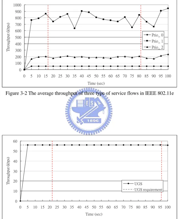
Figure 3-2 The average throughput of three type of service flows in IEEE 802.11e ...26
Figure 3-3 The average throughput of the UGS ...26
Figure 3-4 The average throughput of the rtPS type 1...27
Figure 3-5 The average throughput of the rtPS type 2...27
Figure 3-6 The average throughput of the rtPS type 3...28
Figure 3-7 The average throughput of the ertPS type 1...28
Figure 3-8 The average throughput of the ertPS type 2...29
Figure 3-9 The average throughput of the ertPS type 3...29
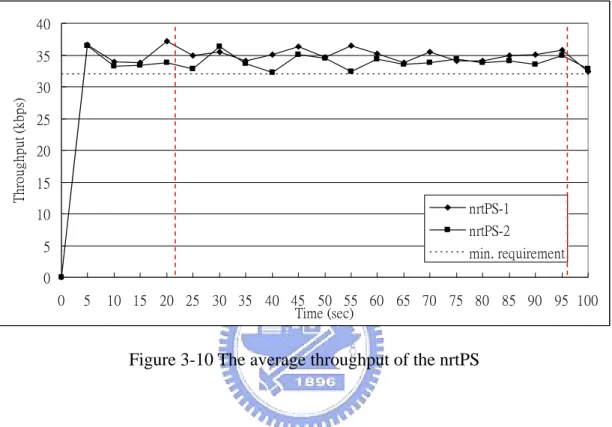
Figure 3-10 The average throughput of the nrtPS ...30
Figure 3-11 The average delay of service flow in IEEE 802.11e ...31
Figure 3-13 The average throughput of the HO voice flow...33
Figure 3-14 The average delay of the HO voice flow...33
Figure 3-15 The average throughput of different service flow in IEEE 802.11e...34
Figure 3-16 The average throughput of the UGS ...35
Figure 3-17 The average throughput of the rtPS type 1...35
Figure 3-18 The average throughput of the rtPS type 2...36
Figure 3-19 The average throughput of the rtPS type 3...36
Figure 3-20 The average throughput of the ertPS type 1...37
Figure 3-21 The average throughput of the ertPS type 2...37
Figure 3-22 The average throughput of the ertPS type 3...38
Figure 3-23 The average throughput of the nrtPS ...38
Figure 3-24 The average delay of the service flow in IEEE 802.11e ...40
Figure 3-25 The average delay of the service flow in 802.16e...40
Figure 3-26 The average throughput of the HO video flow ...41
Figure 3-27 The average delay of the HO video flow ...41
Figure 3-28 The blocking probability in 802.16e with 90% usage of the bandwidth...42
Figure 3-29 The average throughput of the UGS ...43
Figure 3-30 The average throughput of the rtPS ...43
Figure 3-31 The average throughput of the ertPS...44
Figure 3-32 The average throughput of the nrtPS ...44
Figure 3-33 The average delay of the UGS ...46
Figure 3-34 The average delay of the rtPS ...46
Figure 3-35 The average delay of the ertPS...47
List of Tables
Table 1-1. The AC in the IEEE 802.11e...3
Table 2-1 The mapping from IEEE 802.11e to IEEE 802.16e...15
Table 2-2 The mapping from IEEE 802.16e to IEEE 802.11e...16
Table 3-1 simulation parameters ...22
Table 3-2 IEEE 802.11e service flow’s parameter...23
Table 3-3 802.16e service flow’s parameter ...23
Chapter 1. Introduction
The IEEE 802.11 wireless local area network (WLAN) is widely deployed in the world today. The network has two architectures: the infrastructure and the ad hoc mode. In the infrastructure mode, the user will access to the access point (AP) and then connect to the Internet. In the ad hoc mode, every node can transmit the packet to its neighbor nodes without through the AP.
In the WLAN, the medium access control layer (MAC) can perform two functions: distributed coordination function (DCF) and point coordination function (PCF). The DCF is a contention-based mechanism, which utilizes the carrier sense multiple access with collision avoidance (CSMA/CA). The PCF mode is central controlled mechanism, and the AP is response to perform the work. Today the most popular mode in 802.11 is the DCF mode, and we will focus on this function.
But in the IEEE 802.11, the QoS is not introduced. Every flow is with the same probability to content and transmit the packet. So the IEEE 802.11e [1] is proposed to provide the QoS support.
A new network, called the air interface of fixed broadband wireless access (BWA) system, also called Worldwide Interoperability for Microwave Access (WiMax), is developed by the IEEE 802.16 group in the recent year. The system supports two architectures: point-to-multipoint (PMP) and mesh. In PMP mode, the system provides wireless access between the base station (BS) and the mobile subscriber stations (MS). The system can provide a high data rate and long distance transmission range. It can also use high or low frequency bands for different applicability.
The MAC in the system supports the quality of service (QoS) control to the flows. In the IEEE 802.16d [2], there are four types of service flow are defined, but no
mobility is supported. In 2006 the IEEE 802.16e standard [3] was proposed and the network can support the mobility and increase a new service flow type. But the system still not proposes a scheduling scheme and a call admission control (CAC) to perform the QoS control.
With the mobility, the user can move to anywhere, and may need to handoff to the other networks. But in the IEEE 802.11e and IEEE 802.16e, the QoS control and the parameters are different, so we proposed a QoS mapping function that can map the QoS requirement to the other networks and do the QoS control.
1.1 An overview of the IEEE 802.11e
The IEEE 802.11e introduces some QoS support extensions. The architecture here is the infrastructure mode.
1.1.1 Enhanced distributed channel access (EDCA)
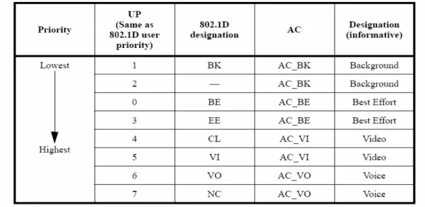
The EDCA is the extension of the DCF in the IEEE 802.11. There are four access categories (AC) are defined to support the QoS in EDCA mode. Table 1-1 shows the AC with the user priority (UP).
Table 1-1. The AC in the IEEE 802.11e
The flows in the EDCA mode with different AC have different arbitration inter frame space (AIFS), minimum and maximum contention window size (CWmax, CWmin). The AIFS is the frame interval that the node shall determine the channel is idle through sense the channel with the interval. The CWmax and CWmin are used to choose the random backoff time. The high priority flows shall have the smaller AIFS and contention window size. Figure 1-1 shows the interframe space relationship.
So the stations in the EDCA mode shall have four service queues and the contention to access the media will be performed between the ACs. Figure 1-2 shows the queues in a station.
Figure 1-2 The queues in a station with the EDCA mode
1.1.2 Association procedure
Before enter into the IEEE 802.11 network, the station need to associate to a AP. The station first shall listen the channel and obtain the parameters of a AP by the beacon or probe message. Then the station shall send a association request to the AP and the AP shall acknowledge the request by a association response. If the response message with a “Successful” value, then the station can enter the network and content the channel to transmit the data packet.
1.2 An overview of the IEEE 802.16e
In this section, we will focus on the PMP mode. In PMP mode, the BS will control the management of the network using the control message.
1.2.1 MAC supports of PHY
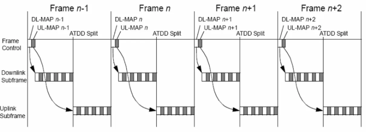
Several duplexing techniques are supported for the IEEE 802.16. Here we focus on the time division duplexing (TDD), the downlink map (DL-MAP) and the uplink map (UL-MAP).
The downlink in the 802.16 is the direction of the transmission from the BS to the MSs. And the uplink in the 802.16 is the direction of the transmission from the MSs to the BS.
In a TDD frame, the downlink and the uplink transmission start at different time. The downlink duration and the uplink duration may be fixed or adaptive. It is controlled by the high layer. In the paper, the transmission duration is fixed. Figure 1-3 shows a TDD frame.
The DL-MAP defines the usage of the downlink intervals. And the UL-MAP defines the allocation start time of the MSs to transmit packet and the uplink allocation for a flow or a MS and the uplink intervals. These maps are generated by the BS and send to the MS at the start of every frame. Figure 1-4 shows the full frame in the IEEE 802.16.
Figure 1-4 The frame in the 802.16e
1.2.2 Network entry and initialization
The IEEE 802.16 shall support a MS enter into the network. The procedure for initialize a MS shows below:
a). Scan downlink channel and establish synchronization with the BS b). Obtain transmit parameters (from the UCD messages)
c). Ranging
d). Negotiate basic capability
e). Authorize MS and perform key exchange f). Registration
g). Establish IP connectivity h). Establish time of day
i). Transfer operational parameters j). Set up connection
The phase e), g), h), i) are optional. The authorization phase shall be performed only the MS and the BS support the authorization policy.
power. The ranging process shall be repeated until the ranging response contain successful notification or the BS abort. After the process, the MS will get the basic and primary management CID.
In the registration phase, the MS is allowed entry into the network and the MS receives the secondary CID. Then the MS will be the managed MS.
After the transfer operational parameters phase or the registration, the MS can start to set up the connection by the dynamic service creation process.
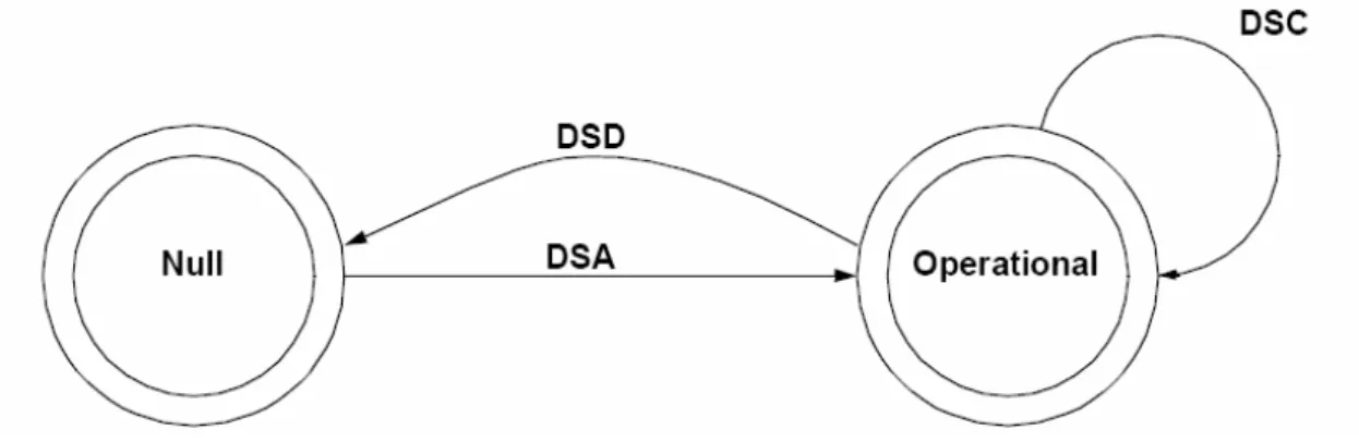
1.2.3 Service flow management
In the 802.16e network, the service flow is managed by the dynamic service message. The service flow may be created, changed and deleted. The dynamic service addition (DSA) message is used to create a new connection. The dynamic service change (DSC) message is used to change the connection’s parameter. And the dynamic service deletion is used to delete the existing connection. Figure 1-5 shows the management.
The dynamic service management can be initialized by the BS or by the MS. The management first will send a request message (DSx-REQ) to start the process. When
receive the request, the receiver will send a response (DSx-RSP) back to the transceiver with the result. After the transceiver receive the response, the transceiver will send the acknowledge (DSx-ACK) to the receiver. Figure 1-6 and 1-7 show the BS-initiated and MS-initiated management process.
Figure 1-6 The BS-initiated dynamic service management
Figure 1-7 The MS-initiated dynamic service management
BS SS DSx-REQ DSx-RSP DSx-ACK DSx-RVD BS SS DSx-REQ DSx-RSP DSx-ACK
1.2.4 Scheduling services
The scheduling services means the service that the scheduler how to handle. Each service has a set of QoS parameters. The parameters are managed by the dynamic service process. There are five scheduling services in the 802.16e.
1.2.4.1 Unsolicited grant service (UGS)
The UGS is designed to support the real time service with fixed generation interval and packet size, such as VoIP. The character of UGS is guaranteed data rate and delay. The parameters for UGS are maximum sustained data rate, maximum latency, tolerated jitter. If present, the minimum reserved data rate will set as the maximum data rate.
1.2.4.2 Real-time polling service (rtPS)
The rtPS is designed to support the real time streaming with variable packet size, such as video. The delay is a little tolerable and the data rate is larger than the UGS. The parameters for the rtPS are maximum sustained data rate, minimum reserved data rate, and maximum latency.
1.2.4.3 Extended real-time polling service (ertPS)
The ertPS is a new proposed scheduling service in the IEEE 802.16e std [2]. This is a scheduling scheme which builds on the efficiency of both UGS and rtPS. The BS provides grants to the MS like the UGS, but the allocation size shall be dynamic. The MS can change the allocation size by sending the control message to the BS. The parameters for the ertPS are maximum sustained data rate, minimum reserved data
rate, maximum latency.
1.2.4.4 Non-real-time polling service (nrtPS)
The nrtPS is for the delay-tolerant data flow with variable packet size. The BS shall provide request opportunity, with a larger interval than the rtPS, and the MS can use the contention request opportunity. The parameters for the nrtPS are maximum sustained data rate, minimum reserved data rate and traffic priority.
1.2.4.5 Best effort (BE)
The BE is for the data flow without the minimum service level requirement. The MS is allowed to use the contention opportunity. The parameters of this service type are maximum sustained data rate and priority.
1.3 Related work
About the handoff in the heterogeneous networks, there are lots of paper are proposed. But in these papers, the QoS relative subjects are little. Most of these papers propose a gateway or router between the heterogeneous networks to help a host to handoff [4]. Using these architectures, a station can handoff quickly or support the network to authenticate the station. In [5], a three-plane QoS frame was proposed. Every plane has individual part of function, but the detail of these parts didn’t illustrate clearly in the paper. In [6], a QoS architecture was proposed to integrate the QoS broker and AAAC system. When a mobile host does the handoff process, the QoS broker will inform the new access router to maintain the QoS requirement of the
Although the topics about the QoS in the heterogeneous networks are many, the topic about the QoS between the IEEE 802.11 and IEEE 802.16 is less. In [7], a QoS architecture was proposed to inter-work the IEEE 802.11e and IEEE 802.16. But the architecture is a new QAP in the IEEE 802.11e and the QAP connects to the IEEE 802.16 networks. The QAP transfers the flow which is originating from the IEEE 802.11e to the IEEE 802.16 parameters. The architecture also propose two kind of mappings: priority mapping and parameters mapping, but the paper didn’t describe how the priority mapping does.
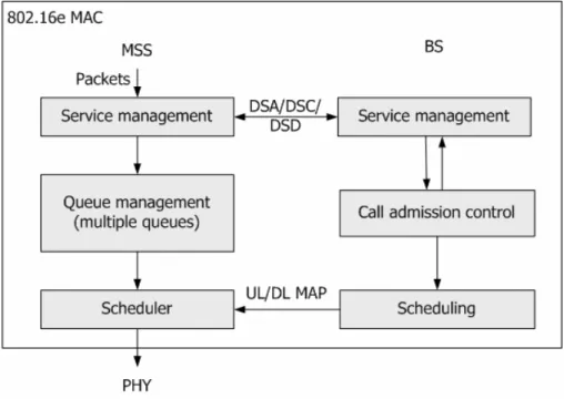
In [2] and [3], the scheduling and call admission control (CAC) are mentioned but didn’t define these two functions clearly. Figure 1-8 shows the IEEE 802.16e structure.
The scheduling is used to schedule the uplink and made the uplink map (UL-MAP) to send to the all MS. The priority-based scheduling is with the order to schedule: UGS, rtPS, ertPS, nrtPS, that is the scheduling will check every flow which is admitted by the CAC with this order and may give the flow a transmit opportunity if the flow needs to transmit the data.
Figure 1-8 The proposed structure
Base station CAC 802.16e MAC Scheduling Mobile host Upper layer Dynamic Service process Link map
The CAC in IEEE 802.16e is response for service flow management. When the BS receives the dynamic service messages, the CAC will check the parameters in the message. If the message is a service flow addition or service flow change message, the CAC will adjust that whether the BS can support the new requirement or not. If the BS can’t support the requirement, CAC will response a message with the reject information back to the MH. Else the CAC will record the new requirement of the connection and response the message with success information and other parameters. And if the message is the service flow deletion message, the CAC will delete the record of the service flow and response a success message. In [8], the system can decide how much resource should be kept for the contention period and the CAC should use this bound to act.
1.4 Motivation
With the mobility is respected in the wireless network and the new wireless networks technology is proposed, the topics about the heterogeneous networks are popular. But in the IEEE 802.11e standard [1] and IEEE 802.16 standard [2], only mention about how a new host enter into the network and the QoS mechanism in the network. But before enter into the heterogeneous networks, the standards do not mention what a user need to do. Because the QoS mechanisms are different in these networks, a mapping function is needed to solve the problem.
The network simulator NS-2 [9] has had IEEE 802.11e module and IEEE 802.16e module today. But there is no any integrated function to simulate the two networks in the same time. And the IEEE 802.16e module doesn’t have the scheduling and CAC functions in the proposed module. So we propose a IEEE 802.16e module in NS-2, and introduce these function to simulate to handoff behavior.
1.5 Organization
The organization of the remaining thesis is as followed. Chapter 2 describes the proposed scheduling and the CAC. Chapter 3 describes our NS-2 modules in detail and Chapter 4 is the performance evaluation. The conclusion is in the chapter 5.
Chapter 2. The IEEE 802.16e modules
in NS-2 simulator
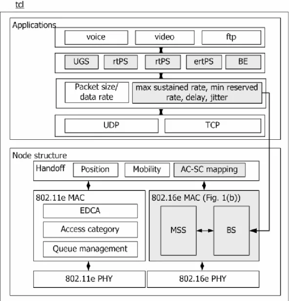
In this chapter, we propose an IEEE 802.16e module in NS-2 simulator [9]. Figure 2-1 and 2-2 are the proposed functions in the NS-2 simulator. The rectangles with broken line are the performed functions we made and the words with red color are the functions that we modify the existing functions in the NS-2 module.
Figure 2-2 The IEEE 802.16e functions in NS-2 module
2.1 The QoS mapping function
The QoS mapping function is used in the tcl part. The tcl part is response for the simulation scenario setting in NS-2. When a handoff is happened, the QoS mapping function shall transform AC of the flows in IEEE 802.11e to the scheduling service type in IEEE 802.16e or the scheduling service type to the AC in IEEE 802.11e.
By [1] and [3], we define the mapping here. Table 2-1 shows the mapping from AC to scheduling service type and Table 2-2 shows the mapping from scheduling service class (SC) to the AC.
Table 2-1 The mapping from IEEE 802.11e to IEEE 802.16e IEEE 802.11e IEEE 802.16e
AC_VO UGS AC_VI rtPS AC_BE nrtPS or BE
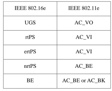
Table 2-2 The mapping from IEEE 802.16e to IEEE 802.11e IEEE 802.16e IEEE 802.11e
UGS AC_VO rtPS AC_VI ertPS AC_VI nrtPS AC_BE BE AC_BE or AC_BK
By [2] and [3], the different ACs and SCs are defined for the different applications. So our mapping function is based on the SC and AC for the same type of application.
In the mapping from IEEE 802.11e to IEEE 802.16e, the AC_BE may map to the nrtPS or BE, is because in [2] the nrtPS can be used for a TCP connection. If the connection needs a minimum QoS requirement, the function will map the connection to the nrtPS flow. And in the mapping from IEEE 802.11e to IEEE 802.16e, the BE can map to the AC_BE or AC_BK, is because these two AC are for the TCP connections. If the connection needs the more requirements, like FTP, the function will map the connection to the AC_BE. Else maps to the AC_BK.
In IEEE 802.16e, when a new connection wants to be set up, the connection’s QoS parameters will send to the BS by the DSA-REQ. So the function need to get the parameters when the MH handoff to the IEEE 802.16e network. The mapping function will ask the upper layer to get these parameters to do the dynamic service process.
2.2 The IEEE 802.16e MAC
2.2.1 Scheduling in BS
In our module, there are two timers for every connection that the scheduling will check these timers when it makes the schedule. The first timer is the minimum requirement timer. It is used to satisfy the minimum requirement of all flows. By the dynamic service message, the BS can get the minimum reserved rate and the packet size, then the BS can calculate a maximum packet inter arrival time, Ti,min−req. If the connection is with variable packet size, the scheduling will use a fixed size to calculate the time, and when the connection receive the opportunity, the connection can fragment or pack the packet in the queue to satisfy the opportunity length L.
) ( min min , L rate i Ti −req+= (1) By using the time to give the transmit opportunity to the connection, the connection must be satisfied with the minimum requirement. The minimum requirement timer will set the value to the Ti,min−req at first and start to count down. When the value of the timer is less than zero, it means that the connection needs to get opportunity. And the scheduling will schedule the connection into the UL-MAP and the timer is reset to the Ti,min−req value.
The other timer is the advanced allocation timer. When the minimum requirement of every connection has been satisfied, the residual resource BWR will be
shared to the connections that the maximum requirement has not been satisfied.
( )
{ } { }( )
( )
{∑
} {∑
}( )
∑
∑
∈ ∈ ∈ ∈ − − − − × = nrtPS i ertPS i rtPS i UGS i residual i rate i rate i rate i rate C BW min min min α (2)minimum reserved rate of the flow. Because UGS only has one data requirement, UGS will not share the residual resource. The ratio of rtPS, ertPS, nrtPS is as below.
( )
( )
(
)
{ } {(
}( )
( )
)
( )
( )
(
)
{ rate} k rate k a b c j rate j rate i rate i rate nrtPS k ertPS j rtPS i : : : : min max min max min max = ∑ − ∑ − ∑ − ∈ ∈ ∈ (3)ratemax(i) is the maximum sustained rate of the connection i. In the same type of the
scheduling service, the connection i can get the advance resource is:
( )
(
(
( )
( )
( )
)
( )
)
{∑ } − − × × + + = ∈ rtPS l max min min max residual ex l rate l rate i rate i rate BW c b a a i BW (4)( )
(
(
( )
( )
( )
( )
)
)
{∑ } − − × × + + = ∈ ertPS l max min min max residual ex l rate l rate j rate j rate BW c b a b j BW (5)( )
(
(
( )
( )
( )
( )
)
)
{∑ } − − × × + + = ∈ rtPS l max min min max residual ex l rate l rate k rate k rate BW c b a c k BW (6) exBW is the advance allocation of the connection in the scheduling service type video. Then the time interval Ti,ex that is used to get the advance opportunity is as bellow.
ex i,ex L BW
T += (7) And the advanced allocation timer will set the value to Ti,ex at first and start to count
down as the minimum requirement timer. While the timer is less than zero, the scheduling will schedule the advance opportunity for the connection and reset the timer.
The scheduling may not schedule all the connections that need the opportunity. The scheduling will schedule all the connections that need to allocate opportunity to transmit data until the frame is full and schedule the not satisfied connections at the next frame.
2.2.2 CAC and dynamic service process
The CAC and the dynamic service process has describe before. The main purpose of CAC is used to guarantee the QoS requirements of the admitted services, and we introduce this to help the scheduling. In our module, we introduce the CAC in [8] and do a little modification. Our CAC is performed by the formula below. If the new connection’s rate can satisfy the formula, the CAC will accept the new connection.
( )
( )
{ } { }( )
{ }( )
( )
{ rate} m C l rate k rate j rate i rate nrtPS m ertPS l rtPS k UGS j × ≤ + + + +∑
∑
∑
∑
∈ ∈ ∈ ∈ α min min min min (8)After the exchange of the service flow message and the response is with success information, the CAC will inform the scheduling to re-calculate the new time interval value for the advance allocation timer.
If the traffic load is heavy, the BS may still have a little resource and a new connection wants to be set up, but the resource is not enough to satisfy the minimum requirement, the connection will be rejected by the BS. At this time, we hope the new connection can reduce its requirement and the reject probability can reduce a little. So we propose a message exchange process to achieve the intent. If a new connection’s request send to the BS, and the CAC find there is no sufficient resource to satisfy the connection and the connection is not a voice flow, the CAC will send the response message with success message to the MH, then send a DSC request (DSC-REQ) to request the SS to reduce the new flow’s minimum requirement. If the SS accept the request, then the BS records the original minimum requirement, and uses the temporary requirement to do the scheduling process. Else if the MH rejects the request, than the BS will send the DSD-REQ to the MH to delete the service flow. After other connections are end and have advance resource, the BS will send a
DSC-REQ to ask the SS to change the minimum requirement to the original requirement first and re-calculate the new time interval value will be done after the message exchange process.
2.2.3 The queue and scheduler in the MS
The MSs need the queue module in IEEE 802.16e is because every flow will get the grant individually, every flow need a independent queue to store the packets. When a new flow wants to be set up, the queue module will receive the message from the up layer and inform the scheduler in the MS to execute the dynamic service process. After the success dynamic service addition process, the queue module will create a new queue for the new flow.
The scheduler in the MS has another function. When receiving a UL-MAP, the scheduler need to check the map that whether there is a grant for the flow in the MS or not. If there are grants for flows, the scheduler will wait to the assignment of the start time and transmit the packet from the queue module.
Chapter 3. Performance evaluation
3.1 Simulation environment
Figure 3-1 shows the topology of the simulation. And in the simulation, the global parameters of the simulation are defined in Table 3-1.
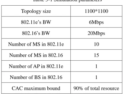
The CAC maximum bound means the CAC will reject a new service flow if the total used resource has exceeded the bound. We set the value is 90% of total resource here due to partial of bandwidth is reserved for management overhead.
Table 3-1 Simulation parameters Topology size 1100*1100 802.11e’s BW 6Mbps 802.16’s BW 20Mbps Number of MS in 802.11e 10 Number of MS in 802.16 15 Number of AP in 802.11e 1 Number of BS in 802.16 1
CAC maximum bound 90% of total resource
The traffic load has defined here by three types:Heavy、Medium、Light. 1. Heavy:Total used BW > 0.7 * Total available BW
2. Medium:0.4 * Total available BW <Total used BW < 0.7 * Total available BW 3. Heavy:Total used BW < 0.4 * Total available BW
The IEEE 802.11e module in NS-2 is from [10]. In the system, the different priority of the service flow has defined the parameters in Table 3-2.
The service flows in IEEE 802.16 are illustrated in Table 3-3. In order to test the scheduling that can apply the sufficient resource to the service flow, the same type of the service flow may have different parameters. When a packet has been generated and the queued time is larger than the maximum latency, the packet will be dropped.
In the IEEE 802.16e, the rtPS and ertPS has three type of service flow with different minimum data rate.
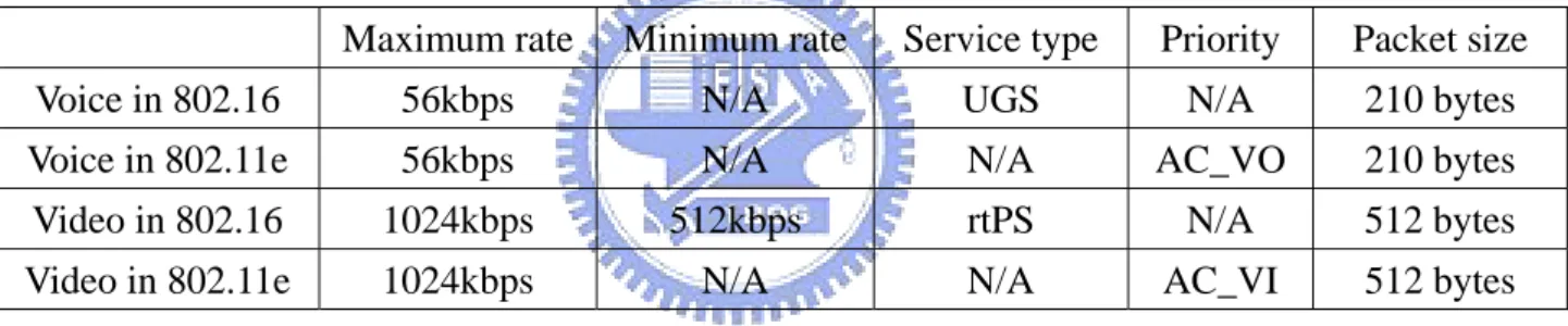
Each MH has two kinds of service flow: voice and video. The parameter mapping of the flow at the MH has defined in Table 3-4.
Table 3-2 IEEE 802.11e service flow’s parameter
Priority Data rate Type Packet Size Max. Latency
1 56kbps Voice 210 bytes 25ms
2 1024kbps Real time video 512 bytes 100ms 3 128kbps、256kbps Non-real time video 512 bytes 200ms
Table 3-3 802.16e service flow’s parameter
Type Max. rate Min. rate Packet Size Max. Latency
UGS 56kbps N/A 210 bytes 25ms
rtPS 1024kbps 128kbps、256kbps、512kbps 512 bytes 100ms ertPS 1024kbps 128kbps、256kbps、512kbps 512 bytes 100ms
nrtPS 128kbps、256kbps 32kbps 512 bytes 200ms
Table 3-4 The mapping parameters of the flow
Maximum rate Minimum rate Service type Priority Packet size Voice in 802.16 56kbps N/A UGS N/A 210 bytes Voice in 802.11e 56kbps N/A N/A AC_VO 210 bytes Video in 802.16 1024kbps 512kbps rtPS N/A 512 bytes Video in 802.11e 1024kbps N/A N/A AC_VI 512 bytes
In our simulation, a flow starts and ends randomly. When a flow is stop, it may restart again after waiting a random time. The flow will ask the BS to give the flow a new CID and the CAC may reject this flow. Every mobile host may have a service flow, and may do the handoff at a random time. If the MH does the handoff, the service flow at the MH will mapping to the new network’s parameters.
The performance metrics include the average throughput Ttype and delay Dtype and
blocking rate in the network. A flow’s average throughput means the total data that the AP (or BS) received during the simulation time:
( ) Time size packet Transmit T N i i type type
∑
= = 1 ,N is the total number of the nodes.
The Delay means the waiting time for a packet to transmit to the AP (BS) when the packet is generated and the average delay time is the average of every packet’s delay: ( ) packets transmit of number Delay D N i i type type
∑
= = 1 , (10) The blocking rate is the percentage of handoff connections which are rejected by the BS to enter the IEEE 802.16e network due to failed CAC checkWe also show the blocking probability here. The blocking probability means the probability when a flow handoff to the IEEE 802.16e network and the CAC in the BS will reject the request of the new flow to put the flow into the scheduler.
3.2 Simulation results
3.2.1 A handoff flow with different type of service
In this simulation, there is only one MH in the simulation and do the handoff during the simulation. The MH may have a voice flow or a video flow. The traffic loads in both IEEE 802.11e and IEEE 802.16e are heavy. The number of flows in IEEE 802.11e is at least ten flows and the number of flows in the IEEE 802.16e is at least sixty flows.
First we show the result when the flow is a voice flow. The average throughput in IEEE 802.11e and the IEEE 802.16e are showed in the below.
The MH is in the IEEE 802.16e first and starts to move. It moves to the IEEE 802.16e at 9.6, 21.8, 27.8, 44, 53.4, 57.9, 76.9, 84.2, 95.6 second and moves to IEEE
802.11e at 8.3, 17, 24.1, 38.8, 48.1, 56.8, 68.6, 81.2, 88.3 second.
The simulation does not have any traffic first and will start to set up every flow at first 7 second.
In IEEE 802.11e, when a voice flow is set up or set down, the voice’s throughput (Prio_ 0) does not have obvious change. The real time video’s throughput (Prio_ 1) has more obvious change, but is not by reason of the handoff voice flow. The really reason is the other video flow’s start or end at that time and the voice connection only need a little resource and the IEEE 802.11e use the contention process to content the resource. The backoff time is randomly selected. So the throughput is not guaranteed. The vertical broken line in Figure 3-2 is the time point that the MH to 802.11e network. We only show the time that the throughput has obvious change.
Figure 3-3 to Figure 3-10 are the average throughput of the different types of services in 802.16e. The vertical dashed lines in the figures are the time points that the MH handoff to the 802.16e network. Although the traffic load is heavy, the network can still satisfy every flow’s minimum QoS requirement and the residual resource can be shared out to the flows that the maximum QoS requirement are not satisfied. The voice connection need very small requirement, so the throughput of other services just a little degradation.
0 100 200 300 400 500 600 700 800 900 1000 0 5 10 15 20 25 30 35 40 45 50 55 60 65 70 75 80 85 90 95 100 Time (sec) T h roughpu t ( kbps ) Prio_ 0 Prio_ 1 Prio_ 2
Figure 3-2 The average throughput of three type of service flows in IEEE 802.11e
0 10 20 30 40 50 60 0 5 10 15 20 25 30 35 40 45 50 55 60 65 70 75 80 85 90 95 100 Time (sec) T hr oughput ( kbps ) UGS UGS requirement
0 50 100 150 200 250 300 350 0 5 10 15 20 25 30 35 40 45 50 55 60 65 70 75 80 85 90 95 100 Time (sec) T hr ou ghput ( kbps ) rtPS-1 min. requirement
Figure 3-4 The average throughput of the rtPS type 1
0 50 100 150 200 250 300 350 400 450 0 5 10 15 20 25 30 35 40 45 50 55 60 65 70 75 80 85 90 95 100 Time (sec) T hr oug hp ut ( kb ps ) rtPS-2 min. requirement
0 100 200 300 400 500 600 700 0 5 10 15 20 25 30 35 40 45 50 55 60 65 70 75 80 85 90 95 100 Time (sec) T hr oughpu t (kbps ) rtPS-3 min. requirement
Figure 3-6 The average throughput of the rtPS type 3
0 50 100 150 200 250 300 350 0 5 10 15 20 25 30 35 40 45 50 55 60 65 70 75 80 85 90 95 100 Time (sec) T h ro u ghp ut (kb ps) ertPS-1 min. requirement
0 50 100 150 200 250 300 350 400 450 500 0 5 10 15 20 25 30 35 40 45 50 55 60 65 70 75 80 85 90 95 100 Time (sec) T hr oug hpu t (k bp s) ertPS-2 min. requirement
Figure 3-8 The average throughput of the ertPS type 2
0 100 200 300 400 500 600 700 0 5 10 15 20 25 30 35 40 45 50 55 60 65 70 75 80 85 90 95 100 Time (sec) T hr ou ghput ( kbps ) ertPS-3 min. requirement
0 5 10 15 20 25 30 35 40 0 5 10 15 20 25 30 35 40 45 50 55 60 65 70 75 80 85 90 95 100 Time (sec) T hr ou gh put ( kbps ) nrtPS-1 nrtPS-2 min. requirement
Figure 3-10 The average throughput of the nrtPS
In Figures 3-11 and 3-12, the average delay in 802.11e is less than that in the 802.16e network. It is because in 802.11e networks, many packets will be dropped after exceeding the retry limit. On the other hand, the packets of the flows in 802.16e network will be queued in the buffer, until the nodes receive the grant from the BS, or queued over the maximum latency time than drop the packet. But in the heavy traffic load environment, the nodes can’t get enough grants to transmit all the packets. So the delay time is almost equal to the maximum latency time.
0 0.005 0.01 0.015 0.02 0.025 0.03 0.035 0 5 10 15 20 25 30 35 40 45 50 55 60 65 70 75 80 85 90 95 100 Time (sec) De la y ( se c) Prio_ 0 Prio_ 1 Prio_ 2
Figure 3-11 The average delay of service flow in IEEE 802.11e
0 0.02 0.04 0.06 0.08 0.1 0.12 0.14 0.16 0 5 10 15 20 25 30 35 40 45 50 55 60 65 70 75 80 85 90 95 100 Time (sec) D el ay (s ec) UGS rtPS ertPS nrtPS
Figures 3-13 and 3-14 are the throughput and delay time of the voice in the MH. Here we can see that when the flow handoff to IEEE 802.16e network or to the IEEE 802.11e network, the effect of the existed flow is not obvious.
The MH is in the IEEE 802.11e network first and starts to move. It moves to the IEEE 802.16e at 14.2, 31.5, 57.8, 66.9, 74.6, 79.7, 96.9 second and moves to IEEE 802.11e at 30.2, 38.5, 61.2, 70.5, 77.6, 86.1 second.
40 44 48 52 56 60 0 5 10 15 20 25 30 35 40 45 50 55 60 65 70 75 80 85 90 95 100 Time (sec) T hr ough put ( kbps ) HO voice Voice in 802.11e Voice in 802.16e
Figure 3-13 The average throughput of the HO voice flow
0 0.001 0.002 0.003 0.004 0.005 0.006 0.007 0.008 0 5 10 15 20 25 30 35 40 45 50 55 60 65 70 75 80 85 90 95 100 Time (sec) D el ay (s ec) HO voice Voice in 802.11e Voice in 802.16e
The other scenario is a MH with a video flow and may handoff to another network. Like the scenario in the before, the vertical broken lines in Figure 3-15 are the handoff time in 802.11e. And the video flows’ effect is not caused by the handoff video flow, is the start or end of other video flows. The voice flows in the IEEE 802.11e are also not affected because these flows have high priority and will select a little backoff time.
From Figure 3-16 to Figure 3-23 are the average throughput in 802.16e. When the MH is at the IEEE 802.16 network, the average throughput of UGS is not affected, but the other services are a little decrease and still satisfy their minimum QoS requirement. But the decrease is more obvious than the scenario before.
0 100 200 300 400 500 600 700 800 900 1000 0 5 10 15 20 25 30 35 40 45 50 55 60 65 70 75 80 85 90 95 100 Time (sec) T hr oughpu t ( kb ps ) Prio_ 0 Prio_ 1 Prio_ 2
0 10 20 30 40 50 60 0 5 10 15 20 25 30 35 40 45 50 55 60 65 70 75 80 85 90 95 100 Time (sec) T hr o ug hp ut ( kb ps ) UGS UGS requirement
Figure 3-16 The average throughput of the UGS
0 50 100 150 200 250 300 350 0 5 10 15 20 25 30 35 40 45 50 55 60 65 70 75 80 85 90 95 100 Time (sec) T hr oughp ut ( kbps ) rtPS-1 min. requirement
0 50 100 150 200 250 300 350 400 450 0 5 10 15 20 25 30 35 40 45 50 55 60 65 70 75 80 85 90 95 100 Time (sec) T hr o ughpu t ( k bps ) rtPS-2 min. requirement
Figure 3-18 The average throughput of the rtPS type 2
0 100 200 300 400 500 600 700 0 5 10 15 20 25 30 35 40 45 50 55 60 65 70 75 80 85 90 95 100 Time (sec) T hr oughp ut ( kbps ) rtPS-3 min. requirement
0 50 100 150 200 250 300 350 0 5 10 15 20 25 30 35 40 45 50 55 60 65 70 75 80 85 90 95 100 Time (sec) T hr o ughp ut ( kbp s) ertPS-1 min. requirement
Figure 3-20 The average throughput of the ertPS type 1
0 50 100 150 200 250 300 350 400 450 500 0 5 10 15 20 25 30 35 40 45 50 55 60 65 70 75 80 85 90 95 100 Time (sec) T hr oug hput ( kbps ) ertPS-2 min. requirement
0 100 200 300 400 500 600 700 0 5 10 15 20 25 30 35 40 45 50 55 60 65 70 75 80 85 90 95 100 Time (sec) T hr o ughp ut ( k bps ) ertPS-3 min. requirement
Figure 3-22 The average throughput of the ertPS type 3
0 5 10 15 20 25 30 35 40 0 5 10 15 20 25 30 35 40 45 50 55 60 65 70 75 80 85 90 95 100 Time (sec) T hr ou gh put ( kbps ) nrtPS-1 nrtPS-2 min. requirement
Figure 3-24 and 3-25 are the average delay. In IEEE 802.11e network, when the MH move to the IEEE 802.11e network, the delay time of priority 0 does not increase, but the flows with priority 1 or priority 2 will increase the delay time a little. The obvious variation is because some flows are stop at that time. In IEEE 802.16e network, the delay time does not change obviously when the MH moves to the IEEE 802.16e or the other flows are stop.
Figure 3-26 and 3-27 are the throughput and delay time of the video in the MH Like the voice flow, the video flow in IEEE 802.16e network is with larger delay time than the IEEE 802.11e network with the same reason.
In the simulation, although the throughput and the delay time in IEEE 802.16e work does not better than IEEE 802.11e network, but the curve does not change obviously. This means that the IEEE 802.16e network can apply a stable environment, and can make sure that the new flow can achieve their QoS requirement.
0 0.005 0.01 0.015 0.02 0.025 0.03 0.035 0 5 10 15 20 25 30 35 40 45 50 55 60 65 70 75 80 85 90 95 100 Time (sec) De la y ( se c) Prio_ 0 Prio_ 1 Prio 2
Figure 3-24 The average delay of the service flow in IEEE 802.11e
0 0.02 0.04 0.06 0.08 0.1 0.12 0.14 0.16 0 5 10 15 20 25 30 35 40 45 50 55 60 65 70 75 80 85 90 95 100 Time (sec) De la y ( se c) UGS rtPS ertPS nrtPS
0 100 200 300 400 500 600 700 800 900 1000 0 5 10 15 20 25 30 35 40 45 50 55 60 65 70 75 80 85 90 95 100 Time (sec) T hr o ug hp ut ( kb ps ) HO video Video in 802.11e Video in 802.16e
Figure 3-26 The average throughput of the HO video flow
0 0.02 0.04 0.06 0.08 0.1 0.12 0 5 10 15 20 25 30 35 40 45 50 55 60 65 70 75 80 85 90 95 100 Time (sec) D el ay (s ec) HO video Video in 802.11e Video in 802.16e
3.2.2 Blocking probability
In IEEE 802.16e network, a call admission control (CAC) is suggested here. By the CAC, a new flow may be rejected to set up when the SS send the request to the BS. The simulation runs with different handoff probability, to observe the blocking probability.
The total number of the MH here is 15, and may bring a flow to handoff to other network. The handoff probability means the probability that the MH handoff to another network after a random time. The flow at every MH will not stop until the simulation is end. Figure 3-28 shows the result.
The traffic load in the IEEE 802.16 in the simulation is heavy, that the total used resource is 110% of the total resource of the BS.
Although in some scenario the blocking rate is higher than other scenario with the same handoff probability, the average blocking rate with higher handoff probability is higher than with lower handoff probability.
0 0.02 0.04 0.06 0.08 0.1 0.12 0.14 0.16 0.18 0.2 0.1 0.2 0.3 0.4 0.5 0.6 0.7 0.8 0.9 1 Handoff probability B loc ki ng ra te with CAC without CAC
3.2.3 CAC performance
Here we compare the throughput and delay time in IEEE 802.16e network with the CAC that present before and without the CAC.
There are 15 MHs in this scenario and may bring with a flow to move. The handoff probability here is set to 0.4. From Figure 3-29 to Figure 3-32 are the average throughput. 0 10 20 30 40 50 60 0 5 10 15 20 25 30 35 40 45 50 55 60 65 70 75 80 85 90 95 100 Time (sec) T hr oug hpu t (kb ps ) with CAC without CAC
Figure 3-29 The average throughput of the UGS
0 50 100 150 200 250 300 350 400 0 5 10 15 20 25 30 35 40 45 50 55 60 65 70 75 80 85 90 95 100 Time (sec) T hr oug hpu t (kb ps ) with CAC without CAC
0 50 100 150 200 250 300 350 400 0 5 10 15 20 25 30 35 40 45 50 55 60 65 70 75 80 85 90 95 100 Time (sec) T hr ough put ( kbp s) with CAC without CAC
Figure 3-31 The average throughput of the ertPS
0 5 10 15 20 25 30 35 40 45 50 0 5 10 15 20 25 30 35 40 45 50 55 60 65 70 75 80 85 90 95 100 Time (sec) T hr oug hpu t (kb ps ) with CAC without CAC
The average throughput of the UGS is almost the same and the throughput of rtPS is nearly the same, but the throughput of ertPS and nrtPS without CAC is less than the throughput with CAC. Besides this, some flows even are not satisfied their minimum QoS requirement and the throughput of the nrtPS is almost be zero. That is because without CAC, some flows may be admitted but the network can’t supply enough resource to those flows. The scheduling in the BS schedule the service flow with the order: UGS, rtPS, ertPS, nrtPS. So without CAC, the lower priority service flows are difficult to get enough grants.
Figure 3-33 to Figure 3-36 are the average delay performances. The average delay time of the UGS and rtPS are almost same, but the delay time of ertPS and nrtPS without CAC are a little less than the delay time with CAC. This is because the low priority services may get the grants after waiting a long time, and the grants may be a burst. The more number of high level flows in the network, the waiting is much longer.
The CAC we applied here is used to guarantee that every flow can achieve their minimum QoS requirements or to request the flow to reduce its requirement in order to enter into the network, and improve the throughput of the network is not the main purpose of the CAC.
0 0.001 0.002 0.003 0.004 0.005 0.006 0 5 10 15 20 25 30 35 40 45 50 55 60 65 70 75 80 85 90 95 100 Time (sec) Del ay ( sec ) with CAC without CAC
Figure 3-33 The average delay of the UGS
0 0.02 0.04 0.06 0.08 0.1 0.12 0 5 10 15 20 25 30 35 40 45 50 55 60 65 70 75 80 85 90 95 100 Time (sec) Del ay ( sec ) with CAC without CAC
0 0.02 0.04 0.06 0.08 0.1 0.12 0 5 10 15 20 25 30 35 40 45 50 55 60 65 70 75 80 85 90 95 100 Time (sec) Del ay ( sec ) with CAC without CAC
Figure 3-35 The average delay of the ertPS
0 0.02 0.04 0.06 0.08 0.1 0.12 0.14 0.16 0 5 10 15 20 25 30 35 40 45 50 55 60 65 70 75 80 85 90 95 100 Time (sec) Del ay ( sec ) with CAC without CAC
Chapter 4.
Conclusions and future work
In this paper, we implemented a QoS framework, including AC-SC mapping, CAC, and scheduling, for a heterogeneous network by using NS-2 simulator. The heterogeneous network consists of IEEE 802.11e and 802.16e networks. Our implemented modules support heterogeneous handoff. In addition, the simulation results show that the QoS demands of handoff connections are satisfied, and the CAC performs well to eliminate the impact of handoff connections on other existing connections. The modified CAC reduces the blocking rate efficiently, too.
In the future, to complete the other part of IEEE 802.16e is the preference. The scheduling in the paper is a per-flow scheduling, and the per-node scheduling is also a popular way but not introduce in the module. The future work will integrate the signal-to-noise detection, mobility model, and signaling process of handoff into our QoS framework.
Reference
[1] IEEE std 802.11e-2005, IEEE Standard for Telecommunications and Information Exchange Between Systems - LAN/MAN Specific Requirements - Part 11: Wireless LAN Medium Access Control (MAC) and physical layer (PHY) specifications: Medium Access Control (MAC) Enhancements for Quality of Service (QoS).
[2] IEEE std 802.16-2004, IEEE Standard for Local and metropolitan area networks Part 16: Air Interface for Fixed and Mobile Broadband Wireless Access Systems. [3] IEEE std 802.16e-2005, IEEE Standard for Local and metropolitan area networks Part 16: Air Interface for Fixed and Mobile Broadband Wireless Access Systems: Physical and Medium Access Control Layers for Combined Fixed and Mobile Operation in Licensed Bands.
[4] W. Liao, J. C. Liu, “VoIP mobility in IP/cellular network internetworking,” IEEE Communications Magazine, Apr. 2000, pp. 70 – 75.
[5] X. Gao, G. Wu, T. Miki, “End-to-end QoS provisioning in mobile heterogeneous networks,” IEEE Wireless Communications, June 2004, pp.26 – 34.
[6] V. Marques, R. L. Aguiar, C. Garcia, J. I. Moreno, C. Beaujean, E. Melin, M. Liebsch, “An IP-based QoS architecture for 4G operator scenarios,” IEEE Wireless Communications, June 2003, pp. 54 – 62.
[7] K. Gakhar, A. Gravey, A. Leroy, “IROISE: a new QoS architecture for IEEE 802.16 and IEEE 802.11e interworking,” IEEE International Conference on Broadband Networks, Oct. 2005, pp. 607 – 612.
[8] C. H. Jiang, T. C. Tsai, “Token bucket based CAC and packet scheduling for IEEE 802.16 broadband wireless access networks,” IEEE Consumer Communications and Networking Conference, Jan. 2006, pp. 183 – 187.
[9] NS-2 simulator, http://www.isi.edu/nsnam/ns/
[10] The IEEE 802.11e EDCA module,