IEEE TRANSACTIONS ON MAGNETICS, VOL. 41, NO. 2, FEBRUARY 2005 1047
Study of Air Bearing With Grooved Disk Surface in
Near-Field Optical Disk Drives
H. C. Wang, T. S. Liu, and C. S. Chang
Abstract—To achieve stable flying height of a pickup head in
near-field optical disk drives, the influence of disk grooves on the airflow of an air bearing deserves investigation, since at a very low flying height, groove geometry is comparable to the flying height. This paper aims to compare air bearing airflows between near-field optical disks with grooved surface and conventional disks without grooved surface. Computational results show that grooved disks generate smaller pressure than smooth disks since grooves can accommodate air molecules and tune air pressure. Flying higher makes pressure magnitudes closer between grooved disks and smooth disks in negative pressure area on slider bottoms. Further, track pitches and groove depths essentially do not affect pressure at rails.
Index Terms—Air bearing, direct simulation Monte Carlo
method, near-field optical disk drive, pickup head.
I. INTRODUCTION
A
near-field optical disk surface is full of tracks, consisting of groove and land regions, in contrast to texture surface on magnetic disks. The grooved surface on the disk in the presence of grooves and lands influences air bearing and hence flying of a slider that is carried by a pickup head.A statistics-based method, the direct simulation Monte Carlo (DSMC) method that has been introduced by Bird in the early 1970s can predict the airflow behavior in air bearings [1]. The DSMC method is capable of dealing with quasi-contact, contact, and three-dimensional (3-D) geometry. The validity of DSMC has been proved by comparing with a modified Reynolds equa-tion in rarefied gas simulaequa-tion [2]. The 3-D DSMC method and molecular gas film lubrication method yield similar results in the range of Knudsen number up to six for minimum spacing of 10 nm [3]. For hard disk drives, Huang and Bogy [4] conducted simulation for a flat slider with a spherical asperity underneath when the tip of the asperity contacts a plane moving at constant speed. Liu and Ng [5] examined posture effects on slider air bearings in hard disk drives. Phillips and Jhon [6] used a kinetic Monte Carlo technique to analyze nanoscale lubricant films on hard disks.
This paper investigates the air bearing when a slider flying above the near-field optical disk. The literature has not presented air bearing models with grooved disk surface. Hence, this paper
Manuscript received August 28, 2004. This work was supported by the Na-tional Science Council, Taiwan, R.O.C., under Grant NSC93-2752-E009-009-PAE.
The authors are with the Department of Mechanical Engineering, National Chiao-Tung University, Hsinchu 30010, Taiwan, R.O.C. (e-mail: reic.me90g @nctu.edu.tw; [email protected]; [email protected]).
Digital Object Identifier 10.1109/TMAG.2004.842029
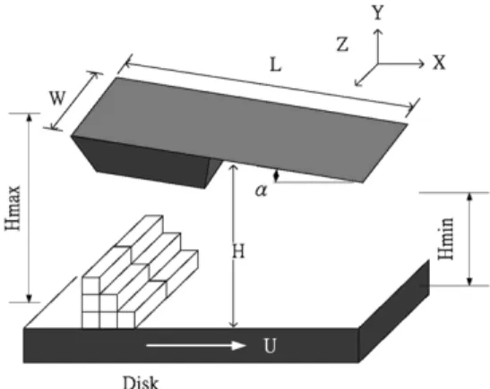
Fig. 1. Air bearing model in DSMC.
uses the DSMC method to develop the air bearing model. Pres-sure distributions between CD/DVD with smooth surfaces and the near-field optical disk are compared.
II. DSMC METHOD
The air bearing force and flying height analysis are crucial for slider air bearing design. In this paper, the flying pickup-head flies within the range of the mean-free path of gas molecules
( at STP for air).
At the head/disk interface, disk rotation brings air under the slider to create pressure and provides a lifting force that causes the head to fly above the disk. Unlike molecular dynamics methods, the DSMC method provides probability and average physical quantities instead of predicting the instantaneous state of each air molecular particle, since at standard atmo-spheric pressure, there are about 7400 air molecules in 65 cube nanometer volume. The average physical quantities assumption reduces significant calculation time. Hence, to construct models at nanoscale, the DSMC method is a good choice.
The gas under the slider is assumed to be dilute so that the in-teractions between particles are modeled as two-body collisions and the potential energy of particles is negligible compared to the kinetic energy. Since the real air is mixed by 4/5 nitrogen and 1/5 oxygen, it is complicated to deal with the polyatomic molecule and mixed gas using DSMC. This paper uses argon in computing averaged quantities, including momentum and ki-netic energy, instead of the real air molecules. The potential en-ergy and mean-free path of each air molecular is similar to those of argon. There are two kinds of boundary conditions amid the slider and the rotating disk: solid walls and fluxing reservoirs. The slider and disk are treated as solid wall and the four sides
1048 IEEE TRANSACTIONS ON MAGNETICS, VOL. 41, NO. 2, FEBRUARY 2005
at the region between the slider and disk are treated as fluxing reservoirs.
III. COMPUTATIONALRESULT
Fig. 1 shows a 3–D gas bearing configuration in the present DSMC method. The length L of the slider is prescribed as 4 and its width W is 3.3 . The pitch angle is 0.01 rad. The disk speed U is 10 m/s. The gas is chosen to be argon with
temperature and density . The
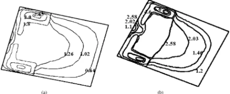
mean-free path of gas molecules of argon is 62.5 nm. Fig. 2 shows a slider with two rails that will be investigated in this paper. The minimum flying height appears at the rail 1.5 along the direction. The rail height is 0.7 . Fig. 3 shows a near-field optical disk with grooved surface. Unlike conven-tional optical disks, the recording layer of the near-field op-tical disk is on the disk surface. Hence, the recording tracks with the grooves and lands constitute disk roughness. The ge-ometry of a near-field optical disk is full of tracks on the disk surface although only two grooves are depicted in Fig. 3. A track pitch consists of a groove and a land. The groove depth is pre-scribed as 50 nm. The widths of the groove and land are 100 and 200 nm, respectively. When the distance between the slider and disk is around 50 nm, the disk groove effects cannot be ne-glected. It follows from calculation that the slider covers about eleven tracks when the slider is flying above the near-field op-tical disk. The grooves become reservoirs that store inside air molecules. Air molecules inside grooves when the slider covers eleven tracks maintain approximately the same density as those when the slider has not yet covered the tracks. Moreover, the number of air molecules inside grooves is always not ignorable. Fig. 4 compares pressure distributions on the bottom surface of a two-rail slider at flying height of 11 nm above a grooved disk and a disk with smooth surface. The lower pressure dis-tribution appears when the slider is flying above a grooved disk rather than a smooth disk. As a consequence, the lift force caused by a rotating grooved disk is lower than that causing by a rotating smooth disk. In a manner similar to Fig. 4, Figs. 5–7 compare slider pressures at different flying heights. The lower pressure in grooved disks represents that the air bearing will provide lower lift force. Hence, it is lighter slider mass that is suitable for grooved disks. The air bearing cannot carry the same weight of the slider when it flies above grooved disks.
Comparing Figs. 4(a), 5(a), 6(a), and 7(a) show that for grooved disks, slider pressure increases with lower flying height. Since lower flying height implies closer distance be-tween the slider and disk surface, such that air molecules collide with the slider bottom more frequently.
According to Figs. 4–7, the existence of disk grooves does not change the pattern of pressure distribution. The highest pressure among pressure distribution decreases with increasing flying height. Each of Figs. 4–7 shows that lower pressure appears when a slider flies above a grooved disk rather than above a smooth surface disk.
Grooves in tracks on near-field optical disk surface store al-most the same density of air molecules as that when the slider does not cover grooves. When the pressure between the slider and the land region changes since the slider flies above certain
Fig. 2. Geometry of slider with two rails.
Fig. 3. Near-field optical disk with grooved surface.
Fig. 4. Pressure distribution on slider at 11-nm flying height above (a) grooved disk and (b) smooth surface disk.
Fig. 5. Pressure distribution on slider at 16-nm flying height above (a) grooved disk and (b) smooth surface disk.
tracks, the groove region in those tracks can tune the pressure, in a manner similar to the effect of electrical capacitors that tuning the number of charges. However, when the slider flies higher, this tuning effect fades. Since the number of air molecules in
WANG et al.: STUDY OF AIR BEARING WITH GROOVED DISK SURFACE IN NEAR-FIELD OPTICAL DISK DRIVES 1049
Fig. 6. Pressure distribution on slider at 21-nm flying height above (a) grooved disk and (b) smooth surface disk.
Fig. 7. Pressure distribution on slider at 26-nm flying height above (a) grooved disk and (b) smooth surface disk.
the groove region remains stable, higher flying, i.e., longer dis-tance between slider and disk enlarges the control volume and the tuning effect due to grooves becomes no longer significant. Comparing Fig. 7(a) at 50-nm groove depth and Fig. 8 at 40-and 60-nm groove depths shows that rail regions maintain the same pressure distribution. Comparing Fig. 7(a) at 300-nm track pitch and Fig. 9 at 270- and 330-nm track pitches shows that pressure in rail regions remain the same.
IV. CONCLUSION
This paper showed that grooves in the near-field optical disk indeed affect pressure distribution and hence the lifting force on the slider. Computational results showed that grooved disks generate smaller pressure than smooth disks since grooves can accommodate air molecules and tune pressure. Further, track
Fig. 8. Pressure distribution on slider at 26-nm flying height for groove depth (a) 40 and (b) 60 nm.
Fig. 9. Pressure distribution on slider at 26-nm flying height for groove pitch (a) 270 and (b) 330 nm.
pitches and groove depths essentially do not affect pressure at rails.
REFERENCES
[1] G. A. Bird, Molecular Gas Dynamics and the Direct Simulation of Gas
Flows. Oxford, U.K.: Clarendon, 1994.
[2] F. J. Alexander, A. L. Garica, and B. J. Alder, “Direct simulation Monte Carlo for thin-film bearings,” Phys. Fluids, vol. 6, no. 12, pp. 3854–3860, 1994.
[3] W. Huang and D. B. Bogy, “Three-dimensional direct simulation Monte Carlo method for slider air bearings,” Phys. Fluids, vol. 9, no. 6, pp. 1764–1769, 1997.
[4] , “An investigation of slider air bearing with asperity contact by a three-dimensional direct simulation Monte Carlo method,” IEEE Trans.
Magn., vol. 34, no. 1, pp. 1810–1812, Jan. 1998.
[5] N. Liu and E. Y. K. Ng, “The posture effects of a slider air bearing on its performance its a direct simulation Monte Carlo method,” J. Micromech.
and Microeng., vol. 11, pp. 463–473, 2001.
[6] D. M. Phillips and M. S. Jhon, “Dynamic simulation of nanoscale lubri-cation films,” J. Appl. Phys., vol. 91, no. 10, pp. 7577–7579.