A wavelength and polarization selector made of holographic polarization beamsplitting
cubes for optical communications
Jen-Tsorng Chang, Der-Chin Su, and Yang-Tung Huang
Citation: Applied Physics Letters 70, 1805 (1997); doi: 10.1063/1.118697 View online: http://dx.doi.org/10.1063/1.118697
View Table of Contents: http://scitation.aip.org/content/aip/journal/apl/70/14?ver=pdfcov
Published by the AIP Publishing
Articles you may be interested in
Combined holographic-mechanical optical tweezers: Construction, optimization, and calibration
Rev. Sci. Instrum. 80, 083703 (2009); 10.1063/1.3196181
Silicon light emitting diodes emitting over the 1.2 – 1.4 m wavelength region in the extended optical communication band
Appl. Phys. Lett. 92, 161108 (2008); 10.1063/1.2916824
Experimental demonstration of a wavelength demultiplexer based on negative-refractive photonic-crystal components
Appl. Phys. Lett. 91, 091117 (2007); 10.1063/1.2779927
Room temperature demonstration of Ga N Al N quantum dot intraband infrared photodetector at fiber-optics communication wavelength
Appl. Phys. Lett. 88, 143101 (2006); 10.1063/1.2186108
Photorefractive polymer composite operating at the optical communication wavelength of 1550 nm
Appl. Phys. Lett. 85, 4561 (2004); 10.1063/1.1826224
This article is copyrighted as indicated in the article. Reuse of AIP content is subject to the terms at: http://scitation.aip.org/termsconditions. Downloaded to IP: 140.113.38.11 On: Fri, 03 Oct 2014 05:54:58
A wavelength and polarization selector made of holographic polarization
beamsplitting cubes for optical communications
Jen-Tsorng Chang and Der-Chin Sua)
Institute of Electro-Optical Engineering, National Chiao-Tung University, HsinChu 30050, Taiwan, Republic of China
Yang-Tung Huang
Department of Electronics Engineering and Institute of Electronics, National Chiao-Tung University, HsinChu 30050, Taiwan, Republic of China
~Received 26 November 1996; accepted for publication 3 February 1997!
We present a combined wavelength-polarization selector made of holographic polarization beamsplitting cubes in series. Each unit cube comprises a pair of prisms and a transmission-type phase volume hologram. The assembled selector, when examined with an intensity modulated beam of known polarization state, demonstrated our designated target. © 1997 American Institute of
Physics. @S0003-6951~97!03014-3#
A polarization-selective element is essential in optical information processing, magneto-optical pickup, and optical switching.1–6 A conventional polarization-selective element is made of birefringence crystals or a pair of right-angle prisms sandwiched with a special multilayer dielectric film. Several holographic polarization-selective elements were proposed in recent years.3–7 Kostuk et al. proposed a substrate-mode guiding holographic polarization-selective element using a transmission-type phase volume hologram with large diffraction angle.6 The element requires an addi-tional input coupling hologram which, in turn, needs the same diffraction efficiencies for different polarization states, making the element difficult to fabricate. The Kato et al.3 and Huang7 groups presented holographic polarization-selective element with a smaller diffraction angle which can be used in multichannel optical switching systems. We have also introduced yet another type of polarization-selective el-ement made of substrate-mode stacked polarization-selective holograms that can be used as a four channel polarization and wavelength separation element.8In this letter, we further propose a design of using holographic polarization beam-splitting cubes in series for wavelength and polarization se-lection in optical communications.
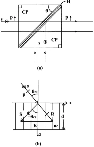
The structure of a unit holographic polarization beam-splitting cube is shown in Fig. 1~a!. It consists of a pair of right-angle prisms and a transmission-type phase volume ho-logram ~H!. The normal incident beam travels in the first prism without changing direction and strikes the sandwiched hologram at 45°. According to Kogelnik’s coupled-wave theory,9 the diffraction efficiencies of a transmission-type phase volume hologram for the s- and the p-polarization states near Bragg condition are
h5sin 2~
A
n21j2! ~11j2/n2! , ~1! where n5ng5 pn1dl
A
ucosur1cosur2ufor s polarization, ~2a!
n5np5ng cos~ur12ur2! for p polarization ~2b!
and
j5 2DlK
2d
8pn cosur2
, ~3!
respectively, where n is the coupling coefficient, j is the detuning factor,l is the reconstruction wavelength, Dl is the wavelength shift with respect to the central wavelengthl, K is the grating vector, d is the grating thickness, n1 is the
amplitude of the index modulation, and ur1 andur2 are,
re-spectively, the reconstruction and the diffraction angles in the phase volume hologram. From Eq. ~2!, it is seen that there is no diffracted light of p-polarization state since (ur1
2ur2)56p/2. Based on the last 6p/2 condition, if the
grating vector K@Fig. 1~b!# recorded on the hologram is such that its Bragg angle is ur1545°, then the direction of the
diffracted beam S will be perpendicular to that of the recon-struction beam R in the emulsion as is shown in Fig. 1~b!. Consequently, the s-polarization state is 90° diffracted since the p-polarization state passes through the hologram without changing direction.
In this letter, two types of holograms were purposely developed for the readily available 632.8 nm He–Ne laser line and 780 nm GaAs/GaAlAs diode laser line. These are called H1 and H2, respectively. The holograms were re-corded on laboratory-made dichromated gelatin~DCG! using He–Cd laser 441.6 nm line and the technique of the longer wavelength reconstruction with the shorter wavelength re-cording. The final thickness of the fixed emulsion layer is 12
mm~a-step measurement!, and its averaged refractive index (n) is 1.52. Their index modulation strengths for high polar-ization extinction ratio are chosen to be 0.0186 and 0.0229, respectively. These holograms were cemented between the hypotenuse faces of two right-angle BK7 prisms (n 51.517) with Norland 65 UV curing optical cement (n 51.52). The wavelength and polarization selective charac-teristics of H1 and H2 cubes were investigated with pre-pared polarization states of the two wavelengths ~632.8 and 780 nm!. The diffraction efficiency is affected by the Bragg detuning factor. And the results of the diffraction efficiency versus wavelength of these two holograms are shown in Fig.
a!Electronic mail: [email protected]
1805 Appl. Phys. Lett. 70 (14), 7 April 1997 0003-6951/97/70(14)/1805/3/$10.00 © 1997 American Institute of Physics
This article is copyrighted as indicated in the article. Reuse of AIP content is subject to the terms at: http://scitation.aip.org/termsconditions. Downloaded to IP: 140.113.38.11 On: Fri, 03 Oct 2014 05:54:58
2. The circles and dots represent the experimental data of the
s and the p polarizations, respectively. The full width at half
maximum~FWHM! of 632.8 and 780 nm peaks are, respec-tively, ;30 and ;40 nm. The continuous lines marked H1 and H2 are the theoretical diffraction efficiency curves for the s and the p polarization from Eqs. ~1! and ~2!. The the-oretical diffraction efficiency curves for the p polarization
are nearly zero and hence are close to the ordinate and hardly seen in Fig. 2. These curves are qualitatively comparable to the experimental data. Therefore, these H1and H2 holo-graphic cubes can serve as a wavelength dependent polarization-selective element. Holographic polarization beamsplitting cubes for other wavelengths ~such as those used in fiber communications! can be possibly made with the same techniques.
In order to demonstrate the overall performance of these holographic cubes as a wavelength and polarization selector, we assembled two H1 and two H2 holographic cubes in series. The structure is shown in Fig. 3. The hologram planes
FIG. 1. ~a! The structure of a holographic polarization beamsplitting cube. CP stands for the coupling prism, s and p the s and the p-polarization states, and H the hologram. ~b! Reconstruction geometry in the emulsion of a volume phase hologram. R and S represent the reconstruction and the dif-fraction beams,ur1,andur2the reconstruction and diffraction angles, and K
the grating vector.
FIG. 2. Experimental diffraction efficiencies of H1 and H2 vs wavelength.
S polarizations are shown in open circle and p polarizations in dots. The
smooth curves show the theoretical predictions of Eqs.~1! and ~2!.
FIG. 3. The experimental setup for wavelength and polarization selectivities of the assembly using holographic polarization cubes in series. C stands for the chopper, FLC the ferroelectric liquid crystal, and H1 and H2 the holo-grams.
FIG. 4. ~a! Oscilloscope readout for each channel of the assembly using 632.8 nm input beam.~b! The channel readout for the 780 nm input beam.
1806 Appl. Phys. Lett., Vol. 70, No. 14, 7 April 1997 Chang, Su, and Huang
This article is copyrighted as indicated in the article. Reuse of AIP content is subject to the terms at: http://scitation.aip.org/termsconditions. Downloaded to IP: 140.113.38.11 On: Fri, 03 Oct 2014 05:54:58
of incidence of the first two H1 cubes were arranged to be perpendicular to each other. The hologram planes of the fol-lowing two H2 cubes were also perpendicular to each other. It demonstrated that different wavelength input beams were diffracted selectively with the specific polarization states by the individual channel in the assembly. In Fig. 3, the input laser signals were incident from the left to the assembly. A chopper ~C! and a ferroelectric liquid crystal ~FLC! were inserted between the laser and the assembly for the carrier signal intensity and polarization modulation. The outputs from each channel of the assembly were monitored by an oscilloscope. Figure 4~a! shows those for the 632.8 nm input beam. The carrier signals produced by the chopper action enveloped by the FLC in alternating phases only appeared in channels 1 and 2, consistent with the character of H1 cubes. There were no signal outputs in channels 3 and 4 as was expected. Figure 4~b! shows the signal outputs of the 780 nm input beam in channels 3 and 4, reflecting the proper func-tioning of H2 cubes. There were no signal outputs in chan-nels 1 and 2.
In summary, it is clear that the assembly of our holo-graphic polarization beamsplitting cubes in series is a prac-tical wavelength-polarization selector that can be useful in optical communication.
The authors would like to thank Professor W.-H. Chen for the useful discussions and critical reading of this letter. This work was supported by the National Science Council of the Republic of China under Contract No. NSC83-0417-E-009-022.
1J. B. McManus, R. S. Putnam, and H. J. Caulfield, Appl. Opt. 27, 4244 ~1988!.
2
G. T. Sincerbox, Proc. Soc. Photo-Opt. Instrum. Eng. 935, 63~1988!. 3M. Kato, H. Ito, T. Yamamoto, F. Yamagishi, and T. Nakagami, Opt. Lett.
17, 769~1992!.
4Q. W. Song, M. C. Lee, P. J. Talbot, and E. Tam, Opt. Lett. 16, 1228 ~1991!.
5
Q. W. Song, M. C. Lee, and P. J. Talbot, Appl. Opt. 31, 6240~1992!. 6R. K. Kostuk, M. Kato, and Y.-T. Huang, Appl. Opt. 29, 3848~1990!. 7Y.-T. Huang, Appl. Opt. 33, 2115~1994!.
8J.-T. Chang, D.-C. Su, and Y.-T. Huang, Appl. Phys. Lett. 68, 3537 ~1996!.
9
H. Kogelnik, Bell Syst. Tech. J. 48, 2909~1969!.
1807
Appl. Phys. Lett., Vol. 70, No. 14, 7 April 1997 Chang, Su, and Huang
This article is copyrighted as indicated in the article. Reuse of AIP content is subject to the terms at: http://scitation.aip.org/termsconditions. Downloaded to IP: 140.113.38.11 On: Fri, 03 Oct 2014 05:54:58