三維中國水墨畫之快速合成演算法
47
0
0
全文
(2) 三維中國水墨畫之快速合成演算法. 研究生: 林俊男. 指導教授: 施仁忠 教授. 國立交通大學資訊科學系. 摘. 要. 水墨畫在中國傳統文化藝術中是具有相當悠久歷史的一項藝術,使用墨與水 調和出各種不同濃淡的墨色,用墨色表現出的明暗對比來描繪出一幅景物。在現 今已經發展出來的許多模擬中國水墨畫的技術中,我們可以看到許多不錯的結 果。但是因為演算法以及硬體的限制,執行速度不夠快,所以在某些應用程式上 鮮少被使用到。本篇論文研究的重點,便是改善水墨畫效果產生的運算速度。在 本篇論文中,我們使用硬體語言來撰寫,利用 GPU 來運算,將不同的影像技術加 入模擬程式中,最後將系統產生的結果利用渲染的技術,建立一個自動產生水墨 畫效果的即時互動式系統。. I.
(3) A Fast Algorithm for the Synthesis of 3D Chinese Ink Paintings. Student: Chun-Nan Lin. Advisor: Dr. Zen-Chung Shih. Institute of Computer and Information Science National Chiao-Tung University. ABSTRACT. The ink painting is an art with long history in Chinese culture. By mixing water and ink properly, we can obtain different concentrations to show the contrast of an object. Several techniques focused on simulating Chinese ink paintings can yield good results. But they can not have good efficiency when used in some applications because of the limitation in hardware and algorithm. In this thesis, the major contribution is to improve the performance of synthesizing the Chinese ink styles. We use each random particle which is generated in 3D scene to draw billboard and use High-Level Shader Language (HLSL) to write our program code which is running in the GPU. We build a system which puts different image space techniques in shader program and mix them to generate a scene in Chinese ink painting style automatically.. II.
(4) Acknowledgements. First of all, I would like to show my gratitude to my advisor, Prof. Zen-Chung Shih for his patience and guidance. Also, I am grateful to all the members in Computer Graphics and Virtual Reality Laboratory for their useful suggestion and encouragement in these days.. I want to dedicate the achievement of this work to my family. Without their support, I couldn’t fully focus on my study.. III.
(5) Contents. ABSTRACT (IN CHINESE)…………………………………………………………I ABSTRACT (IN ENGLISH)…………………………………………………………II ACKNOWLEDGEMENTS……………………………………………...…………III CONTENTS…………………………………………………………………………IV LIST OF TABLES…………………………………………………………………..VI LIST OF FIGURES………………………………………………………………..VII CHAPTER 1. INTRODUCTION………………………………………………...1. 1.1 MOTIVATION……………………………………………………………….1 1.2 OVERVIEW………………………………………………………………….2 CHAPTER 2. RELATED WORKS………………………………………………6. 2.1 PAINTERLY RENDERING USING PARTICLES………………………….6 2.2 INK DIFFUSION…………………………………………………………….8 2.3 SHADER PROGRAMMING……………………………………………...9 CHAPTER 3. THE RENDERING……………………………………………10. 3.1 PREPROCESSING…………………………………………………………11 3.2 EXTRACTING 3D INFORMATION……………………………………...13 3.3 PARTICLES CULLING AND PARTICLE DENSITY…………………….14 3.4 DRAW BILLBOARDS...…………………………………………………...16 3.4.1 Billboard Size……………………….……………………………..17 IV.
(6) 3.4.2 Billboard Orientation………………………………………………..18 3.4.3 Brush Stroke………………………….……………………………...19 3.4.4 Multiple Passes for Particle Rendering……………………………..20 3.5 SILHOUETTE GENERATION……………………………………………21 3.6 INK DIFFUSION………………………………………………………...…22 CHAPTER 4. IMPLENENTATION RESULTS………………………………24. CHAPTER 5. CONCLUSIONS AND FUTURE WORKS…………………….34. REFERENCE……………………………………………………………………….36. V.
(7) List of Tables. Table 4.1: Performance measurements……………………………………………...33. VI.
(8) List of Figures. Figure 1.1: System flow chart…………………..……………………….……...…….3 Figure 3.1: Particles distribution with different density. ...………………………...12. Figure 3.2: The fifteen thresholds for quantization. ……………………….………14 Figure 3.3: The equation of actual number of particles …………………………….16 Figure 3.4: Particle size with different mPartSize……………………….…………..18 Figure 3.5: Rotating billboard.…………………..………………………….……….19 Figure 3.6: Different Brush texture.……………………..…………………...……...20 Figure 3.7: Order of eight neighbor directions…………………………….………21 Figure 3.8 The capillary phenomenon..…………………………………………….22 Figure 3.9 The real ink diffusion effect..…………………………………….………22 Figure 4.1: Intermediate results of the rendering...…………………………...……..26 Figure 4.2: Sparrow with silhouette edges.…………………………………...…...27 Figure 4.3: Different View of Sparrow……………………………………….……...28 Figure 4.4: Aqua1 without silhouette edges.………………...…………….………...29. VII.
(9) Figure 4.5: Aqua2 without silhouette edges.………....…………………….………..30 Figure 4.6: Different view of Aqua2………………………………………..……..31 Figure 4.7: Willow with silhouette edges………………………………...………..32. VIII.
(10) Chapter 1 Introduction. 1.1 Motivation In some computer-related applications such as computer games or virtual environment, they are rarely rendered in Chinese visual styles because the rendering of the Chinese ink painting is hard to reach real-time performance. In the past, several studies that focused on Chinese ink painting yield good results. Although these results have good quality and giving us a deep impression, their performance is not good enough. In general, if we want to enhance the performance, we need to lose some quality of the results or upgrade our computer hardware. In order to improve the rendering performance, we propose a method that automatically synthesizes the Chinese ink painting style from a 3D model by using GPU. Users can freely navigate around the scene in the Chinese painting styles interactively.. 1.
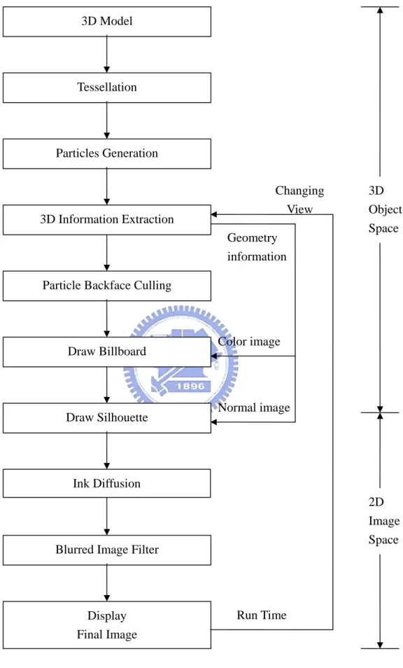
(11) 1.2 Overview Chinese ink paintings typically consist of simple strokes that convey the “deep feeling” of artist but not just color filling or pattern placing. Synthesizing the style of the Chinese ink painting is not at all trivial. Such paintings typically use brushes and ink, and value the expression of the artistic conception far beyond precisely conveying the appearance of the painted subjects. A painter communicates her frame of mind to the viewers by blending the effects of brushes and ink.. The main goal of this thesis is to render the 3D object with Chinese ink painting style. In the past, several methods which simulate Chinese ink paintings are almost implemented in software that is relying on the computing power of CPU. For this purpose, we use the hardware accelerated method, that is writing shader programs which execute on the GPU (Graphics Processing Unit) by means of HLSL instead of assembly or any high-level language. Shader replaces a portion of the fixed function pipeline. We can obtain a huge amount of flexibility in graphical effects that we can achieve. First we use the geometric information of 3D model to generate particles. Then, draw billboards and silhouette. Apply ink Diffusion to result and use image filter for post process. The flow chart of our proposed system is shown in Figure 1.1. The function of each part is described as follows:. 2.
(12) 3D Model. Tessellation. Particles Generation Changing View. 3D Information Extraction. Geometry information. 3D Object Space. Particle Backface Culling. Color image. Draw Billboard. Normal image. Draw Silhouette. Ink Diffusion 2D Image Space. Blurred Image Filter. Run Time. Display Final Image. Figure 1.1: System flow chart. 3.
(13) (1) Tessellation:Geometric primitives, including points, lines, triangles, and polygons, are referenced in the vertex data with index buffers.. (2) Particles Generation:Generate random particles from each face in the 3D model. Each particle also has a random color value.. (3) 3D Information Extraction:We use DirectX to render 3D model with vertices, edges, faces and light sources. Output color image, normal image, position image in one pass or three pass (depend on hardware).. (4) Particle Backface Culling:Clipping, back face culling, attribute evaluation, and rasterization are applied to the transformed particles.. (5) Draw Billboard:Each billboard is a brush texture. We draw a billboard for each particle by using the color image for reference texture map. Depth buffer is applied to each particle.. (6) Draw Silhouette:Find the silhouette edges using normal map of the reference texture image.. (7) Ink Diffusion:Simulate the motion of ink on the rice paper.. (8) Image Filter:Use blurred image filter or blend with the color image to produce final image.. 4.
(14) 1.3 Thesis Organization. This thesis is organized as follows. In chapter 2, we review the related works in non-photorealistic rendering. We describe techniques and algorithms for ink painting in chapter 3. We show implementation in chapter 4, including the performance data. Then we make discussion on these results. Finally, chapter 5 concludes this work and addresses some future works.. 5.
(15) Chapter 2 Related Works. 2.1 Painterly Rendering using particles Haeberli [6] described a system for creating painterly images by using brush strokes which obtain their attributes (position, color, size, etc.) from reference pictures containing photographic or rendered images. The use of reference pictures simplifies the creation of artistic images and allows fast and direct control of the process.. The brush strokes of Haeberli’s system are placed in screen space, which is sufficient for still images but leads to a “shower door” effect in animated sequences. In Meier’s system [13], this problem is addressed by using particles to control the placement of brush strokes. The particles are rendered using 2D textures which are first sorted by the distance to the user and then blended with each other.. In photorealistic rendering, particle systems can be used to synthesize complex. 6.
(16) natural phenomenons like water or fire using simple geometric structures. Reeves and Blau [15] proposed a technique using particle systems to create complex objects like trees. Kaplan et al. [9] utilizes particle systems in a way similar to Meier, but uses so-called geograftals instead of bitmaps to create brush strokes.. Meier’s system was already converted into a real-time system by Drone et al. [2]. This system is designed to run even on previous hardwares without vertex and pixel shaders. In addition, the strokes are depth sorted in each frame. Although this results in an excellent image quality, it has additional impact on the rendering speed.. Michael and Daniel [7] extend Meier’s system and introduce several optimizations to achieve a performance suitable for real-time applications. The amount of particles is dynamically changed to achieve an optimal trade-off between screen coverage and rendering speed. In addition, a manual depth test carried out by the graphics hardware allows the brush strokes to be blended on the screen without depth sorting the particles. The transfer of a great deal of calculations from the CPU to the GPU results in a higher speed than is accomplished in Drone’s system, while the user-defined creation of reference pictures allows more flexibility. By making some modifications and extensions to Michael and Daniel‘s system, we can improve the rendering speed of Chinese ink painting. Detailed rendering algorithm will be. 7.
(17) discussed in chapter 3.. 2.2 Ink Diffusion The special effect of ink diffusion is produced by the incredible absorbency of Hsuan paper. Ink diffusion is widely used in Chinese ink painting and it is also what differentiates Chinese ink painting from Western painting. A technique proposed by Lee [10] efficiently rendered oriental black ink paintings with realistic diffusion effects. The system proposed by Lee can simulate ink diffusion based on a variety of paper types and ink properties. However, there has been no mechanism presented about the simulation of blending effects of two or more strokes. Small [16] proposed a parallel approach to predict the motion of pigment and water on the paper, which computes the status in each paper cell repeatedly to achieve realistic diffusion effects. A more sophisticated paper model was proposed by Curtis and Anderson [1]. With a more complex shallow water simulation, they can simulate realistic diffusion effects of watercolor. Sheng-Wen Huang et al. [8] proposed a physically-based ink diffusion model by simulating the interaction among water particles, carbon particles and paper. This model is the major reference for the ink diffusion simulation in this thesis. By implementing Huang’s model, we can achieve the requirement for an interactive system. 8.
(18) 2.3 Shader Programming The constant progress of shader language makes us more convenient to use powerful GPU capability. So we may transfer a great deal of calculations from the CPU to the GPU. By using High-level shader language, which is a C++ like language, instead of assembly language makes less confusion to write a shader program. In “Shader X2 “[3], many tips and tricks help us to understand how to design and write an effect file whatever you want, such as lighting, shadow, geometry transformation, and image space filter. In “GPU Gems” [4], it also contains shader program which involves basic and advanced rendering techniques or combination of two or more. Our system renders a 3D scene efficiently by using the rendering technique which is almost written by shader program.. 9.
(19) Chapter 3 The Rendering The rendering process of our proposed algorithm consists of seven steps. Except steps 1, 3 and 6, we use shader language to implement the algorithm as follows:. 1.. A preprocess to generate 3D particles on polygonal meshes.. 2.. Extract 3D information of the 3D scene, which will be used in next two steps.. 3.. Find particles in back face and adjust particle density.. 4.. Draw billboard for each particle in screen space.. 5.. Generate silhouettes from reference normal map in image space.. 6.. Apply ink diffusion effect.. 7.. Use image filter to modify the intermediate result.. 10.
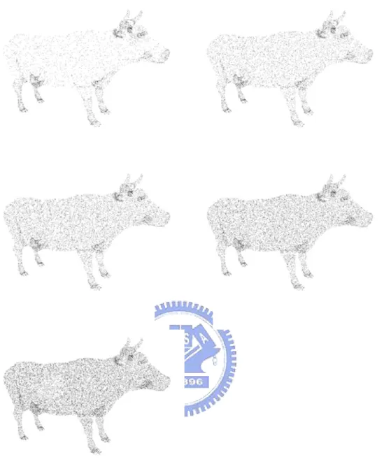
(20) 3.1 Preprocessing In the preprocessing step, we generate particles for the polygonal objects in 3D scene. These particles will be used later to place the brush strokes. All particles are located inside the triangles of the polygonal mesh. Depending on the area of a triangle and a user-defined density, a certain number of particles are generated in each triangle. The number of particles in each triangle is determined by the area of triangle and particle density as follows:. N =. Area. x. Density. We can significantly accelerate the preprocessing step by carefully determining the density of the brush strokes. If the density is too high, a tremendous amount of particles is created, which has negative effects on performance and memory usage.. 11.
(21) Figure 3.1: Particles distribution with different density. Furthermore, we also calculate the ratio for each triangle by using triangle’s area. ratio =. current _ triangle _ area , Max_triangle_area is the triangle with the largest Max _ triangle _ area. area in the polygonal objects of the 3D scene. With this parameter, we could adjust particle size by their triangle area in the fourth step. To get a more natural result, we. 12.
(22) also use random number from 0.0 to 1.0 to generate color variation for each particle and store it. This will be used in determining the color of brush stroke.. 3.2 Extracting 3D Information DirectX has its own mesh file format for 3D object — *.x. We convert the 3D model file format to DirectX file format. Then we render the 3D model with Gouraud shading by using shader program. By using the function of multiple rendertarget in DirectX, we could output the information image to texture. With this method, we can get two textures include color image and normal image. Color image will be used in sec 3.4 as reference texture map and normal image will be used in sec 3.5 to generate silhouette edges.. Before output the color image, we quantize all pixels in the interior area into fifteenth color levels. Color ranging from pure black to pure white is distributed from 0.0 to 1.0. From the color distribution histogram as shown in the top of Figure 3.2, we set fourteen thresholds for color quantization: 0.25, 0.3, 0.35, 0.4, 0.433, 0.466, 0.5, 0.525, 0.55, 0.575, 0.6, 0.633, 0.666, 0.7. A pixel located at any place in color distribution histogram will be quantized to a relative threshold color value. The color mapping table is also shown in the bottom of Figure 3.2. 13.
(23) Color Range. 0.0~0.25. 0.25~0.3. 0.3~0.35. 0.35~0.4. Quantization. 0.25. 0.3. 0.35. 0.4. 0.4~0.433. 0.433~0.466. 0.466~0.5. 0.5~0.525. 0.525~0.55. 0.55~0.575. 0.575~0.6. 0.433. 0.466. 0.5. 0.525. 0.55. 0.575. 0.6. 0.6~0.633. 0.633~0.666. 0.666~0.7. 0.7~1.0. 0.633. 0.666. 0.7. 0.8. Figure 3.2: The fifteen thresholds for quantization. 3.3 Particles Culling and Particle Density Before the billboards are rendered, typical optimization steps, such as backface culling and clipping should be performed. This can save a lot of processing time. Although the remainder of these particles after culling is visible, we don’t need to. 14.
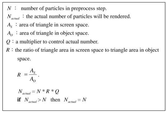
(24) draw all of them. The actual number depends on the distance of the camera to each surface and the size of the brush strokes.. 3.3.1 Particles Culling. For performance enhancement, we only calculate one particle in each triangle instead of all the particles. If this particle is visible, then the whole particles in this triangle are visible. To determine a particle is visible or not, we calculate the dot product of the normal vector and vector from eye to particle in world space.. 3.3.2 Desired Particle Density. After the backface culling, we also need to control the number of particles that will be rendered in screen space. Because the actual area of each triangle in screen space is not the same as in object space, we calculate the ratio of triangle area in screen space to triangle area in object space for each triangle. Then the actual number of particles of each triangle which will be rendered at run-time can be obtained according to the following equation:. 15.
(25) N : number of particles in preprocess step. N actual :the actual number of particles will be rendered.. AS :area of triangle in screen space. AO :area of triangle in object space. Q:a multiplier to control actual number. R:the ratio of triangle area in screen space to triangle area in object space. R =. AS . AO. N actual = N * R * Q if N actual > N then N actual = N Figure 3.3: The equation of actual number of particles. 3.4 Draw Billboards This step is the most expensive one. Each particle is rendered by billboard. Thousands of brush strokes have to be rendered simultaneously, which can be accomplished by programming the graphics card directly (using the vertex and pixel shaders), and by several other optimizations. The resulting image is composed of a large amount of billboards which represent different strokes. In the previous step, the optimizations are executed and the remainders of the particles are all visible.. 16.
(26) 3.4.1 Billboard Size. Before rendering the billboard for each particle, we need calculating the billboard size on screen space. To determine the final size of billboard, we have two parameters — ratio and distance. In the section 3.1, we calculate the ratio of the triangle’s area to the largest triangle’s area in the polygonal objects of the 3D scene for each triangle surface in 3D model in world space. Then we use the distance from the particle to the viewer as our second parameter. So the billboard size for each particle is calculated below:. S = dist _ to _ viewer ∗ ratio ∗ mPartSize ,. where mPartSize is user-defined parameter to adjust final size of particle. The billboard is a rectangle whose width to height is 1:4.. 17.
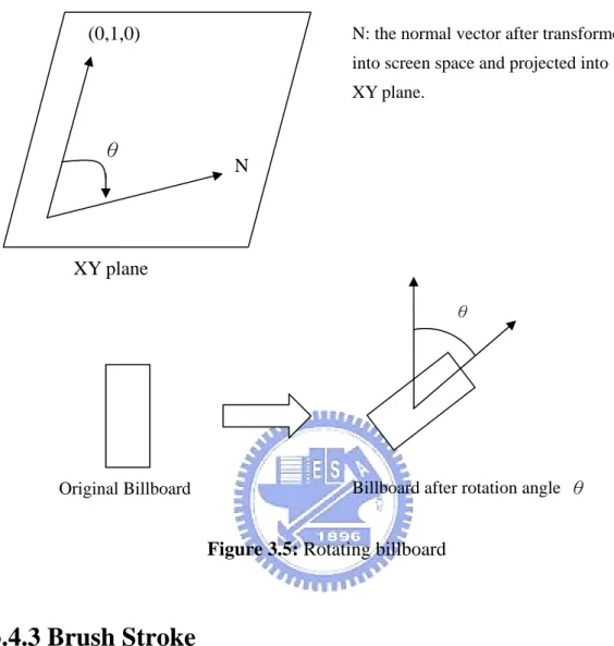
(27) (a) mPartSize = 1.0. (b)mPartSize = 1.5. (c) mPartSize = 2.0 Figure 3.4: Particle size with different mPartSize. 3.4.2 Billboard Orientation To make our results more variation, we rotate the billboard with the angle θ depend on its normal vector. First we transform the normal vector into screen space and project it into XY plane. Then calculate the angle θ between it and the Y-axis in screen space. Finally we can rotate the billboard with the angle θ clockwise. As shown in Figure 3.5.. 18.
(28) (0,1,0). N: the normal vector after transformed into screen space and projected into XY plane.. θ. N. XY plane θ. Billboard after rotation angle θ. Original Billboard. Figure 3.5: Rotating billboard. 3.4.3 Brush Stroke. The color of each brush stroke is computed by accessing the color reference texture which is generated from extraction of 3D information. So we need texture coordinate to lookup this texture. For this purpose, the screen space position of the particle is needed that describes the coordinates which are used to access the reference pictures. The screen coordinates are calculated in the vertex program and subsequently scaled and biased to be in the range (0.0~1.0) that is needed for texture. 19.
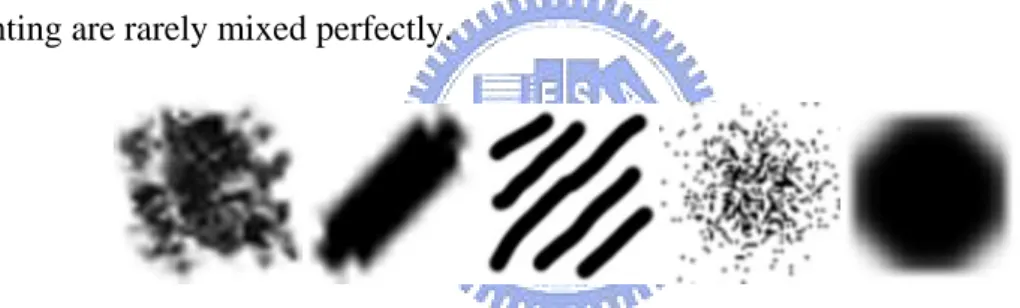
(29) access. The coordinate u and v are calculated as below. u = ( x / w ) ∗ 0 .5 + 0 .5. ,. v = (− y / w) ∗ 0.5 + 0.5. The color of the reference image at that position is then used as color for the billboard (and consequently for the brush stroke, after multiplying with the brush texture). By the way, we have five brush texture patterns which can be used in the billboard as shown in Figure 3.6. In the preprocessing step, we stored a slight color variation for each particle. It will be added here. This results in images that are natural, since the colors of a real painting are rarely mixed perfectly.. Figure 3.6: Different Brush texture. 3.4.4 Multiple Passes for Particle Rendering. Now we can render all visible particles (billboards) with the reference image and brush texture. Michael and Daniel‘s system [7] render all particle in one pass. To get a more layered and smooth result, we use a rendering technique with nine passes for drawing billboard. This means each particle will be rendered nine times. Except the 20.
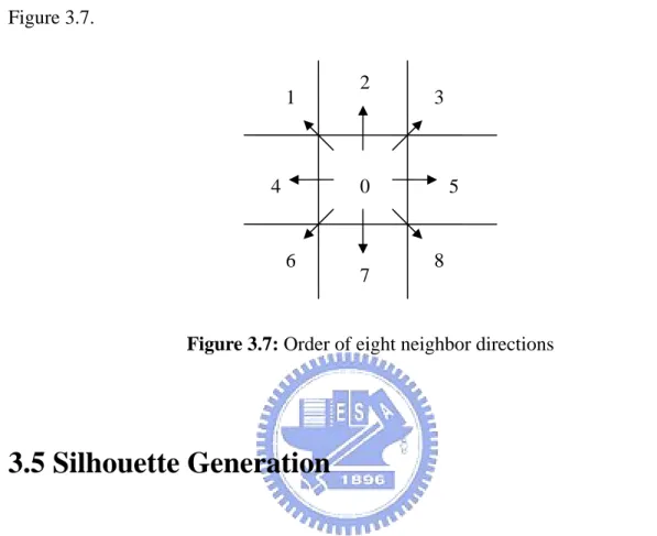
(30) first pass, the next eight passes we will give all particles offset and direction. Thus each particle will move to one of the eight neighbor direction in order, as shown in Figure 3.7. 2. 1. 4. 3. 0. 6. 7. 5. 8. Figure 3.7: Order of eight neighbor directions. 3.5 Silhouette Generation To enhance our result before diffusion, we add silhouette on our image after rendering billboard. In order to generate the silhouette, we use the normal map to calculate it. For each pixel in normal map, we calculate the dot product with four neighbor pixel’s value and sum up. Then set a threshold, if the value is greater than it, this pixel is silhouette edge point. However, some model is not suitable for adding silhouette. So we will determine it depending on circumstances.. 21.
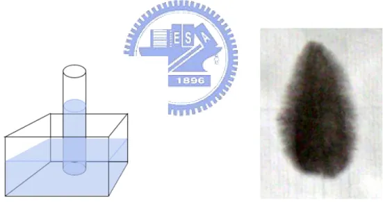
(31) 3.6 Ink Diffusion Ink diffusion is caused by the capillary action of water between fibers and the gradient of the quantity of water in paper cells. In Figure 3.5, a thin tube is placed in a container filled with water with one end in the water and the other end in the air. The liquid will rise inside the tube and the liquid surface inside the tube is higher than the surface of the outside water. This phenomenon can also be observed in the ink diffusion in paper. The typical paper is composed of fibers which are positioned in random position and random direction in which small holes and spaces between fibers act as thin capillary tubes for carrying water away from the initial area, and create diffusion, as shown in Figure 3.6.. Figure 3.8 The capillary phenomenon.. Figure 3.9 The real ink diffusion effect.. In this thesis, we implement Huang’s [8] physically-based model of ink diffusion for the process of ink diffusion. Then we apply this model for the intermediate result generated in the previous step.. After the process of ink diffusion by using physical-based model, we get a. 22.
(32) Chinese ink style image. However some small sharp part maybe happen, we apply a simple 3x3 blurred image filter. Some other image filter could be used here, such as blending, Gaussian blur.. 23.
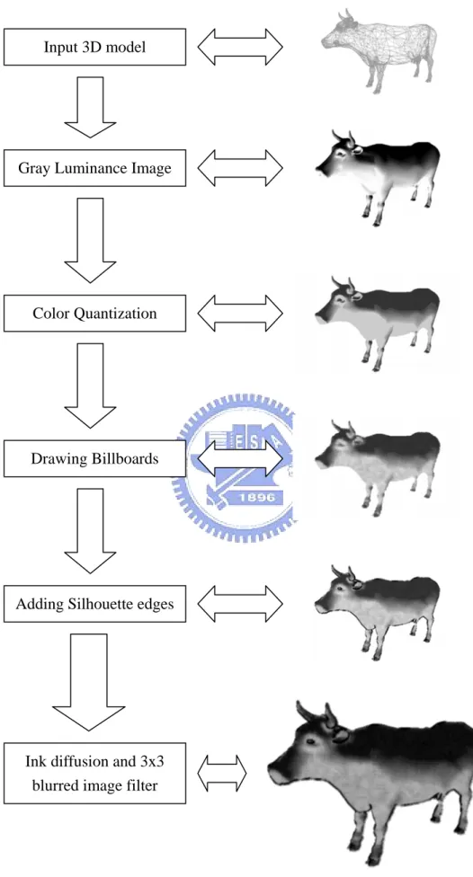
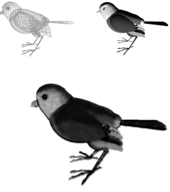
(33) Chapter 4 Implementation Results In this chapter, the implementation and results are presented. Our system is implemented in C++ language and The DirectX Software Development Kit on PC with P4 3.4GHz CPU, 2048 MB RAM and 6600GT. Figure 4.1 is the system flow chart. The input is a 3D object model and then luminance image is constructed. Quantize the luminance image and output as reference color image. Draw billboard depending on reference color image and adding silhouette edges. Finally ink diffusion and image filter are applied to synthesize the final results. Figure 4.2 to 4.5 are the synthesized results of Chinese ink painting. The upper image of each figure is the luminance image after shading and lower image is the synthesized results. Table 4.1 is the performance measurements of our system. The resolution of the image size is 640 x 480. The first column refers to the Figure. The second column is the numbers of faces of the 3D object model and the third column is the number of particles. The fourth column is the FPS(frame per second) without applying ink 24.
(34) diffusion. The fifth column displays the computation time of ink diffusion.. 25.
(35) Input 3D model. Gray Luminance Image. Color Quantization. Drawing Billboards. Adding Silhouette edges. Ink diffusion and 3x3 blurred image filter. Figure 4.1: Intermediate results of the rendering. 26.
(36) Figure 4.2: Sparrow with silhouette edges. 27.
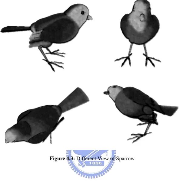
(37) Figure 4.3: Different View of Sparrow. 28.
(38) Figure 4.4: Aqua1 without silhouette edges. 29.
(39) Figure 4.5: Aqua2 without silhouette edges. 30.
(40) Figure 4.6: Different view of Aqua2. 31.
(41) Figure 4.7: Willow with silhouette edges. 32.
(42) # Faces. # Particles. FPS. Ink Diffusion Time. without Diffusion. (sec). Figure 4.1. 9353. 219010. 18. 0.4922. Figure 4.2. 6464. 30708. 36. 0.3575. Figure 4.4. 1890. 8423. 54. 0.3471. Figure 4.5. 2498. 108912. 33. 0.4390. Figure 4.7. 4046. 209207. 27. 0.3703. Table 4.1: Performance measurements. 33.
(43) Chapter 5 Conclusions and Future Works In this thesis, we propose a system for interactive synthesis of Chinese ink painting. A specific 3D object model is drawn automatically with billboards and silhouettes. Then we apply ink diffusion and image filter to intermediate result. Besides, users can navigate around the scene with different viewing directions. The proposed rendering technique involves several fundamental parts: particles generation; 3D information extraction; backface culling; drawing billboards; applying physical model of ink diffusion. The results of this thesis can be applied to computer games or virtual reality applications.. However, there are still some issues left to be studied in the future. (1) The particle generation method in this thesis is a simple random distribution algorithm. We could improve it to distribute the particles more equally and then get performance enhancement. (2) Thousands of texture strokes have its own direction, but the final synthesized 34.
(44) result is lack of sense of stroke direction. How to improve the algorithm will be an important work. (3) A few recent studies have addressed real-time rendering. So far, the framework for graphics hardware is fit for photo realistic rendering. In this thesis, the computation time in ink diffusion is too expensive to reach real-time performance. How to use hardware capability to resolve time consuming jobs of ink diffusion simulation will be a challenge work in the future.. 35.
(45) Reference [1]. Cassidy J. Curtis, Sean E. Anderson, Jonathon. E. Seims, and Kurt W. Fleischer, and David H. Salesin, “Computer-generated watercolor”, Proceedings of SIGGRAPH 97, in Computer Graphics Proceedings, Annual Conference Series, pp. 421-430, August 1997.. [2]. DRONE, S., KRISHNAMACHARI, P., LAPAN, D., MICHAELS, J., SCHMIDT, D., AND SMITH, P. “Project aember: Real-time painterly rendering of 3d scenery.” Tech. rep., UIUC ACM SIGGRAPH 2000, August.. [3]. Wolfgang F. Engel, “Shader X2 ” Shader Programming Tips & Tricks with DirectX 9.. [4]. Randima Fernando, “GPU Gems” Programming Techniques, Tips, and Tricks for Real-Time Graphics.. [5]. Qinglian Guo, Tosiyasu L. Kunii, “Modeling the Diffuse Paintings of ‘Sumie’”. In: Kunii T (Ed.), Modeling in Computer Graphics (Proceedings of the IFIP WG5.10). Berlin: Springer, 1991. Page 329~338.. [6]. HAEBERLI, P. E. “Paint by numbers: Abstract image representations.” In 36.
(46) Proceedings of SIGGRAPH 90, 207–214. [7]. Michael Haller, Daniel Sperl, “Real-Time Painterly Rendering for MR Application”, Proceedings of the 2nd international conference on Computer graphics and interactive techniques in Australasia and South East Asia 2004.. [8]. Sheng-Wen Huang, Der-Lor Way, Zen-Chung Shih, “Physical-Based Model of Ink Diffusion in Chinese Ink Paintings”, Journal of WSCG 2003.. [9]. KAPLAN, M., GOOCH, B., AND COHEN, E. “Interactive artistic rendering. In Proceedings of the first international symposium on Nonphotorealistic animation and rendering,” ACM Press, 67–74. 2000. [10] Jintae Lee, “Simulating oriental black-ink painting”, IEEE Computer Graphics & Applications 1999; 19(3): 74-81. [11] Jintae Lee, “Diffusion rendering of black ink paintings using new paper and ink models”, Computer & Graphics 25 (2001), Page 295~308. [12] Frank D. Luna., Introduction to 3D GAME Programming with DirectX 9.0. [13] MEIER, B. J. “Painterly rendering for animation.” In Proceedings of SIGGRAPH 96, 477–484. [14] Microsoft Direct X 9.0 SDK. [15] REEVES, W. T., AND BLAU, R. “Approximate and probabilistic algorithms for shading and rendering structured particle systems.” In SIGGRAPH 85. 37.
(47) Proceedings. [16] David L Small, “Simulating Watercolor by Modeling Diffusion , Pigment and Paper Fibers”, SPIE Proceedings, Vol. 1460, No. 15. San Jose, CA, 1990. [17] Steve Strassmann, ”Hairy Brushes”, Proceedings of ACM SIGGRAPH 86, page 225-232. [18] Theo G. M., Van De Ven, “Colloidal Hydrodynamics”, Colloid Science – A Series of Monographs, Page 51~77. [19] Der-Lor Way, Zen-Chung Shih, “The Synthesis of Rock Textures in Chinese Landscape Painting,” Computer Graphics Forum, Vol.20, No.3, pp. C123-C131, 2001. [20] Der-Lor Way, Yu-Ru Lin, Zen-Chung Shih, “The Synthesis of Trees in Chinese Landscape Painting Using Silhouette and Texture Strokes,” Journal of WSCG, Volume 10, Number3, pp. 499-507, 2002. [21] Shan-Zan Weng, Zen-Chung Shih, Hsin-Yi Chiu, “The synthesis of Chinese Ink Painting,” National Computing Symposium’99, page 461-468, 1999. [22] Andrew Witkin, “Particle system Dynamics”, Physically Based Modeling (SIGGRAPH 2001 COURSE NOTES), Page C1~C12.. 38.
(48)
數據
+7
相關文件
image processing, visualization and interaction modules can be combined to complex image processing networks using a graphical
172, Zhongzheng Rd., Luzhou Dist., New Taipei City (5F International Conference Room, Teaching Building, National Open University)... 172, Zhongzheng Rd., Luzhou Dist., New
Now, nearly all of the current flows through wire S since it has a much lower resistance than the light bulb. The light bulb does not glow because the current flowing through it
In our AI term project, all chosen machine learning tools will be use to diagnose cancer Wisconsin dataset.. To be consistent with the literature [1, 2] we removed the 16
contributions to the nearby pixels and writes the final floating point image to a file on disk the final floating-point image to a file on disk. • Tone mapping operations can be
– If all the text fits in the view port then no scroll bars will be visible If all the text fits in the view port, then no scroll bars will be visible
We will calculate the relationship points as their features and find the maximum relation protein spot pair as basic information for image matching.. If we cannot find any referable
of each cluster will be used to derive the search range of this cluster. Finally, in order to obtain better results, we take twice the length of
