Syh-Shiuh Yeh
Pau-Lo Hsu
1e-mail: [email protected] Department of Electrical and Control Engineering, National Chiao Tung University, Hsinchu, 300 Taiwan
Perfectly Matched Feedback
Control and Its Integrated Design
for Multiaxis Motion Systems
For motion systems with multiple axes, the approach of matched direct current gains has been generally adopted to improve contouring accuracy under low-speed operations. To achieve high-speed and high-precision motion in modern manufacturing, a perfectly matched feedback control (PMFBC) design for multiaxis motion systems is proposed in this paper. By applying stable pole-zero cancellation and including complementary zeros for uncancelled zeros for all axes, matched dynamic responses across the whole frequency range for all axes are achieved. Thus, contouring accuracy for multiaxis systems is guar-anteed for the basic feedback loops. In real applications, the modeling error is unavoid-able and the degradation and limitations of the model-based PMFBC exist. Therefore, a newly designed digital disturbance observer is proposed to be included in the proposed PMFBC structure for each axis to compensate for undesirable nonlinearity and distur-bances to maintain the matched dynamics among all axes for the PMFBC design. Fur-thermore, the feedforward control loops zero phase error tracking controller are em-ployed to reduce tracking errors. Experimental results on a three-axis CNC machining center indicate that both contouring accuracy and tracking accuracy are achieved by applying the present PMFBC design. 关DOI: 10.1115/1.1789970兴
1 Introduction
Generally, the performance of motion systems is dominated by both tracking and contouring accuracy, with appropriate feedback and feedforward control design for each axis. Poo et al. started the work of analyzing relations between feedback controllers and con-touring errors关1兴. Later, feedforward control loops were discussed in motion systems because they efficiently reduce the servo lags and passively decrease the contouring error关2–5兴. In addition to well-designed feedback and feedforward control loops, the cross-coupled control共CCC兲 structure, which considers the mutual dy-namic effects among all axes, was developed to reduce the con-touring error by Koren关6兴. Various improved CCC designs were then proposed关7–10兴. Moreover, Lo proposed the transformation of the coordinates to obtain the moving basis to form a feedback controller for three-axis motion systems关10兴. Chiu and Tomizuka 关11兴 proposed a task-coordinated approach by considering all axes as first-order loops to obtain the feedback and the feedforward control loops. Cheng et al.关12兴 incorporated a zero phase error tracking controller共ZPETC兲 and a time-delay disturbance estima-tion scheme to cancel disturbances and potential nonlinearities, and to improve the overall system bandwidth for a single axis system. Yeh and Hsu关5,13兴 proposed the integrated control struc-ture including the feedback, feedforward, and CCC to achieve the best tracking and contouring precision for multiaxis systems.
Although many advanced control algorithms and structures have been developed, the feedback controller design is still the most fundamental and crucial factor in obtaining desirable motion accuracy. To improve contouring accuracy in general multiaxis motion systems, feedback controllers should be designed to achieve matched dynamic characteristics among all axes. Al-though the design with direct current共dc兲 gains matched between two axes has been applied to systems under low-speed operations, such a design is not applicable to complex plants with usually
higher-order models and under high-speed operations. In fact, a matched position control design in the whole frequency range is urgently needed for modern high-speed-high-precision manufac-turing.
In this paper, the perfectly matched feedback control共PMFBC兲 is developed to achieve identical frequency responses for different axes by applying stable pole-zero cancellation and complementary zeros for uncancelled zeros among axes. Moreover, the present model-based design of PMFBC is sensitive to external disturbance and model uncertainty in real applications. Therefore, to ensure perfectly matched dynamic characteristics among all axes of mul-tiaxis motion systems, the disturbance observer共DOB兲 was devel-oped to reduce effects of the undesirable influence关14–16兴. How-ever, since problems of digital implementation based on the continuous-time DOB design exist, the digital disturbance ob-server共DDOB兲 structure is thus preferred. Since the discrete-time plant models may be nonminimum phase关17,18兴, a new design approach of DDOB is proposed in this paper for digital design and implementation. The filter Q, which contains three parts to deal with nonminimum phase nominal plants, includes: the stable pole-zero cancellations, all-pass filter, and a general low-pass filter in the DDOB design.
By applying the DDOB to the present PMFBC, the system models thus become more reliable and robust. Moreover, feedfor-ward control for all axes is then included to further improve track-ing accuracy. In the same time, the resultant contourtrack-ing perfor-mance is significantly improved. Experimental results on a CNC machining center show that the perfectly matched feedback con-trol achieves the desired matched dynamic properties among all axes. Moreover, the DDOB which significantly reduces the exter-nal disturbance effect is concluded to be required for implement-ing the PMFBC in practice.
2 PMFBC Design
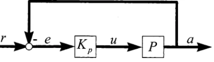
To achieve matched dynamic responses in high frequency range for high-speed operations, theoretical derivation and design prin-ciples of PMFBC is introduced here. Consider the N-axis motion control system, as shown in Fig. 1. The corresponding nomencla-ture is as follows:
1To whom correspondence should be addressed.
Contributed by the Dynamic Systems, Measurement, and Control Division of THE AMERICANSOCIETY OFMECHANICALENGINEERSfor publication in the ASME JOURNAL OFDYNAMICSYSTEMS, MEASUREMENT,ANDCONTROL. Manuscript received by the ASME Dynamic Systems and Control Division December 18, 2002. Associate Editor: J. Tu.
r⫽关r1r2¯ rn兴T, ri, i⫽1,¯,n: axial reference position com-mand
e⫽关e1e2¯ en兴T, ei, i⫽1,¯,n: axial position error u⫽关u1u2¯ un兴T, ui, i⫽1,¯,n: axial driving signal a⫽关a1a2¯ an兴T, ai, i⫽1,¯,n: actual axial position Kp⫽diag兵Kp1,Kp2,¯,Kpn其, Kpi, i⫽1,¯,n: position feedback controller of each axis
P⫽diag兵P1,P2,¯,Pn其, Pi, i⫽1,¯,n: controlled plant of each axis
T⫽diag兵T1,T2,¯,Tn其, Ti, i⫽1,¯,n: the position feedback system transfer function of each axis
The ith controlled axis Pi(z⫺1) of the position loop is parti-tioned as follows: Pi共z⫺1兲⫽Vi共z⫺1兲• 1 1⫺z⫺1⫽ z⫺1•Bia共z⫺1兲•Biu共z⫺1兲 Ai共z⫺1兲 • 1 1⫺z⫺1 where
Vi(z⫺1): the velocity loop
Ai(z⫺1): polynomials of the velocity loop with all poles Bia(z⫺1): polynomials of the velocity loop with acceptable stable zeros
Biu(z⫺1): polynomials of the velocity loop with unacceptable zeros共unstable and nearly unstable zeros兲
The position loop gain Li(z⫺1) of each axis is obtained as
Li共z⫺1兲⫽Kpi共z⫺1兲•Pi共z⫺1兲 (1) As shown in Fig. 1 and Eq.共1兲, matching frequency responses of the closed-loop position system Ti(z⫺1) implies that all the open-loop gains Li(z⫺1) are identical. To achieve matched frequency responses among all axes, the feedback controller Kpi(z⫺1) cor-responding to each axis is designed as
Kpi共z⫺1兲⫽␣共z⫺1兲• Ai共z⫺1兲 Bia共z⫺1兲•
兿
j⫽1 j⫽i n Buj 共z⫺1兲 (2) Thus, the open-loop gain Li(z⫺1) becomesLi共z⫺1兲⫽z⫺1•␣共z⫺1兲•
冉
兿
j⫽1 n Buj 共z⫺1兲冊
• 1 1⫺z⫺1 (3) where␣(z⫺1) is the controller with a design freedom embedded in the position feedback controller Kpi(z⫺1) to achieve the desired stability and performance of the systems.⌸j⫽1j⫽i
n
Bju(z⫺1) is con-volution of complementary zeros. By applying Eq.共3兲, the posi-tion feedback system transfer funcposi-tion of each axis Ti(z⫺1) be-comes
Ti共z⫺1兲⫽
Li共z⫺1兲 1⫹Li共z⫺1兲
(4) Equation共4兲 shows that the transfer functions of all axes Ti(z⫺1), i⫽1,¯,n are identical and thus the dynamic characteristics among all axes are perfectly matched. Although the matched dy-namic characteristics among all axes can be achieved by applying the present PMFBC as shown in Eq.共2兲, the order of controllers is unavoidably enlarged. In practice, it is preferable to reduce the order of controllers by adopting a lower-order model.
2.1 Design Example. To illustrate the proposed approach for perfectly matched design, feedback controllers are designed by applying the following velocity plants of a CNC machining center modeled as Vx共z⫺1兲⫽ ⫺0.0056z⫺1⫹0.0421z⫺2⫹0.1213z⫺3⫹0.0922z⫺4 1⫺0.1087z⫺1⫺0.3286z⫺2⫺0.1708z⫺3⫺0.1256z⫺4⫹0.0228z⫺5 (5) Vy共z⫺1兲⫽ ⫺0.0015z⫺1⫹0.0445z⫺2⫹0.1251z⫺3⫹0.0586z⫺4 1⫺0.236z⫺1⫺0.3909z⫺2⫺0.1736z⫺3⫺0.1012z⫺4⫹0.1616z⫺5 (6)
Three feedback controllers are designed as follows:
Case 共i兲 mismatched design 共mismatched兲. The proportional position controllers are designed to achieve a 0.707 damping ratio for each axis
Kpx⫽0.07 Kpy⫽0.1
Case 共ii兲 dc gain matched design 共matched dc gain兲. Feedback controllers are designed so that the position feedback loops are matched in the lower frequency range
Kpx⫽0.07 Kpy⫽0.0694
Case共iii兲 PMFBC. Feedback controllers are designed by applying the proposed method
␣⫽2.2⫻10⫺5 Kpx⫽ 2.2⫻10⫺5⫺6.742⫻10⫺4z⫺1⫺1.383⫻10⫺3z⫺2 ⫹3.744⫻10⫺4z⫺3⫹5.88⫻10⫺4z⫺4⫹3.323⫻10⫺4z⫺5 ⫹1.666⫻10⫺4z⫺6⫺3.301⫻10⫺5z⫺7 ⫺5.612⫻10⫺3 Kpy⫽ 2.2⫻10⫺5⫺1.702⫻10⫺4z⫺1⫺4.45⫻10⫺4z⫺2 ⫺1.886⫻10⫺4z⫺3⫹2.976⫻10⫺4z⫺4⫹2.441⫻10⫺4z⫺5 ⫹8.421⫻10⫺5z⫺6⫺4.021⫻10⫺5z⫺7⫺5.840⫻10⫺5z⫺8 ⫺1.486⫻10⫺3⫺8.904⫻10⫺4z⫺1
where␣ is simply chosen here to assure a suitable numerical order for the controlled axes. Frequency responses of cases共i兲–共iii兲 are shown in Figs. 2– 4, respectively. As shown in Fig. 2, the mis-matched design yields the worst contouring performance. Figure 3 shows that the matched dc-gain design in case共ii兲 achieves similar dynamic properties in the low frequency range corresponding to the slow motion speed. Moreover, PMFBC as shown in Fig. 4
achieves identical frequency responses among all axes and thus provides the best contouring accuracy in all speed operations.
2.2 Model Reduction. Although motion precision can be improved by applying the proposed PMFBC controllers, the pro-posed design algorithms also generally lead to higher-order con-trollers. In practice, model reduction methods can be applied to the redundant modes of controlled plants. In this paper, we use
balanced realization to remove the least observable and control-lable modes 关19兴. We thereby reduce the model of the velocity plant from fifth order to third order
Vx共z⫺1兲⫽ ⫺0.00437948z⫺1⫹0.04225802z⫺2⫹0.09618655z⫺3 1⫺0.88944678z⫺1⫹0.23980063z⫺2⫺0.19529895z⫺3 (7) Vy共z⫺1兲⫽ ⫺0.00141126z⫺1⫹0.04402946z⫺2⫹0.09340968z⫺3 1⫺0.83356582z⫺1⫺0.04295967z⫺2⫹0.03239339z⫺3 (8) The perfectly matched feedback controllers are designed as fol-lows:
Case 共iv兲 PMFBC with reduced-order plant model. Practical feedback controllers are designed by applying the proposed method and the reduced order model
␣⫽2.2⫻10⫺5 Kpx ⫽ 2.2⫻10⫺5⫺7.0594⫻10⫺4z⫺1⫺8.4038⫻10⫺4z⫺2 ⫹1.1262⫻10⫺3z⫺3⫺2.1513⫻10⫺4z⫺4⫹2.8438⫻10⫺4z⫺5 ⫺4.3794⫻10⫺3 Kpy ⫽ 2.2⫻10⫺5⫺2.3061⫻10⫺4z⫺1⫺3.0718⫻10⫺4z⫺2 ⫹4.1259⫻10⫺4z⫺3⫹1.3881⫻10⫺5z⫺4⫺1.5652⫻10⫺5z⫺5 ⫺1.4112⫻10⫺3
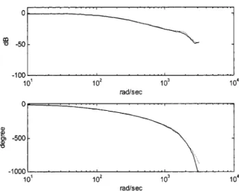
The frequency responses of the original and the reduced-order plant in the X axis are shown in Fig. 5. Results indicate that the approximation is satisfactory up to 1000 rad/s. Also, as shown in Fig. 6, the frequency responses of the biaxial system are virtually matched up to the same frequency of around 1000 rad/s. 3 DDOB Design
Theoretically, the perfectly matched feedback control provides contouring accuracy because of the matched dynamic properties among all axes. In real applications, motion precision is easily degraded by external disturbances and model uncertainty. Al-though DOB was developed to degrade the external disturbance effects, its implementation on computer-controlled processes is not direct and approximation is required. Moreover, available DDOB关14–16兴 cannot be directly applied to nonminimum phase
Fig. 2 Frequency responses of mismatched design, case„i…
„solid:Xaxis; dashed:Yaxis…
Fig. 3 Frequency responses of matched dc-gain design, case
„ii… „solid:Xaxis; dashed:Yaxis…
Fig. 4 Frequency responses of PMFBC, case „iii… „solid: X
axis; dashed:Yaxis…
Fig. 5 Frequency responses of the original„solid…and the re-duced order„dashed…plant
plant models which may exist in motion systems with discrete-time models关17,18兴. Therefore, a newly developed DDOB with a simple finite impulse response disturbance estimator which can be applied to nonminimum phase motion systems is proposed in this paper, As the present PMFBC is implemented in real applications, the DDOB is required to compensate for the undesired nonlieari-ties, model uncertainnonlieari-ties, and disturbances to maintain the matched dynamic responses for all axes.
Consider the new DDOB system as shown in Fig. 7, where u, ⑀, : reference input, driving force and velocity output of controlled plant, respectively
d, dˆ: external disturbance and estimated disturbance, respec-tively
␦ˆ : feedback signal : measured noise
N(z⫺1), D(z⫺1): numerator and denominator of plant, respec-tively
Nd(z⫺1): structure of external disturbance
Nn(z⫺1), Dn(z⫺1): numerator and denominator of nominal plant, respectively
Q(z⫺1): a low-pass filter
The velocity response of the controlled plant is derived as
⫽D共1⫺N N nQ兲⫹NDnQ u⫹ Nd共1⫺NnQ兲 D共1⫺NnQ兲⫹NDnQ d ⫺ NQDn D共1⫺NnQ兲⫹NDnQ ⫽ND 1 共1⫺NnQ兲⫹ N DDnQ u⫹Nd D 共1⫺NnQ兲 共1⫺NnQ兲⫹ N DDnQ d ⫺N D DnQ 共1⫺NnQ兲⫹ N DDnQ (9)
If the filter Q is designed such that Nn(z⫺1)Q(z⫺1)⫽1, Eq. 共9兲 becomes
⫽Nn Dn
u⫺
On the other hand, if the filter Q is designed such that Nn(z⫺1)Q(z⫺1)⫽0, Eq. 共9兲 becomes
⫽NDu⫹Nd D d Therefore, the filter Q is designed as
再
Nn共z⫺1兲Q共z⫺1兲⫽1, in the lower frequency region Nn共z⫺1兲Q共z⫺1兲⫽0, in the higher frequency region(10) to degrade external disturbances and reject measurement noise. The design of the filter Q depends greatly on the nominal numera-tor Nn(z⫺1). It contains the following three steps:共1兲 stable pole-zero cancellations,共2兲 an all-pass filter, and 共3兲 an embedded low-pass filter.
To obtain the stable pole-zero cancellation, the nominal nu-merator Nn(z⫺1) is separated Nn共z⫺1兲⫽Nn a共z⫺1兲N n u共z⫺1兲 where
Nna(z⫺1): an acceptable polynomial with stable roots. Nn
u
(z⫺1): an unacceptable polynomial with unstable and nearly unstable roots.
Suppose the unacceptable polynomial Nn u (z⫺1) is represented as Nn u共z⫺1兲⫽b1z⫺1⫹b2z⫺2⫹¯b mz⫺m ⫽z⫺m共b 1zm⫺1⫹b2zm⫺2⫹¯bm兲⫽z⫺m•Nˆn u共z兲
Then, design of the filter Q is
Q共z⫺1兲⫽ 1 Nn a共z⫺1兲•关Nˆ n u共z兲兴*•LPF共z ⫺1兲 (11)
where关•兴*denotes the complex conjugate operator and 关Nˆn
u共z兲兴*⫽共b
1z⫺共m⫺1兲⫹b2z⫺共m⫺2兲⫹¯bm兲 (12)
Fig. 6 Frequency responses of the PMFBC with the reduced-order plants
Equation共12兲 is stable and realizable, and兵Nn u
(z⫺1)/关Nˆn u
(z)兴*其 forms a stable all-pass filter. The low-pass filter LPF(z⫺1) can be designed such that
Q共z⫺1兲•Nn共z⫺1兲⫽ Nn u共z⫺1兲 关Nˆn u共z兲兴*•LPF共z ⫺1兲
possesses the desired frequency response as given in Eq.共10兲. The stability of the DDOB, as shown in Fig. 7, can be proved by the following lemma
3.1 Lemma. Define the equivalent plant R as
R⫽Dn• N D⫺Nn
and the equivalent feedback system S as shown in Fig. 8. Then, the DDOB as shown in Fig. 7 is internally stable if the equivalent feedback system S is internally stable.
Proof: Since
共1兲 system S is internally stable implies that Q(z⫺1), R(z⫺1),
and关1/1⫹Q(z⫺1)R(z⫺1)兴 are all stable, and
共2兲 all subsystems of DDOB,兵Nd,N,1/D,Nn,Dn,Q其, are all stable, the DDOB is thus internally stable.
According to the lemma, system stability directly depends on the filter Q and thus the low-pass filter LPF(z⫺1) in filter Q must be designed to achieve both desired stability and frequency re-sponses. However, as shown in Eq.共9兲, if
Nn共z⫺1兲⫽N共z⫺1兲 and Dn共z⫺1兲⫽D共z⫺1兲, the velocity response is
⫽NDu⫹Nd D 共1⫺NQ兲 1 d⫺ NQ 1 ,
and the stability is dominated by the denominator D(z⫺1) and the filter Q(z⫺1). It implies that the design of the filter Q(z⫺1) does not affect the stability of the DDOB if the filter Q(z⫺1) is stable. Furthermore, the equivalent plant R in Fig. 8 also shows that the design of filter Q may be invalid when the nominal plant model Nn/Dnis significantly different from the real plant N/D.
3.2 Design Example. The nominal plant Nn/Dnis chosen to be the reduced-order model of the velocity loop as shown in Eqs.共7兲–共8兲. Therefore, the DDOB is designed as
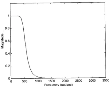
Case 共v兲 perfectly matched feedback control design with DDOB共PMFBC⫹DDOB兲. To achieve stable system he filter Q is designed as Qx共z⫺1兲⫽ 0.00497194⫹0.024859747z⫺1 ⫹0.04971949z⫺2⫹0.04971949z⫺3 ⫹0.02485974z⫺4⫹0.00497194z⫺5 1⫺2.94719898z⫺1⫹3.23989221z⫺2 ⫺1.20983151z⫺3⫺0.4541163z⫺4⫹0.52748002z⫺5 ⫺0.14373367z⫺6⫹0.00883831z⫺7 Qy共z⫺1兲⫽ 0.00511975⫹0.02559877z⫺1⫹0.05119755z⫺2 ⫹0.05119755z⫺3⫹0.02559877z⫺4⫹0.00511975z⫺5 1⫺2.91517429z⫺1⫹3.16186245z⫺2⫺1.1599981z⫺3 ⫺0.41974012z⫺4⫹0.46329684z⫺5 ⫺0.11089379z⫺6⫹0.00293275z⫺7
Figure 9 shows the frequency response of Q(z⫺1)Nn(z⫺1) for the X axis with a bandwidth of 500 rad/s which is suitable for the velocity loop around 100 Hz bandwidth.
4 The Feedforward Control Design
Although perfectly matched dynamic characteristics among all axes can be achieved by applying the PMFBC and the external disturbance can be significantly reduced by applying the DDOB to achieve improved the contouring accuracy, the servo lag effect should be minimized to improve the tracking accuracy of multi-axis motion systems. Therefore, the common feedforward control-ler for motion systems, the ZPETC proposed by Tomizuka can be suitably employed关2兴. Consider the control systems with two de-grees of freedom as shown in Fig. 10. The corresponding nomen-clature is listed later
rf⫽关rf 1rf 2¯ rf n兴T, rf i, i⫽1,¯,n: the filtered axial refer-ence position command
F⫽diag兵F1,F2,¯,Fn其, Fi, i⫽1,¯,n: the ZPETC designed feedforward control for each axis
Suppose the position feedback loop transfer function Ti(z⫺1) is represented as Ti共z⫺1兲⫽ ai共z⫺1兲 rf i共z⫺1兲 ⫽z⫺diBi共z⫺1兲 Ai共z⫺1兲 ⫽z ⫺diB a i共z⫺1兲B u i共z⫺1兲 Ai共z⫺1兲 (13) where
z⫺di:di delay of ith axis position feedback loop Ai(z⫺1): denominator of ith axis position feedback loop Bi(z⫺1): numerator of ith axis position feedback loop
Fig. 8 The equivalent feedback loop system
Fig. 9 The designed frequency response ofQ„zÀ1…N n„zÀ1…
Ba i
(z⫺1): polynomials with acceptable zeros Bui(z⫺1): polynomials with unacceptable zeros
Note that the optimal ZPETC关5兴 further improves tracking per-formance. The designed feedforward controller Fi is in the fol-lowing form: Fi共z⫺1兲⫽
冉
兺
k⫽0 N⫺P ␣k•共z k⫹z⫺k兲冊
•冉
Bu i共z兲 Bu i共1兲2冊
•冉
zdiAi共z⫺1兲 Ba i共z⫺1兲冊
(14) Design Example. The hybrid structure which combines共a兲 perfectly matched feedback control,共b兲 the optimal ZPETC, and 共c兲 the DDOB, is designed to improve both tracking and contour-ing accuracy in multi-axis motion systems. Because of model un-certainty in the higher frequency region, the bandwidth is chosen around 500 rad/s in design.Case共vi兲 hybrid structure 共hybrid兲. The feedforward controller is designed with optimal ZPETC关5兴 given as
F共z⫺1兲⫽ 0.99518942z7⫺6.40810113z6⫹18.04061216z5 ⫺3.28244714z4⫺11.2545723z3⫹1.29958907z2 ⫹1.11190473z1⫹0.29919024⫹0.27312898z⫺1 ⫺0.07579595z⫺2⫺0.00750972z⫺3⫹0.00980315z⫺4 ⫺0.00101341z⫺5⫹0.00002189z⫺6 1
Figure 11 shows the frequency response of feedforward con-trolled system. The figure indicates that unity-gain region falls within关0, 785 rad/s兴. The hybrid control is obtained by adding the feedforward controller F to the PMFBC⫹DDOB. Because the DDOB is designed under the frequency condition as shown in Eq. 共10兲, the design of the optimal ZPETC depends heavily on the bandwidth of Q(z⫺1)Nn(z⫺1). With the decrease in uncertainty obtained by applying the feedback control, the optimal ZPETC can be designed to make the unity gain region cover the band-width of Q(z⫺1)Nn(z⫺1) as shown in Figs. 9 and 11.
Basically, the proposed design by integrating PMFBC, DDOB, and ZPETC are independent. The feedback loop of PMFBC for all axes should be designed in the first step. Then, the DDOB is designed for each axis so that the matched dynamic responses of PMFBC can be well maintained. Finally, the feedforward control ZPETC is directly included. Thus, not only both contouring and
tracking accuracy can be improved by applying PMFBC and ZPETC, respectively, the proposed hybrid control structure is also robust because of the inclusion of DDOB.
5 Experimental Results
5.1 Experimental Setup. The experimental setup of the DYNA 1007 CNC machining center is the same as in Ref.关20兴. A PC-486 generated the main control commands and recorded the principle signals including: the input command calculation for dif-ferent contours, the implementation of controller, and the control
Fig. 11 The frequency response of the feedforward controlled system
Fig. 12 Experimental results for design with mismatched gains case„i…
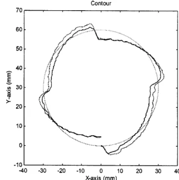
Fig. 13 Experimental results for matched dc-gain „case „ii…, dashed…and PMFBC„case„iii…, solid…
Fig. 14 Experimental results for PMFBC„case„iv…, solid…and
PMFBC¿DDOB„case„v…, dashed… Fig.„case15„vi…, solidExperimental… results for PMFBC¿DDOB¿ZPETC
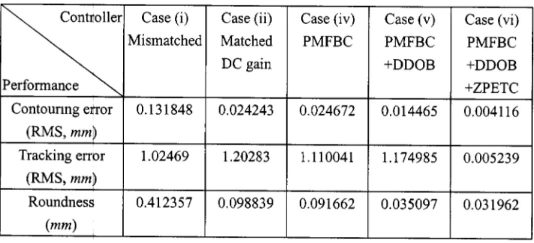
Table 1 Experimental results with a high-speed circular com
inputs to the velocity loop. The machine feed system is driven by scanning electron microscopy alternating current servo motors. The PC-486 interface utilized an AD/DA card to send and receive the control inputs and position outputs respectively at a sampling period of 1 ms.
A circular contour command with a radius of 30 mm and a linear contour command with a 45 deg incline angle were applied with a high speed of 5 m/min and a low speed of 600 mm/min. Note that 5 m/min is the highest speed of the DYNA CNC ma-chining center, and that speeds of around 600 mm/min are com-mon for fine machining process.
5.2 Results and Discussions. Experimental results for the different control structures under different speed operations as the
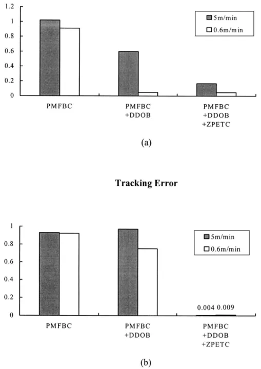
command 5 and 0.6 m/min are shown in Figs. 12–15 and sum-marized in Tables 1 and 2, respectively. For linear commands with different speeds, tracking errors are shown in Fig. 16 and Tables 3 and 4. All experimental results indicate that both the matched dc-gains design and PMFBC design significantly reduces contour-ing error compared with the mismatched design as shown in Figs. 12 and 13. Furthermore, results for PMFBC and its integration with the DDOB and the ZPETC are normalized to the results for the matched dc-gains design as summarized in Figs. 17 and 18. The merits of the proposed control structure by integrating PM-FBC, DDOB, and ZPETC can be clearly indicated as in Tables 1– 4 as follows:
1. The proposed PMFBC design results in matched dynamic
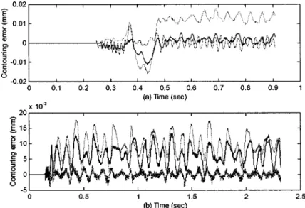
Fig. 16 Experimental results with linear commands„a…high speed,„b…low speed„solid: PMFBC, dashed: matched dc-gain, dashdot: PMFBC¿DDOB
¿ZPETC…
Table 3 Experimental results with a high-speed linear com
responses for all axes within a higher frequency range compared to matched dc-gain control. Therefore, experimental results of PMFBC also lead to meaningful reduction of contouring accuracy in linear motion especially in the case of high-speed operation as in Tables 3 and 4共case iv兲.
2. Note that the application of PMFBC共case iv兲 does not ren-der satisfactory improvement in circular contouring as in Tables 1 and 2. Figure 13 shows that the nonlinear slip-stick phenomenon is still significant, because PMFBC is mainly a linear model-based control design. By introducing the DDOB to compensate for the undesirable properties, results as shown in Tables 1 and 2共case v兲
and Fig. 14 indicate that the contouring accuracy is then greatly improved, especially in the case of low-speed operation where the friction becomes more dominant.
3. Matched dc-gain control and PMFBC generally improves the contouring accuracy as in Tables 1– 4共case ii兲. However, their tracking accuracy is merely improved. By including the feedfor-ward control ZPETC in the proposed PMFBC structure, both the tracking error and contouring error are thus further reduced共case vi兲. Note that applications of the ZPETC only does not render improvement in contouring accuracy关13兴.
6 Conclusion
In practice, mismatched frequency responses among axes seri-ously degrade contouring performance, especially under high-speed operations. The proposed PMFBC design leads to perfectly matched frequency responses among all axes and thereby achieves highly accurate contouring. Moreover, because the model-based PMFBC design is sensitive to nonlinearity, external disturbances, and plant uncertainty, a new DDOB was developed in this paper for nonminimum phase discrete-time systems. Furthermore, we have shown that the feedforward controller ZPETC can be di-rectly applied to further reduce the tracking error. The feasibility
of the present design has also been proven by using a reduced-order model. Experimental results on a CNC machining center show that the proposed control structure significantly improves both contouring and tracking performance for precise multi-axis motion systems under high-speed operations.
Acknowledgment
This work was supported by the National Science Council, Re-public of China, under Contract No. NSC 89-2212-E-009-018. Fig. 18 Normalized errors for linear commands
References
关1兴 Poo, A., Bollinger, J. G., and Younkin, W., 1972, ‘‘Dynamic Error in Type
Contouring Systems,’’ IEEE Trans. Ind. Appl., 8共4兲, pp. 477–484.
关2兴 Tomizuka, M., 1987, ‘‘Zero Phase Error Tracking Algorithm for Digital
Con-trol,’’ ASME J. Dyn. Syst., Meas., Control, 109„1…, pp. 65–68.
关3兴 Tsao, T. C., and Tomizuka, M., 1994, ‘‘Robust Adaptive and Repetitive Digital
Tracking Control and Application to A Hydraulic Servo for Noncircular Ma-chining,’’ ASME J. Dyn. Syst., Meas., Control, 116共1兲, pp. 24–32.
关4兴 Xia, J. Z., and Menq, C. H., 1995, ‘‘Precision Tracking Control of
Nonmini-mum Phase Systems With Zero Phase Error,’’ Int. J. Control, 61共4兲, pp. 791– 807.
关5兴 Yeh, S. S., and Hsu, P. L., 1999, ‘‘An Optimal and Adaptive Design of the
Feedforward Motion Controller,’’ IEEE/ASME Trans. Mechatronics, 4共4兲, pp. 428 – 439.
关6兴 Koren, Y., 1980, ‘‘Cross-Coupled Biaxial Computer for Manufacturing
Sys-tems,’’ ASME J. Dyn. Syst., Meas., Control, 102共4兲, pp. 265–272.
关7兴 Kulkarni, P. K., and Srinivasan, K., 1990, ‘‘Cross-Coupled Control of Biaxial
Feed Drive Servomechaniasms,’’ ASME J. Dyn. Syst., Meas., Control, 112共2兲, pp. 225–232.
关8兴 Chuang, H. Y., and Liu, C. H., 1991, ‘‘Cross-Coupled Adaptive Feedrate
Con-trol for Multiaxis Machine Tools,’’ ASME Trans. J. Dyn. Syst., Meas., ConCon-trol,
113共3兲, pp. 451–457.
关9兴 Jee, S., and Koren, Y., 1995, ‘‘A Self-Organizing Fuzzy Logic Control for
Friction Compensation in Feed Drives,’’ Proceedings 1995 ACC, Seattle, pp. 205–209.
关10兴 Lo, C. C., 1998, ‘‘Three-Axis Contouring Control Based on a Trajectory
Co-ordinate Basis,’’ JSME Int. J., Ser. C, 41共2兲, pp. 242–247.
关11兴 Chiu, G. T. C., and Tomizuka, M., 1995, ‘‘Contouring Control of Machine
Tool Feed Drive Systems: A Task Coordinate Frame Approach,’’ ASME J. Dyn. Syst., Meas., Control, 117共1兲, pp. 503–510.
关12兴 Cheng, C. C., Chen, C. Y., and Chiu, G. T. C., 2002, ‘‘Predictive Control With
Enhanced Robustness for Precision Positioning in Frictional Environment,’’ IEEE/ASME Trans. Mechatronics, 7共3兲, pp. 385–392.
关13兴 Yeh, S. S., and Hsu, P. L., 1999, ‘‘Analysis and Design of the Integrated
Controller for Precise Motion Systems,’’ IEEE Trans. Control Syst. Technol.,
7共6兲, pp. 706–717.
关14兴 Endo, S., Tomizuka, M., and Hori, Y., 1993, ‘‘Robust Digital Tracking
Con-troller Design for High-Speed Positioning Systems,’’ Proceedings 1993 ACC, San Francisco, pp. 2494 –2498.
关15兴 Lee, H. S., and Tomizuka, M., 1996, ‘‘Robust Motion Controller Design for
High-Accuracy Positioning Systems,’’ IEEE Trans. Ind. Electron., 43共1兲, pp. 48 –55.
关16兴 Kempf, C. J., and Kobayashi, S., 1999, ‘‘Disturbance Observer and
Feedfor-ward Design for a High-Speed Direct-Drive Positioning Table,’’ IEEE Trans. Control Syst. Technol., 7共5兲, pp. 513–526.
关17兴 Astrom, K. J., Hagander, P., and Sternby, J., 1984, ‘‘Zeros of Sampled
Sys-tems,’’ Automatica, 20共1兲, pp. 31–38.
关18兴 Clarke, D. W., 1984, ‘‘Self Tuning Control of Nonminimum Phase Systems,’’
Automatica, 20共5兲, pp. 501–517.
关19兴 Samar, R., Postlethwaite, I., and Gu, D. W., 1995, ‘‘Model Reduction With
Balanced Realization,’’ Int. J. Control, 62共1兲, pp. 33–64.
关20兴 Yeh, S. S., and Hsu, P. L., 1999, ‘‘Estimation of the Contouring Error Vector
for the Cross-Coupled Control Design,’’ IEEE/ASME Trans. Mechatronics,