This article was downloaded by: [National Chiao Tung University 國立交通大學]
On: 28 April 2014, At: 00:23
Publisher: Taylor & Francis
Informa Ltd Registered in England and Wales Registered Number: 1072954 Registered office: Mortimer House,
37-41 Mortimer Street, London W1T 3JH, UK
Tribology Transactions
Publication details, including instructions for authors and subscription information:
http://www.tandfonline.com/loi/utrb20
A Mixed Lubrication Model for Computer Simulation of
Extrusion Processes
Tze-Chi Hsu
a, Yuan-Mo Li
a& Ching-Hua Hung
ba
Yuan Ze University, Department of Mechanical Engineering , Chung-Li, Taiwan
b
National Chia-Tung University, Department of Mechanical Engineering , Hsin-Chu, Taiwan
Published online: 25 Mar 2008.
To cite this article: Tze-Chi Hsu , Yuan-Mo Li & Ching-Hua Hung (2000) A Mixed Lubrication Model for Computer Simulation of
Extrusion Processes, Tribology Transactions, 43:4, 781-787, DOI:
10.1080/10402000008982408
To link to this article:
http://dx.doi.org/10.1080/10402000008982408
PLEASE SCROLL DOWN FOR ARTICLE
Taylor & Francis makes every effort to ensure the accuracy of all the information (the “Content”) contained
in the publications on our platform. However, Taylor & Francis, our agents, and our licensors make no
representations or warranties whatsoever as to the accuracy, completeness, or suitability for any purpose of the
Content. Any opinions and views expressed in this publication are the opinions and views of the authors, and
are not the views of or endorsed by Taylor & Francis. The accuracy of the Content should not be relied upon and
should be independently verified with primary sources of information. Taylor and Francis shall not be liable for
any losses, actions, claims, proceedings, demands, costs, expenses, damages, and other liabilities whatsoever
or howsoever caused arising directly or indirectly in connection with, in relation to or arising out of the use of
the Content.
This article may be used for research, teaching, and private study purposes. Any substantial or systematic
reproduction, redistribution, reselling, loan, sub-licensing, systematic supply, or distribution in any
form to anyone is expressly forbidden. Terms & Conditions of access and use can be found at
http://
www.tandfonline.com/page/terms-and-conditions
xed Lubrication Model for Computer Simulation of
Extrusion ~ r o c e s s e s ~
TZE-CHI H S U and Y U A N - M O L I
Yuan Ze University
Department of Mechanical Engineering Chung-Li, Taiwan
and CHING-HUA H U N G National Chia-Tung University Department of Mechanical Engineering
Hsin-Chu, Taiwan
A mixed lubricationljiriction model for extrusion process is pressure under different lubrication conditions are compared with developed in the present research. The model combines a rigid- experimental investigation. The discrepancy is very small and the plasticity finite element code to simulate the interface condition proposed model proved to be very eficienr in predicting interface between the tooling and workpiece in the extrusion operation. The friction condition in the extrusion processes.
influence of surface roughness on lubricant flow is treated by
using the average Reynolds equation. The active lubrication KEY WORDS
regime and appropriate friction factor were determined from the Mixed Lubrication; Finite Element Method; Surface
current local values of interface variables such as mean lubricant Roughness
film thickness and workpiece and tooling roughness, in addition to
the more traditional external variables such as interface pressure, INTRODUCTlON
node sliding veloci9 and strain rate of the workpiece. Numerical Friction and lubrication are of great importance in metal form-
the coupled code include friction stress and ing operations. In most cases minimizing friction is beneficial since it reduces the force and energy required for a given opera- Final manuscript approved February 16,2000 tion. This will lessen the stresses imposed o n tooling and prevent direct metal-to-metal contact which contributes t o longer tooling life and better quality control. Too thick a lubricant film will also result in a matt surface d u e t o insufficient constraint by the tool-
NOMENCLATURE x = the distance to the apex of tooling
X~ = the distance of contact edge to the apex of tooling
A = fractional contact area I2 = the distance of outlet edge to the apex of tooling
C~ = adhesion coefficient Y = pressure coefficient of the viscosity
E = nondimensional strain rate E = bulk strain rate
H = nondimensional film thickness 13 = semi-die angle
no = nondimensional effective hardness 61 = mean slope of tooling asperities
4
= average asperity length P = lubricant viscosity at pressure pS = nondimensional velocity Po = lubricant viscosity at atmospheric pressure
U = velocity of the workpiece (T = composite surface roughness
u1 = velocity of the workpiece at the contact edge a! = surface roughnesses of sheet (Rq values)
u2 = velocity of the workpiece at the outlet edge a, = surface roughnesses of tooling (Rq values)
= velocity of the tooling
?Z = adhesive shear stress
h = lubricant film thickness
5
= friction stressh1 = lubricant film thickness at the edge of contact Zh = hydrodynamic friction stress
4
= shear strength of the workpiece r~ = plowing friction stressP = interface pressure
3
' = shear stress factorpa = contact pressure of the asperity @S = shear flow factors
P h = lubricant pressure $X = pressure flow factors
4 = extrusion pressure
T. Hsu. Y. L i AND C. HUNG
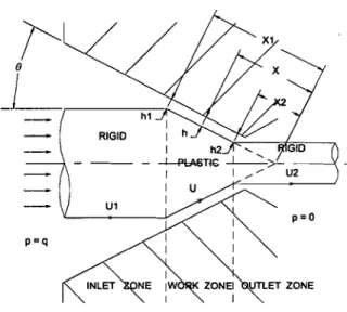
Fig. 1-schematic view of extrusion process.
ing. Therefore n careful design of a lubrication system to achieve
:I suitable friction level is essential for a successful metal forming
operation ( I ) .
The finite eletnent method has been proved to be the most effi- cient computational scheme in the computer-based simulation of metal forniing processes ( 2 ) . This method accurately simulates the flow of metal during the forming operation and provides the great- est amount of itiformation about the process ( 3 ) . Despite the advances possible through finite element modeling of the forming process, one problem which has not been resolved satisfactorily involves modeling of the frictional stresses at the toolingJwork- piece interface. One way of defining interface conditions in metal working has relied, to a large extent, on measurements of tool loads or tangential forces from which average friction coefficients could be obtained. S o ~ n e theoretical simple friction models are also commonly used it1 describing the interface friction condition
between the tooling and workpiece such as the Amontons- Coulomb law and constant friction factor. However, it has been pointetl out that these simple friction models are not capable of describing the contact phenomenon between the tooling and workpiece due to large plastic deformation ( 4 ) . This greatly limits the usefulness of simulation as a design tool. More realistic fric- tion ~iiodcls must take account of the fundamental processes i~ivolved in friction and lubrication at the tooling/workpiece inter- face.
As n first attempt to realistically implement friction in metal forming operations, Hsu and Wilson (5) and Wilson, et al. (6)
tlevelopcd a friction model in lubricated sheet-metal forming. Friction is expressed in terms of internal interface variables (mean lubrictuit film thickness, sheet roughness and tooling roughness) in atlditio~i to the more traditional external variables (interface pressure, sliding speed and strain rate). The new model was cou- pled with a finite element code and applied to an axisymmetric stretch forming operation. Numerical results using the coupled codes showed excellent agreement with measured strain distribu-
tion over a range of operation conditions. Hsu and Lee (7), (8) and Hsu, et al. (9) analyzed the simple upsetting operation and rolling process by using the same strategy and the predictions from the model such as the distribution of the friction stress and normal pressure showed good correlation compared with the experimen- tal measurements.
The present paper describes the development of a more realis- tic friction model for use in the computer simulation of extrusion processes. The friction model spanning the full range of lubrica- tion regimes treats the influence of surface roughness on lubricant flow and on asperity contact. The mean lubricant film thickness is calculated by using the average flow model derived by Patir and Cheng ( I O ) , (11). In dealing with the mechanics of asperity con- tact, the boundary model proposed by Wilson and Sheu (12), (13)
is adopted in which the joint plastic deformation of surface asper- ities is considered. The computer simulation of extrusion process- es is then conducted by incorporating the realistic friction model to a rigid-plasticity finite element code. Several experimental data are used to check the validity of the proposed model. The distri- bution of the friction stress and normal pressure between the workpiece and tooling are investigated. The results of computer simulation agree well with the experimental data.
LUBRICATION ANALYSIS
The process wherein a thick film lubrication model is pre- scribed was derived by Wilson and Walowit (14) and is shown in Fig. I. A cylindrical billet is extruded through a conical die under
the action of an extrusion pressure q. The product emerges into a space at zero pressure. No draw force or augmentation force is applied to the workpiece. The interface between the tooling and workpiece may be divided into three regions : the inlet zone, the work zone and the outlet zone. The lubricant is drawn into the space between the rigid workpiece and tooling in the inlet zone. The pressure in the lubricant builds up rapidly until it reaches the yield pressure of the workpiece at the inlet edge of the work zone. The workpiece deforms plastically in the work zone and the lubri- cant is carried along by the workpiece motion until it reaches the outlet zone. In the outlet zone the workpiece again becomes rigid and the lubricant film pressure falls to zero.
The average Reynolds equation ( l o ) , (11) in the one dimension can be expressed as
where h is the lubricant film thickness and U is the average veloc- ity of the workpiece and tooling. The hydrodynamic pressure is denoted as p and the composite surface roughness o is defined as
and o, and o2 are the surface roughness of the tooling and work- piece, respectively. @, and
Qs
are the pressure flow and shear flow factors which compensate for the effect of roughness and may be expressed as functions of h ando.
If the roughness are isotropicA Mixed Lubrication Model for Computer Simulation of Extrusion Processes
the authors may use the simple expressions provided by Tripp
(15).
In the full film regime in which the lubricant film thickness is larger than three times of the composite surface roughness, Eqs. [9] and [I21 can be used to calculate the film thickness between the tooling and workpiece. However such a condition in which the tooling is completely separated from the workpiece by a thin film of liquid lubricant is relatively rare in practice. The mixed regime in which the load is supported both by the pressurized lubricant film and asperity contact can thus be thought of as "general cases" dealing particularly with the conditions of most practical interest. The load sharing process can be expressed as
The viscosity of the lubricant p is assumed as Newtonian and governed by
where p, is the viscosity at atmospheric pressure and y is the pres- sure coefficient of viscosity.
Since the lubricant film thickness is small compared with the diameter of the workpiece, the film thickness in the inlet zone as shown in Fig. 1 is assumed as
in which p, is the total interface pressure, A is the nondimension-
al contact area, pa is the average asperity contact pressure and p, is the hydrodynamic pressure. An approximation for A is proposed from Christensen (16).
where x, is the distance from the inlet edge of the work zone to the apex of the tooling and h, is the film thickness at the inlet edge of the work zone. Since the pressure gradient in the work zone is so small that its effect on the lubricant flow may be neglected, the pressure gradients in the inlet and outlet zones are assumed to become zero at the edge of the work zone. The boundary condi- tions are
and
x = x,, h = h,, p = pl and dp/dx =
o
[71Wilson and Sheu (12) developed a semi-empirical equation to calculate the effective hardness of the workpiece subjected to plastic deformation and it can be written as
The inlet zone analysis involves the integration of the average Reynolds Eq. [I] with the film thickness giver by Eq. [6]. After applying the boundary conditions given in Eqs. [7] and
[a],
the governing equation of the inlet film thickness is expressed asand
where
U I
is the velocity of workpiece at the inlet edge andThe effective hardness of workpiece Ha can be also expressed as
and
oo = 0: -0;
Since the pressure gradient in the work zone is assumed to be zero, the distribution of the film thickness in the work zone can then be obtained as
in which kS is the material shear strength. The nondimensional strain rate E is denoted as
T. HSU, Y. LI AND C. HUNG
I - A
E = -
S
and S is the nondimensional velocity which can be written as
L, is the average half spacing of the asperity, 8, is the average slope of the asperity, U, is the velocity of the tooling and the
strain rate of the workpiece is denoted as ~3
.
The lubricant film thickness in the mixed lubrication regime is calcul:~ted by using a numerical scheme. It assumed an initial film thickness which is less than three times of the composite surface roughness first, and the hydrodynamic pressure and contact area can thus be evaluated from Eqs. [9] and [14], respectively. The asperity contact pressure is then determined from Eqs. [16] to [21] from which the nondimensional strain rate E is calculated using pertinent external variables by finite element analysis. The algo- rithm is repeated by adjusting the film thickness until Eq. [13] is satisfied.
FRICTION MODEL
Friction stress is most commonly characterized by the active lubrication regime at the interface. Generally, it consists of three parts and can be written as
where z,, z, and z,, are the adhesion, plowing and viscous friction stress, respectively. The viscous resistance to lubricant shear z,, is the dominant friction stress in the full film regime since contact area A equals to zero and can be expressed as
The shear stress factor
$f
is a correction for surface roughness which is defined by Ref. (15) and can be written asand
In the mixed lubrication regime, where the average film thick- ness is smaller, some asperity contacts are established and the adhesion and plowing components are given by
7, = caks [291
which C, is the adhesion coefficient.
RESULTS AND DISCUSSION
A number of test runs have been made using the proposed lubrication/friction model coupled to the rigid plasticity FEM code to investigate the performance of this approach. A simple two-dimensional FEM code, called ALPID (Analysis of Large Plastic Increment Deformation), written for metal-forming simu- lation by Kobayashi (3) is used. It is based on rigid viscoplastic finite-element formulation and also valid for rigid plastic materi- al. One hundred and eighty elements were used in the finite ele- ment mesh as shown in Fig. 2. The parameters calculated from the FEM code such as contact pressure and surface velocity were transformed into the lubrication/friction model to determine the local lubricant film thickness. These variables were then com- bined to evaluate the local friction which was passed back to the FEM code. The basic strategy was outlined in Ref. (6).
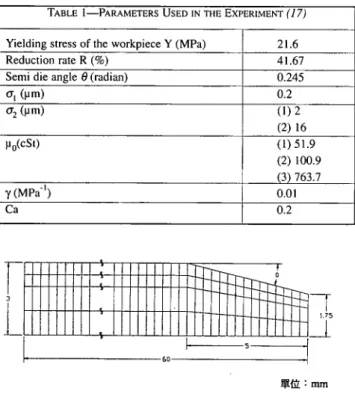
The experiments were conducted by Huang and Lu (I 7) and a semi-die angle of 14.036 degree were prepared. The assembly of the die contains the upper mold plate, ram, extrusion ring, cover plate, and the lower mold plate. The ram is attached to the upper mold plate and the workpiece is positioned at the entrance of the die at the beginning of the experiment. The surface profile of the die and workpiece are measured and the geometric quantities such as the half spacing and mean slope of the asperities can then be calculated from the profile by using the stylus instrument. Three different lubricants which range from high viscosity to low vis- cosity are chosen to apply at the interface between the workpiece and the die. The upper mold plate is then driven by hydraulic power with a constant speed 3.5 mmlsec to push the workpiece through the extrusion ring. Those variables used in the experi- ments are listed in the Table 1.
Figure 3 compares values of the normal force calculated from the coupled code with the experiments. The comparison of the friction force is shown in Fig. 4. It is evident that increasing the lubricant viscosity tends to reduce the normal force and friction force between the tooling and workpiece. The results of current simulation agree well with the experiments. The discrepancy could be caused by the determination of the experiment parame- ters such as pressure coefficient of the lubricant and adhesion coefficient.
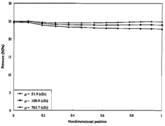
The distribution of the normal pressure and friction stress in the work zone are shown in Figs. 5 and 6, respectively. The cor- responding estimated lubrication regime along the work zone is shown in Fig. 7. All the three lubricants, high viscosity to low vis- cosity lubricant, produced a single mixed lubrication regime in the work zone. The nondimensional film thickness is between 1.2 to
1.8 which is less than the normal value of three. The magnitude of
friction stress depends on the nondimensional film thickness.
A Mixed Lubrication Model for Computer Simulation of Extrusion Processes
Fig. 2-The finite element mesh of the simulation.
TABLE 1-PARAMETERS USED IN THE EXPERIMENT (1 7)
Lower nondimensional film thickness tends to cause higher fric- tion stress and lower normal pressure. The variation caused by the film thickness is much more apparent in the friction stress distri- bution than in the normal pressure distribution. .
Another important parameter which will affect the interface condition is surface roughness. The influence of surface rough- ness of the workpiece on the distribution of normal pressure and friction stress are shown in Figs. 8 and 9, respectively. It can be expected that rougher surface will produce a higher friction situa- tion. The surface roughness effect on the normal pressure distri- bution is not as apparent as in the friction distribution. Their cor- responding estimated lubrication regime is shown in Fig. 10. The nondimensional film thickness is the ratio between the lubricant film thickness and the composite surface roughness. The mixed lubrication regime which is defined as the nondimensional film thickness less than three is prevailed along the workzone. The angle between the workpiece and tooling is also very crucial in designing the extrusion operation. It is common to select an angle which will require less entry pressure and it can be determined by Fig. 11 for various lubricants.
Yielding stress o f the workpiece Y (MPa) Reduction rate R (%)
Semi die angle 8 (radian)
0, (pm) 0, (pm) po(cSt) ( M P ~ . ' ) Ca CONCLUSIONS 21.6 4 1.67 0.245 0.2 (1) 2 (2) 16 (1) 51.9 (2) 100.9 (3) 763.7 0.01 0.2
The simulation combines a rigid-plasticity finite element code with a lubrication analysis and friction model. The surface rough- ness effect on lubricant flow is included by using an average Reynolds equation. The local values of roughness and film thick- ness were then combined to decide the active lubrication regime at each location and increment within the workpiece/tooling inter- face. A friction model appropriate to the regime then provided an estimate of friction for use in the evolving plasticity solution. The distributions of normal force and friction force predicted by the
Fig. 3--Variation of the normal force for different lubricant with a, =
2pm.
Fig. 4--Variation of the friction force for different lubricant with a, = 2pm.
proposed model can be used to design the tooling and choose the suitable manufacturing parameters.
On the experimental side, it would be valuable to conduct more experiments to help verify and refine the existing model. The inclusion of thermal effect will definitely improve the sensi- tivity and accuracy of the current code. Work is in progress in each of these areas.
ACKNOWLEDGMENTS
The authors wish to thank the National Science Council for the financial support of this research by Grant No. NSC86-2212-E- 155-002.
REFERENCE
( I ) Wilson, W. R. D., "Friction and Lubrication in Bulk Metal-Forming Processes,"
Jour. Applied Metalworking, 1 , pp 7-19, (1979).
(2) Zienkiewicz, 0. C., The Finite Element Method, McGraw-Hill Book Co. (UK) Ltd., London, (1997).
(3) Kobayashi, S., Oh, S. I. and Altan, T., "Metal Forming and the Finite Element Method," Oxford University Press, Oxford, 1989.
(4) Wilson, W. R. D., "Mixed Lubrication in Metal Forming," Advanced Techr~ology
of Plasticity, pp 1667-1675, (1990).
786
T. Hsu,Y.
LI ANDC.
HUNGFig. 5--The dlstributlon of normal pressure i n the work zone.
Fig. &The distributlon of friction stress i n the work zone.
+ p a 763.7 (eS1)
I
o a2 ar 0.6 0.8 I
Nondimmsionnl position
Fig. &The distribution of normal pressure i n the work zone with p = 100.9 cSt.
Fig. 9--The distribution of friction stress i n the work zone with p = 100.9 cst.
Flg. 7-The dlstrlbutlon of nondlmenslonal film thickness in the work Fig. 10-The distribution of nondimenslonai film thickness i n the work
zone. zone.
A Mixed Lubrication Model for Computer Simulation of Extrusion Processes 787
Fig. ll-The entry pressure under different semi die angle.
( 5 ) Hsu. T. C. and Wilson, W. R. D., "Refined Models for Hydrodynamic
Lubrication in Axisymmetric Stretch Forming,"ASME. Jour. of Trih.. 116, 1, pp
101-110. (1994).
(6) Wilson, W. R. D., Hsu. T. C. and Huang, X. B., "A Realistic Friction Model for Computer Simulation of Sheet Metal Forming Processes," ASME. Jour. of Eng. for Indrrsrry, 117, pp 202-209, (1995).
( 7 ) Hsu, T. C. and Lee. C. H., "Realistic Friction Modeling for Simple Upsetting." ASME. Jour. of STLE, (1997).
(8) Hsu. T. C. and Lee, C. H., "Refined Friction Modeling for Simple Upsetting."
ASME. Jour. of Monufactltring Science orrd Etrg., pp 563-570, (1997).
(9) Hsu. T. C. and Hung-Mo, Wu, "The Computer Simulation of Lubricated Cold Rolling." ASME. Jour. of STLE.
(10) Patir, N . and Cheng, H. S., "An Average Flow Model for Determining Effects
of Three-Dimensional Roughness on Partial Hydrodynamic Lubrication." Jortr. of Luhr. Tech., 100, 1, pp 12- 17, (1978).
(11) Patir, N. and Cheng H. S.. "Application of Average Flow Model to Lubrication
Between Rough Sliding Surfaces," Jour. of Luhr. Tech., 101, 4, pp 220-230,
(1979).
(12) Wilson, W. R. D. and Sheu, S., "Real Area of Contact and B o u n d q Friction in
Metal Forming," Inl'l. Jour. of Mech. Sci., 30, 7, pp 475489, (1989). (13) Sheu. S . and Wilson, W. R. D., "Mixed Lubrication of Strip Rolling," Trih.
Trans., 37, pp 483-493, (1994).
(14) Wilson, W. R. D. and Walowit, J. A,, "An Isothermal Hydrodynamic
Lubrication
Theory for Hydrostatic Extrusion and Drawing Processes With Conical Dies," Jour. ofLubr. Tech., 93, 1, pp 69-74, (1971).
(15) Tripp, J . H., "Surface Roughness Effects in Hydrodynamic Lubrication: The
Flow Factor Method," Jour. of Luhr. Tech., 105, 7, pp 458465, (1983).
(16) Christensen, H., "Stochastic Models for Hydrodynamic Lubrica~ion of Rough
Surfaces," Irtr'l. Jortr. of Mcchonical Scierrces, 104, pp 1022-1033, (1970). (17) Huang, M. C. and Lu, S. S.. "The Experiment of Extrusion Processes." Master
Thesis of Department of Mechanical Engineering. Taiwan University. (1988).