A Novel All-Binary Motion Estimation (ABME)
With Optimized Hardware Architectures
Jeng-Hung Luo, Chung-Neng Wang, and Tihao Chiang, Senior Member, IEEE
Abstract—We present a fast motion estimation algorithm using
only binary representation, which is desirable for both embedded system and hardware implementation with parallel architectures. The key algorithm distinction is that only the high-frequency spectrum is used. Our experimental results show that it provides excellent performance at both low and high bit rates. Because of its binary-only representation, the proposed algorithm offers low computational complexity and low memory bandwidth consumption. For multimedia-embedded system design, we fur-ther investigated specific implementation techniques for several well-known hardware platforms including Intel x86 processors, single-instruction multiple-data processors, and systolic array circuit design. The systolic array architecture requires only single memory access for both the reference and current frames from the on-chip memory. Such an implementation provides an optimized solution with great throughput, while the quality is maintained. Finally, we show that our binarization methods are closely coupled to the accuracy of binary motion estimation algorithms. The binarization and coding efficiencies can be improved using various filters and binarization methods.
Index Terms—All-binary motion estimation (ABME), binary
motion estimation, fast motion estimation, fast motion search, multiresolution.
I. INTRODUCTION
I
N A multimedia-embedded system, the video-encoding module contains several major components, including discrete cosine transform (DCT), inverse DCT (IDCT), motion estimation (ME), motion compensation, quantization, inverse quantization, bit-rate control, and variable-length coding (VLC) encoding, where the most computationally expensive part is the motion estimation. Generally, motion estimation takes around 50% of the total computational powers for an optimized system. Thus, further optimizing estimation is critical in cost reduction for real-time video encoding in an embedded multimedia system. Many fast-search algorithms have been proposed, including the three-step search [1], the two-dimensional (2-D) logarithmic search [2], the conjugate directional search [3], the genetic search [4], [5], the diamond search [6]–[8], the feature-based Manuscript received December 2001; revised April 10, 2002. This work was supported in part by the National Science Council, R.O.C., under Grant NSC 91-2213-E-009-55.J.-H. Luo was with the Department and Institute of Electronics Engineering, National Chiao Tung University (NCTU), Hsinchu 30050, Taiwan, R.O.C. He is now with the Department of Video Imaging Development, Sunplus Technology Company, Ltd., Hsinchu, Taiwan, R.O.C.
C.-N. Wang is with the Department and Institute of Computer Science and Information Engineering, National Chiao Tung University (NCTU), Hsinchu 30050, Taiwan, R.O.C.
T. Chiang is with the Department and Institute of Electronics Engineering, National Chiao Tung University (NCTU), Hsinchu 30050, Taiwan, R.O.C. (e-mail: [email protected]).
Publisher Item Identifier 10.1109/TCSVT.2002.800859.
block ME using integral projection [9], and subsampled motion field estimation with alternating pixel-decimation patterns [10]. These various search approaches reduce the complexity at the expense of motion vector accuracy, which leads to a selection of only local minimum of mean absolute difference (MAD) as compared to the conventional full-search (FS) algorithm.
Multiresolution ME techniques [11], [12] perform the search with a much smaller window from lower to higher resolution layers. The motion vectors are refined gradually at each layer, but the search area is identical to that of the FS with much lower complexity. To further reduce the complexity, binary ME algo-rithms [13]–[16] were also proposed to significantly decrease both the computational complexity and bus bandwidth by re-ducing the bit depth. Based on a binary pyramid structure, a fast binary ME algorithm was proposed in [16], namley fast binary pyramid motion estimation (FBPME). The pyramidal structure of FBPME contains one integer layer at the lowest resolution (smallest picture size) and three binary layers that contain de-tail information. FBPME performs the tiled motion search with exclusiveOR(XOR) Boolean block-matching criterion on binary layers and MAD on the integer layer. The block matching uses XORoperations that are much simpler and faster to implement than MAD operations.
However, the FBPME has open issues that are not addressed but are resolved in our approach. One of the issues is the use of the integer layer, which leads to two distortion computation modules to perform both MAD andXORoperations. It requires larger code size and more hardware complexity. To address this issue, we propose a new approach, all-binary motion estimation (ABME), which uses all-binary representation for all layers. Another issue is the significant complexity in performing the pre-processing, including filtering, decimation, binarization, and interpolation. To address that in ABME, we employ better filters and integrate several steps into a unified process by removing the redundant operations. Compared to the FBPME, the single-layer approach provides much reduction in complexity, and thus the power consumption for hardware implementation. A fast binary ME algorithm presented by Natarajan et al. is based on a simple 1-bit transform with conventional search schemes [13]. This provides single-layer motion estimation that derives the current and reference blocks. However, the binary representation does not use a hierarchical structure, as when a hierarchical structure is adopted, it is more challenging to get a more accurate binary representation at a lower resolution.
In this paper, we propose ABME based on hierarchical motion estimation and spatial-temporal correlations between blocks. ABME adopts a hierarchical layer structure that captures the spatial characteristics with binary representation, 1051-8215/02$17.00 © 2002 IEEE
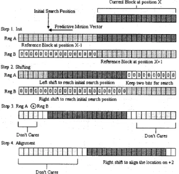
Fig. 1. Illustration of ABME search strategy withXORblock-matching criterion. which is derived from simple filtering and decimation opera-tions. The feature-extraction filters adopt linear and symmetric characteristics, which are amenable for software processing and hardware pipelining. For real-time acceleration, we design the software and hardware pipelining architectures to implement ABME for bandwidth reduction.
This paper is organized as follows. In Section II, we describe the proposed fast motion estimation. We focus on pipelined ar-chitectures including software implementation and hardware re-alization to improve the speed of ABME in Section III. We also provide the complexity and bus bandwidth analyzes of the pro-posed architectures. Section IV shows the experimental results using MPEG-4 video reference software, and we conclude in Section V.
II. ABME
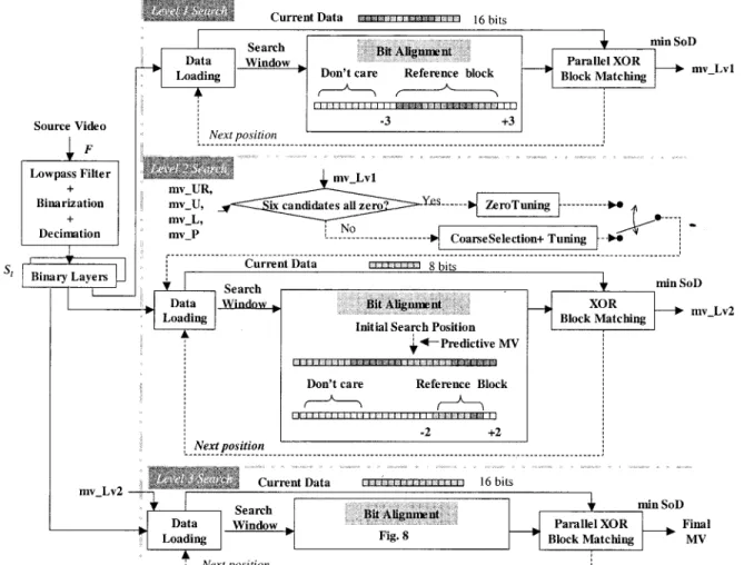
In this paper, we propose an ABME algorithm as shown in Fig. 1. It features low computational complexity, reduced data bandwidth, simple software optimization and pipelined hard-ware architectures. The ABME is described with a flowchart, as shown in Fig. 1, and is implemented with the following steps.
Step 1) Construct the binary pyramid structure.
Step 2) Perform the FSXORBoolean block matching with a 3 pixel refinement window at the first level. Step 3) Select the best of the six motion-vector candidates
from the current and previous frames and perform
theXORBoolean block matching within neighboring locations for refinement at the second level. Step 4) Perform the FSXORBoolean block matching with a
2 pixel refinement window at the last level. In Step 1, we perform the following three substeps including filtering, binarization and decimation to build a conventional pyramid structure with binary levels. Each original pixel is compared to a threshold, which is computed from an average of the neighboring luminance pixels, to derive the binary representation. At the decimation stage, the filtered image is then subsampled by two in each dimension of the image to achieve the next layer iteratively. Thus, ABME provides all-binary edge information without an integer layer, as is used in FBPME [16]. In this paper, we adopt a three-layer pyramid structure to balance the computational complexity and the motion vectors precision.
In Step 2, the FSXORBoolean block matching with a 3 pixel refinement window is performed to locate one initial motion vector candidate with a block size of 4 4. The initial motion vector candidate is projected to the next binary level with a block size of 8 8.
In Step 3, based on the spatio-temporal dependencies that exist among blocks, ABME selects the best 8 8 motion vector from six candidates in the current and previous frames using theXORmatching criterion. The candidate with the minimum distortion is used as the starting point for further refinement, with a small window at the second level. Similarly, the resultant
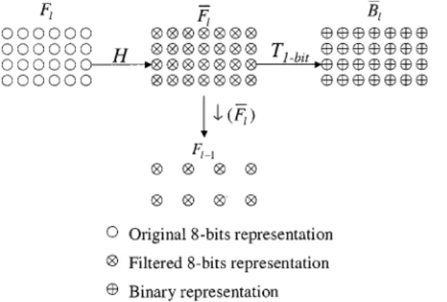
Fig. 2. Combination of binarization and subsampling.
motion vector candidate will be passed onto the next binary level.
In Step 4, a 2 search window refined search is used to derive the final motion vector for a block size of 16 16.
A. Construction of Binary Pyramids
The precise edge information is extracted based on the spatial variations within a small local area of an image. The spatial variations can be extracted with various filters. Assume that an 8-bit representation of the current frame is low-pass filtered to create a new frame . The construction of each pyramidal level in binary format is illustrated in Fig. 2
(1) (2)
with , where is the total number of pyramidal
levels used. The frame is a blurred version of the original frame with the same size at the th level.
Next, the filtered frame is used to create the binary rep-resentation of the current frame. The construction of the binary representation is based on a threshold . The major issue is how to define the threshold to precisely represent the edge in-formation in binary format. The edge inin-formation can be found by differencing the original image and its low-pass version. To compute the binary representation, ABME adopts a novel differ-encing operation using a specified threshold as computed from frame , which provides the average spatial variations for the neighboring area. Thus, the binary representation of the th level is computed by the following 1-bit transformation:
if
otherwise. (3)
Finally, the low-pass frame , which contains most of the spatial information from the original image at the current level, is used to create the input frame in the next pyramidal level. To compute the next level, the frame is by decimating every other pixel to yield the new frame , as described in the following equation:
(4)
Fig. 3. Six motion vector candidates for Level 2 search of ABME.
(a) (b)
Fig. 4. Illustrations of the check points for fine-tuning at Level 2. (a) Tuning module. (b) Zerotuning module.
To achieve a tradeoff between the motion vector precision and the computational complexity, we select a three-level pyramid for motion estimation. The levels are denoted as Level 1, Level 2, and Level 3 (original picture size), respec-tively. Using a simple decimation, the pyramidal levels has three block sizes of 4 4, 8 8, and 16 16.
B. Block Matching
In ABME, the matching criterion is a bit-wise sum of differ-ence (SoD)
(5)
where denotes the current binary block at the th
level and denotes the reference binary
block with offset ( ) from the left top corner of the current block. Since the frame data are in all-binary formats, a simple XORoperation is used to compute the difference.
Consequently, the advantages of the proposed ME approach can be analyzed as follows. At Level 1, we perform FS with a search range of 3 instead of a search range of
, where is the target search range. Thus, with a smaller window we can get a motion vector covering 16 times the actual search area. At Level 2, the search algorithm contains two steps, including the coarse search and fine-tune search. As shown in Fig. 3, the six motion vector candidates, which come from the upper right (UR), upper (U), left (L), Level 1 (Lv1), temporally previous (P) blocks, and the center (C), are consid-ered for the Level 2 search. The center candidate denotes the zero motion vector. When all six candidates are equal to zero, we use the zero motion vector as the final candidate and further check its eight surrounding check points as shown in Fig. 4(b). If the six motion vector candidates are different from each other, the coarse search stage in Fig. 1 is used to choose the best mo-tion vector based on the minimal SoDs. The best candidate is passed onto the fine-tune search, where the four neighboring
TABLE I
LOW-PASSFILTERSADOPTED INTHISPAPER
positions as illustrated in Fig. 4(a) are checked. The best mo-tion vector, derived from the fine-tune stage, is the output of Level 2, and which is passed onto Level 3 for further refinement within a search range of 2. To further reduce the computational complexity, an optional counter is used to register the repeat oc-currence of motion vector for each macroblock. If the motion vectors remain identical for the past four frames, we assume the current macroblock is static and skip the motion search and only do a refinement within a smaller search range of 1. With all-binary representation,XOR operation, and a smaller search window, we can improve the speedup of the motion estimation with only minor loss of the reconstructed image quality.
C. Binarization Efficiency
Since the average spatial variation is used to derive the edge information, the binarization process affects the motion vector accuracy. Thus, the issue is whether the low-pass filter can really register the average spatial characteristics, which are used to compute the threshold for the binarization process in (3). To resolve this issue, we analyze how various filters affect the motion accuracy and the reconstructed picture quality. Table I presents the low-pass filters adopted in this paper. The first set includes three 2-D filters: , , and
(6)
(7)
(8)
The second set consists of three one-dimensional (1-D) sep-arable 13-tap Hamming filters with distinct cutoff frequency at 20%, 25%, and 30% of Nyquist frequency. For a further reduc-tion of the complexity used in (2), every filter of the second set is a linear-phase FIR filter with coefficients in the form of .
For a 1-D filter with taps, i.e., , the
low-pass frame is computed as
(9) where
(10) For instance, a five-tap filter with the coefficients of can be implemented with only SHIFTandADDoperations. The typical cost of such operations on various modern computer architectures is one cycle. Thus, this type of filter can achieve significant speedup over the original filters, although it is not designed with a specific filter design methodology. The filters of the second set are as follows in (11)–(13):
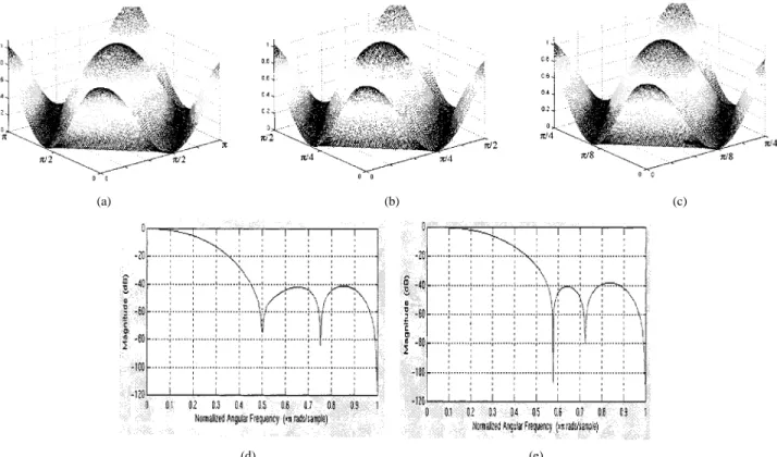
(11) (12) (13) Fig. 5 shows the frequency responses of the filters compared in this paper. Basically, the low-pass filter with a small cutoff fre-quency removes less amount of the average spatial variation and retains more high frequency components in the binary represen-tation of , as shown in (3). As shown in Fig. 6(a)–(c), the frame that is extracted with the filters or retains more high frequency information than the frame that is extracted with the filter . The additional high-frequency information retained may increase the precision of the all-binary edge infor-mation. For practical implementation, there is a need to select a tradeoff between the filter tap number and coding efficiency. Ad-ditionally, the complexity of the binarization processes can be re-duced with the use of linear-phase FIR separable filters, which can be implemented in a pipelined fashion.
III. PIPELINEDARCHITECTURES: CASESTUDY FOR SEVERALHARDWAREPLATFORMS
To demonstrate that ABME is desirable for pipelined archi-tectures, we investigate specific implementations to achieve
(a) (b) (c)
(d) (e)
Fig. 5. (a)–(c) Frequency responses of Type 1, nonseparable 2-D filters. (d)–(e) Frequency responses of Type 2, 1-D separable, and 13-tap Hamming filters with sampling frequencies of 20% and 25%.
Fig. 6. All-binary edge information at Level 3 of the pyramidal structure derived by the various filters and binarization process.
pipelined processing for various architectures, which include general-purpose architectures such as x86, single instruction multiple data (SIMD) architectures using Intel’s MMX tech-nology [19] and systolic arrays [20]. In all implementations, we use the filter in (6) for simplicity. To verify the ef-fectiveness of our approach over the FS approach, we use the x86 system and C language for simulations. Finally, we will compare the computational complexity and bus bandwidths of ABME to those of the FS approach. Since the initial locations and the storage units of each level are distinct, the speedup of the block matching is accomplished level by level with our proposed method. The level-by-level implementation allows
low memory bandwidth consumption with frequent data access for block matching.
A. Generic Functional Partitions and Software Implementation
Our pipelined architecture contains three major common modules including the integrated construction, compact storage and parallel block matching. For each module, the size and type of the storage are constrained by the data bins/registers defined in the individual architecture, which provides various distinct sizes of data storage devices/registers. To implement each generic module in an x86 system, the use of C language provides three basic data bins including INT (32 bits), SINT
Fig. 7. Parallel processing of the binarization process. PixelF (x; y) indicates the pixel at the coordinates (x; y) within the processing frame of the lth pyramid level. The shadowed circle represents the current pixel to be binarized.
(16 bits), and UCHAR (8 bits). In the Intel SIMD architecture using MMX technology, for every module, the largest data bin is a 64-bit MMX register. Unless larger data bin is available, the optimization processes for this kind of architecture are similar to that of x86 architectures. For further reductions in memory bandwidth between the processing units and reductions in operation counts on both architectures, the use of the largest data bin is preferable to store the binary representation of several consecutive blocks in a packed way [21].
1) Integrated Construction: The first module, integrated
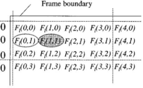
construction of the binary pyramid, consists of three processes including filtering, binarization and subsampling processes. This module can be enhanced in two submodules including the boundary partitioning and parallel processing. The basic idea of the boundary partitioning is to skip the branching decision on whether the current data is located at the frame boundaries. The first submodule, boundary partitioning, is achieved by classifying the frame into the nine regions: four corners, two boundary rows, two boundary columns, and the interior. The second submodule, parallel processing, is achieved by loading multiple sets of pixels that are sequentially stored in registers with larger size. In Fig. 7, we demonstrate an example of using the filter to construct the low-pass frame in (2). Interestingly, the derivation of the low-pass frame using the filter is equivalent to the computation of the average value of the neighboring pixels surrounding the check point with a distance of one.
Assume the frame data are stored in the data bin, named SINT, under C/C++ environment in x86 system. Fig. 7 demonstrates
an example of processing the pair .
We first load four neighboring pairs, represented as
, , ,
and , from the reference frame into four
32-bit INT registers, which are denoted as , ,
, and . After loading, the summation and rounding operations can be performed directly, since no overflow or underflow occurs for the frame data because only 8-bit wide data are stored in a 16-bit data bin. After summation and rounding, the results are put back to a 32-bit INT register
(14)
where the value is used for the rounding purpose of the concurrently processed pixels.
We can derive the threshold for each pixel by extracting the pair of the values inside the register
(15) where refers to the logicalSHIFT RIGHToperation. The de-rived threshold is used for binarization in (3). With this opti-mization, the construction stage has about a 30% improvement in speed.
If a larger bin is available, the speedup can be increased by a factor that equals to the number of the pixels that can be si-multaneously loaded into a single bin. In the Intel SIMD archi-tecture using MMX technology, the binary pyramid can be sim-ilarly constructed with the boundary partitioning and parallel processing as described previously for x86 architectures. How-ever, the parallelism achievable based on MMX technology is almost doubled due to the 64-bit architecture. Based on (14) and (15), the improvement in speed is 63%.
2) Compact Data Storage: The binary representation of
frame data results in desirable compact storage for the pyramid layers. At Level 1, each row of a 4 4 block occupies only 4 bits. Hence, one data bin with 4 bits can store the same row for several sequential blocks. At Level 2, the six candidates may be located at several distinct and discontinuous spaces in the memory. The packing of multiple blocks into a single bin, like the blocks of Level 1, is ineffective to improve the efficiency. Thus, for both computer architectures, we store each block of Level 2 with separate data bins. Each block needs eight 8-bit data bins. Using the same concept of Level 1, we pack every row of the successive 16 16 blocks at Level 3 into a single data bin of size 16 . Note that the widest data bin in both architectures is only used for speedup of block matching.
3) Parallel Block Matching: The block diagrams for our fast
block matching using all-binary edge information are illustrated in Fig. 1, and include loading, bit alignment, and (parallel)XOR block matching. The loading module puts each group of sequen-tial data into the corresponding bins of larger size for reducing memory access. Since the frame data in binary format has been compactly and sequentially stored, the memory access becomes a simple fetch instruction. Thus, the loading module loads the current data and the reference data in the search window into the on-chip memory. As shown in Fig. 1, for each group of four sequential 4 4 blocks at Level 1, we load the same row of the current four blocks into a specified SINT register one by one, and put the corresponding row of the reference blocks into an INT register one by one in x86 architecture. Thus, the four SINT registers can be used for following parallel block matching, and the speedup is increased by about four times in comparison to the block-by-block matching scheme. The same processes are employed in the Intel SIMD architecture, except for the use of 64-bit data bins to handle each group of eight sequential 4 4 blocks at Level 1. Thus, the four MMX registers can be used for a factor of 8 in parallelism as compared to the block-by-block matching method.
The bit alignment module synchronizes the reference data in the search window with the current data. After bit alignment, (parallel)XOR block matching, Table Lookup, and SoD com-parison submodules are adopted for finding the motion vector with the minimal SoD. TheXORoperation is applied to compute the distortion. To derive the block SoD after theXORmodule, we use a table lookup operation in the Table Lookup submodule, by counting the number of “1’s” in this temporary register. Finally, comparing all SoDs, we can determine which motion vector is the best for each of the four blocks separately in the SoD Com-parison submodule. While going through all blocks of the cur-rent frame, the resultant motion vector with the minimal SoD is selected.
The optimization processes of motion vector search in ei-ther architecture are similar, except that the 64-bit registers can handle more successive blocks simultaneously and special in-structions are used to operate on the registers in SIMD architec-ture. Thus, only relevant steps in the x86 system are described in detail to show how to achieve such parallelism. The optimiza-tion of the (parallel) XOR block-matching modules will be ex-plained in detail in Level 1. For the remaining levels, the relevant descriptions are skipped.
• Level 1: Since each block of Level 1 has the initial lo-cation assigned sequentially, we can simultaneously com-pute SoDs for four blocks in x86 architecture and de-rive SoDs for eight blocks with MMX technology in a row-by-row manner.
Step 1) Loading: Since we process four neighboring blocks of size 4 4 for the current frame simul-taneously, 16-bit data is needed to compute the SoDs for each row. With the search range of 3, the data of the reference frame that needs to be loaded into a data bin should be larger than or equal to 22 bits for parallel block matching. Step 2) Bit Alignment: For the initially loaded data, we
align the reference block with a horizontal offset of 3 relative to the current blocks at Level 1, as shown in Fig. 1. To move to the next check point, the overlapped area bits are reused by right shifting the bits in the register by one.
Step 3) XOR: The row-wise matching is illustrated in Fig. 1, where each square indicates a single bit. Since the SINT contains 16 bits, only the lower 16 bits of the reference register will be compared with the current data usingXOR. ThisXORresult is temporarily stored in another SINT register and three 4-bitSHIFTand threeAND(as a mask) op-erations are required to get the SoDs for the four blocks, respectively.
Step 4) Table Lookup: Diff is a SINT register that stores the corresponding SoD of the current row of the
th block as computed by
(16)
Fig. 8. Bit alignment to the initial search position for the Level 3 search. The overall SoD for each block equals the sum of the SoDs for each row.
Step 5) SoD Comparison: Comparing all SoDs, we can determine which motion vector is the best for each of the four blocks, respectively.
• Level 2: For both architectures, we store each block in separate data bins without packing. For each distinct motion vector candidate and each predefined check point, the Level 2 ME computes the block difference in a row-by-row manner. For the current row, we need not only load the required bits within the predefined search range into the registers, but also align the reference data by shifting the registers bits, which is equal to the horizontal offset indicated by the current motion vector. For the consecutive check points in Fig. 4, extraSHIFT operations are necessary to align the reference data. The bit alignment process for the Level 2 search is shown in Fig. 1.
• Level 3: The modules including loading and bit alignment for Level 3 blocks in x86 architecture are optimized as fol-lows. In the loading module, one 32-bit register A stores the same row of the reference data at the block and the previous block ( ). The other 32-bit register B stores the same row at block ( ). Both registers contain partial bits of reference data within the specified search window, as demonstrated in Fig. 8. To align the reference data, the horizontal predictive motion vector is initially set to be 10 as an example. Register A is shifted left by 10, while register B is shifted right by 6 to reach the initial search position. We combine the contents of the two reg-isters with a simpleXORoperation. In the last step, the ref-erence bits are aligned to match the initial search location 2. When we move to the next location in the same row, an extraSHIFToperation is needed to synchronize the pair of data for matching.
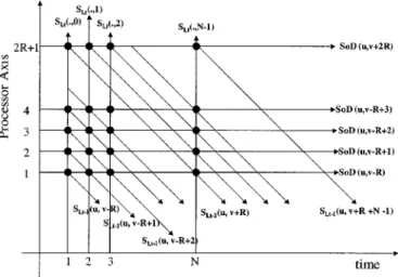
Fig. 9. Spatio-temporal representation of parallel block matching for each column of check points using systolic arrays, where each bold dot denotes a processor element. TheS (:; :) indicates the lth level binary representation of the current frame at timet. The S (:; :) present the reference data at the same pyramid level of the temporally previous frame. For block matching, the block dimension is set asN 2 N and the search range is 6R. The motion vector from the current block to the corresponding reference block is indicated by (u; v).
B. Systolic Arrays
The all-binary representation for each pyramid level reduced the storage from bytes to bits, which can be stored as groups of row or column vectors. Since the vectors are consec-utively stored, we should be able to access the information effi-ciently through pipelining the binary information and overlap-ping the processing time for each matching process. Since the current block is fixed in the search process, the reference data can be accessed and propagated in the form of pipelines for an ASIC implementation. In short, it is advantageous to employ systolic arrays [20] to design the hardware implementation for ABME.
In Fig. 1, theXORblock-matching module is optimized with systolic arrays for Level 1 and 3 searches. The realization based on systolic arrays for each column of check points is shown in Fig. 9, where the spatio-temporal representation of theXOR block matching is defined in (5). The binary data of both the current block and the reference block can be transported into the processors in an order such that the resultant SoDs can be computed by summing theXOR block-matching criterion in a row-by-row manner. For each block of the current or reference frame, the binary data of each row is stored as a 1-D vector. Each pair of vectors from the current and reference blocks is delivered to the processing element (PE) for computing the SoD, but the current block is further passed to the next PE through the systolic arrays. Consequently, for each column of check points, we will obtain ( ) final SoDs, as shown in Fig. 9.
To cover all check points of size , we compute and compare the SoDs with a pipelined approach, where each PE will handle a specified row of the reference blocks at the same column within the search window. Based on the pipelined ap-proach, we can process each column within the search window sequentially in time. That is, we check every check point lo-cated at the first column of the search window and select from these check points the best candidate with the minimal SoD.
The pipeline scans through the subsequent 2 columns using all PEs in the array, and we obtain the final candidate with the minimal SoD among all search points, which leads to the resul-tant motion vector for the current block. The pipelined
architec-ture requires ( ) PEs, cycles, and
memory access to get the reference data
and memory access to load the current data from
the on-chip memory to compute SoDs of each block
with bits, where additional 2 cycles are used for pipeline initialization and each memory access takes bits of the ref-erence block and bits of the current block. The gate counts for constructing ( ) PEs are small, while memory access efficiency poses the challenge.
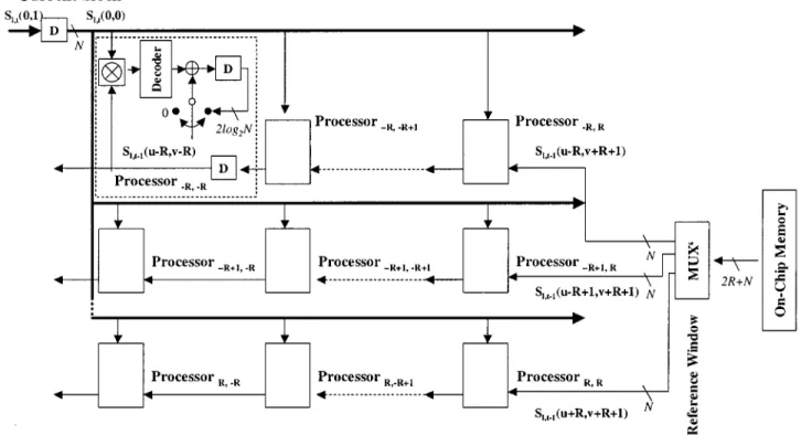
To further reduce the latency for the memory access, we pro-pose a 2-D parallel block-matching architecture using systolic arrays. The 2-D architecture removes the overhead of loading the overlapping bits within the successive reference blocks by simultaneously fetching all the bits within the ref-erence window into the on-chip memory. From each row of ( ) bits, we then de-multiplex each group of serial bits into the corresponding pipeline. The overall SoD for each pair of block is computed in a PE, which is implemented with detail circuits as shown in Fig. 10. The proposed PE performsXOR op-erations of multiple bits in parallel, computes the number of 1’s using a decoder and, finally, accumulates the total number of 1’s as the SoD. The relationship between the PEs, the current block, and the reference block can be represented as the block diagram in Fig. 10. The dimension of the input blocks to each PE is re-lated to the block dimensions of the current pyramid level. For example, the block dimension is 4 for Level 1 and is increased to 16 for Level 3. With the 2-D parallel architecture, we require
PEs, ( ) cycles, and ( ) memory access
to get the reference data and memory access to load the cur-rent data from the on-chip memory to derive SoD for a search range of value and each block with bits. Each memory ac-cess fetches ( ) bits of the reference block and bits of the current block from the on-chip memory. As compared to the 1-D pipelining architecture, the speedup is ( ) times the computation of SoDs, and each reference data is fetched from the on-chip memory just once, which is the minimal memory access to load the bits into the system. Since ABME requires a small search range for each level, the increase of gate count in realizing the 2-D pipelining architecture is still within a reason-able range. Although we provide an implementation example, it is possible to be more efficient in mapping ABME onto a phys-ical hardware like ASIC or FPGA chips.
C. Complexity Analysis and Bus Bandwidth
In this section, we provide the analysis of computational complexity of ABME on x86 architectures with and without the alternative implementation of parallelXORblock-matching module in Fig. 1 using the 2-D systolic arrays. The analysis is based on how a single block computes its motion vector and the memory access per second for a particular frame rate. The notations of , , , and (fps) denote the frame width, frame height, search range and frames per second, respectively. The block size is assumed to be 16 16, which is the most commonly used in video compression standards.
Fig. 10. Detailed implementation of parallel 2-D block matching. A “Decoder” is used to compute the number of 1’s within each input data and “D” is the delay element. The SoD stored in the delay element of the inner loop is accumulated with all outputs from the Decoder. The overall SoD of concurrently matched blocks is compared by a comparator, which is not shown here. The motion vector with minimal SoD will be found after going through all of locations within the search areas. TheS (:; :) indicates the lth level binary representation of the current frame at time t. The S (:; :) presents the reference data within the same pyramid level of the temporally previous framet 0 1. For block matching, the search range is 6R. The motion vector from the current block to the corresponding reference block is indicated by (u; v). Delay element “D” next to the decoder stores the accumulated SoD for the corresponding position within the search area.
1) Computational Complexity Analysis: For each block, the
traditional FS using sum of absolute difference (SAD) needs to process all 4 search points within search window. Each loca-tion takes operations, where the three operations consist of one subtraction, one absolute value and one addition opera-tion for each pair of data. Hence, the computaopera-tional complexity of FS to obtain a single motion vector is approximated as
(17) operations per macroblock. Based on the theoretical best-case scenario for FS using the 32-bit register in the x86 system, ob-taining a single motion vector is approximated as
(18) operations per macroblock. For the same search area, the total operations required for the proposed architecture without the use of 2-D systolic arrays, labeled as , to compute a motion vector are
(19)
per macroblock, where , , , and represent the
operation counts for the pyramid construction and the motion search at each level of the binary pyramid, respectively. The details of derivation for these four counts in (19) are described in Appendix A.
The use of the 2-D systolic arrays for Parallel XOR block-matching modules at Levels 1 and 3, denoted as , reduces the total operations per macroblock to
(20)
Comparing the values of , , and
, we find that our algorithm outperforms the FS, which is consistent with the computational complexities shown in Table II for various search ranges.
2) Memory Bandwidth Analysis: In this section, we analyze
total memory bandwidth for loading the data from the current and reference frames. For the FS, the total bandwidth consump-tion in bytes per second is
(21)
where the and is the memory bandwidth to
ac-cess the data for the current and reference frames. Assume that the current block is loaded simultaneously into on-chip memory with 16 16 UCHAR bins. Thus, to access the data for the
cur-rent frame of size requires
(22) bytes.
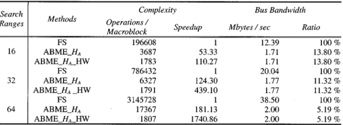
TABLE II
COMPUTATIONALCOMPLEXITIES ANDBUSBANDWIDTHS OFFSANDABME WITH ANDWITHOUTHARDWAREACCELERATION. FRAMESIZE ISW 2 H = 352 2 288AND THEFRAMERATEF IS30FPS
Assume that the reference block is loaded simultaneously
into on-chip memory with UCHAR bins. When we
move to the next block, the data for overlapped area are reused
and the bandwidth required is . Thus, to
com-pletely load the data from the reference frame needs additional
(23) bytes. The first term denotes the first search window, which takes more operations due to the memory stall in the initializa-tion stage of pipelining. Since the rest of the search windows are overlapped with the previous one, fewer operations are needed. For ABME, the total memory bandwidth consumptions in bytes used in x86 system and in SIMD architecture are, respec-tively
(24) (25) The indicates the bandwidth consumption for loading
the current frame. The remaining terms , , ,
and denote the bandwidth required for accessing the reference frame. The memory bandwidth is derived with specific conditions and the detailed derivation is described in Appendix B.
Our approach can significantly reduce the bus bandwidth as compared to the FS. As the search range is increased, the memory bandwidth for the FS is increased dramatically, as shown in (23), and those for the ABME are increased slightly only due to the increased and . As opposed to the high sensitivity with various to the memory bandwidth for the FS, we find that ABME is insensitive to the search range variation, since the frame size at Level 1 is the smallest and the data from the consecutive blocks can be stored in a larger bin. Such superior performances are consistent with the observations, as shown in Table II.
IV. EXPERIMENTALRESULTS
To show the performances of the proposed algorithm over the FS, we use MPEG-4 reference video encoder and employ a
mac-roblock with size 16 16 for block matching. The performance is analyzed based on the following factors: the video sequences, the encoding conditions, various decimation filters, the ME ap-proaches, and the visual quality of the reconstructed video.
The video sequences with CIF format including Coastguard, Foreman, and Akiyo, and the sequences with QCIF format covering Container and Mother–Daughter are used for testing. The six sequences characterize a variety of spatial and motion activities. We further test two CCIR601 sequences, including Table Tennis and Stefan, which consist of fast moving objects. The fast moving objects within a picture of larger size are adopted to examine the performance and the computational load of ABME approaches. Each source sequence consists of 300 frames.
As for the encoding conditions, each sequence is encoded under the conditions recommended by MPEG committee [17]. The target frame rate is set as 10 fps and the bit rates range from 10 kbps to 2 Mbps for various sequences. For finding the precise motion vector, the search range is 16 for each sequence and the range is increased to 32 for the CCIR-601 sequences.
As for the decimation filters, the 2-D filters and 1-D sepa-rable filters as summarized in Table I are used to understand the impact of the individual filter on the binarization and coding ef-ficiency of ABME.
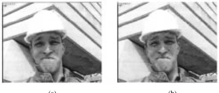
ABME and FS are used for comparison based on the coding efficiency and the visual quality of the reconstructed video in PSNR values.
Based on the experimental results in Tables II and III and Fig. 11, we found the following.
1) As compared to the FS, the proposed approach has sig-nificantly reduced the computational complexity and the memory bandwidth. The loss of the reconstructed video quality for slow moving sequences like Mother–Daughter and Akiyo is negligible, while for high motion sequences such as Foreman and Stefan, the loss is moderate. The experiments using the high motion sequences and large picture sizes show that the proposed approach has out-standing coding efficiency with a gradually increased cost for computation.
2) As the number of taps of the low-pass filter is increased, the accuracy of binary motion search is increased. This is because the long tap of the low-pass filter can capture
TABLE III
PERFORMANCECOMPARISON OFABME VERSUSFS BASED ON THEVARIOUSENCODINGCONDITIONS, FILTERS,ANDVISUALQUALITY INPSNR
(a) (b)
Fig. 11. Comparison of the reconstructed frame from the (a) FS and (b) ABME approaches.
more precise average spatial variation so that the 1-bit information left in the pyramid is more meaningful for
block matching. Furthermore, for the 1-D separable fil-ters, smaller cutoff frequency will increase the binariza-tion efficiency by leaving more detailed informabinariza-tion into the pyramid levels. Finally, the large taps will increase the computational complexity. Thus, there is a tradeoff between the motion accuracy and the computational cost.
V. CONCLUSIONS
According to the experimental results, the proposed ABME shows satisfactory visual quality. It not only takes the benefits of low computational complexity and low memory bandwidth consumption, but also insensitivity to search range increase. We
also demonstrate that with better binarization methods, the vi-sual quality can be further improved. With this feature, our al-gorithm can provide flexible configurations. System designers can choose the binarization methods depending on the available memory, computational power, display resolution, or data bus bandwidth provided by their system. For example, the character-istics of wireless mobile phones have less computational power, lower display resolution, and less available memory. Thus, the smallest filters should be used for the best execution speed, while its visual quality is still acceptable for the low-resolu-tion display. On the other hand, for a faster machine such as today’s personal computers or high-end DSP systems, a filter with better frequency response can be applied, since its compu-tational power can afford more complexity. In addition, various optimization methods can be developed for specific platforms with different register sizes. Thus, ABME is more flexible than other motion estimation algorithms.
We also demonstrated platform-specific optimizations for several hardware architectures, including x86, SIMD using MMX, and systolic arrays. From the operation counts, we showed that ABME is very desirable for software imple-mentation on a general-purpose processor system. We also show that ABME can be realized with a parallel-pipelined implementation for ASIC design and allows tradeoffs between Silicon area, power consumption and visual quality during the hardware design phase. Thus, we conclude that ABME is versatile and effective for multimedia systems in both software and hardware platforms.
APPENDIX
A. Complexity Analysis
With a search window of size 4 andXORoperations for matching a macroblock of size 16 16, the proposed fast mo-tion estimamo-tion approach needs operations in total as shown in (19). The search range of Level 1 is reduced to and the block sizes from Levels 1 to 3 are 4 , 8 , and 16 , respec-tively. To construct the binary pyramid as defined by (14) and (15), the binarization process requires 4.5 operations per pixel on the average. Thus, to build the binary pyramid requires
(26) operations per block.
As for the block-matching process, because the data storage techniques are different from level to level, the operations required for each level are analyzed individually. In Level 1, each pack of four blocks stored in the four SINT bins forms a matching unit, which contains the data in the current row where the four blocks are sequentially stored. To complete the derivation of the four SoDs, it takes 15 operations for every row of the block within the search window. The 15 operations include one register shifting for XOR, three AND operations, and three SHIFT operations to extract the four bit-wise SoDs, four table lookup operations, and four addition operations to accumulate the SoDs of the four macroblocks processed
concurrently. Hence, the total operations at Level 1 for each macroblock are
(27) At Level 2, we analyze the worst case, which means the six candidates plus four tuning locations are nonoverlapped. Basi-cally, there are ten locations that need to be checked in this case. Note that eight UCHAR bins store each row of a Level 2 block. To drive the final SoD, it takes four operations for each location, where the four operations including oneSHIFToperation for one XOR, one table lookup and one addition operation to sum the block SoD. Thus, this level costs
(28) operations per block.
The computational analysis of Level 3 is similar to Level 2, but with a larger block size and a fixed search range. The number of search locations is 25 and 16 SINT bins cover all rows of a Level 3 block of size 16 16. Thus, the Level 3 search needs
(29) operations per block.
Thus, the total operations required for finding a motion vector using the proposed algorithm is
B. Bandwidth Analysis
For the proposed algorithm in x86 systems without hardware acceleration using the 2-D systolic arrays, the memory band-width (bytes) to load every block of the current frame is
(30) Based on the reusability of the data already in the registers, the memory bandwidth required for each pyramid level to load reference data within a search window per frame is
(31) (32)
Thus, the total memory bandwidth consumption of the pro-posed algorithm is
When theXORmatching modules at Levels 1 and 3 are im-plemented with the 2-D systolic array architecture, the memory bandwidths required for loading reference data within a search window per frame are
(34) (35) respectively.
ACKNOWLEDGMENT
The authors are deeply indebted to the anonymous reviewers for their insightful comments.
REFERENCES
[1] T. Koga et al., “Motion-compensated interframe coding for video con-ferencing,” in Proc. Nat. Telecommunications Conf., Nov./Dec. 1981, pp. G 5.3.1–G 5.3.5.
[2] J. R. Jain and A. K. Jain, “Displacement measurement and its application in interframe image coding,” IEEE Trans. Commun., vol. COM-29, pp. 1799–1808, Dec. 1981.
[3] R. Srinivasan and K. R. Rao, “Predictive coding based on efficient mo-tion estimamo-tion,” IEEE Trans. Commun., vol. COM-33, pp. 1011–1014, Sept. 1985.
[4] K. Chow and M. L. Liou, “Genetic motion search algorithm for video compression,” IEEE Trans. Circuits Syst. Video Technol., vol. 3, pp. 440–445, Dec. 1993.
[5] C. H. Lin and J. L. Wu, “A lightweight genetic block-matching algorithm for video coding,” IEEE Trans. Circuits Syst. Video Technol., vol. 8, pp. 386–392, Aug. 1998.
[6] J. Y. Tham, S. Ranganath, M. Ranganath, and A. Kassim, “A novel un-restricted center-based diamond search algorithm for block motion esti-mation,” IEEE Trans. Circuits Syst. Video Technol., vol. 8, pp. 369–377, Aug. 1998.
[7] A. M. Tourapis, O. C. Au, M. L. Liou, G. Shen, and I. Ahmad, “Opti-mizing the MPEG-4 encoder- advanced diamond zonal search,” in Proc. 2000 Int. Symp. Circuits and Systems, vol. 3, Geneva, Switzerland, May 2000, pp. 674–677.
[8] S. Zhu and K.-K. Ma, “A new diamond search algorithm for fast block-matching motion estimation,” IEEE Trans. Image Processing, vol. 9, pp. 287–290, Feb. 2000.
[9] J. S. Kim and R. H. Park, “A fast feature-based block matching algorithm using integral projections,” IEEE J. Select. Areas Commun., vol. 10, pp. 968–971, June 1992.
[10] B. Liu and A. Zaccarin, “New fast algorithms for the estimation of block motion vector,” IEEE Trans. Circuits Syst. Video Technol., vol. 3, pp. 148–157, Apr. 1993.
[11] P. J. Burt and E. H. Adelson, “The Palladian pyramid as a compact image code,” IEEE Trans. Commun., vol. COM-31, Apr. 1983.
[12] M. Bierling, “Displacement estimation by hierarchical block matching,” SPIE Vis. Commun. Image Processing, vol. 100, pp. 942–951, 1988. [13] B. Natarajan, V. Bhaskaran, and K. Konstantinides, “Low-complexity
block-based motion estimation via one-bit transforms,” IEEE Trans. Circuits Syst. Video Technol., vol. 7, pp. 702–706, Aug. 1997. [14] P. H. W. Hong and O. C. Au, “Modified one-bit transform for motion
estimation,” IEEE Trans. Circuits Syst. Video Technol., vol. 9, pp. 1020–1024, Oct. 1999.
[15] X. Lee and Y.-Q. Zhang, “A fast hierarchical motion-compensation scheme for video coding using block feature matching,” IEEE Trans. Circuits Syst. Video Technol., vol. 6, pp. 627–635, Dec. 1996. [16] X. Song, T. Chiang, X. Lee, and Y.-Q. Zhang, “New fast binary pyramid
motion estimation for MPEG2 and HDTV encoding,” IEEE Trans. Cir-cuits Syst. Video Technol., vol. 10, pp. 1015–1028, Oct. 2000. [17] Information Technology—Coding of Audio-Visual Objects-Part 2:
Vi-sual ISO/IEC 14 496-2: 2001, ISO/IEC JTC1/SC 29/WG 11 N4350, July 2001.
[18] Recommendation H.263 Video Coding for Low Bit Rate Communication, ITU-T H.263, 1998.
[19] Intel Architecture Software Developer’s Manual, vol. 1–3, Intel Corpo-ration, 1999.
[20] W. Moore, A. Mccabe, and R. Urquhart, Systolic Arrays. New York: Adam Hilger, 1986.
[21] S. Sethuraman and R. Krishnamurthy, “Packed binary representations for fast motion estimation on general-purpose architectures,” in Proc. IS&T/SPIE Visual Communications and Image Processing, vol. 3653, San Jose, CA, Jan. 1999, pp. 430–438.
Jeng-Hung Luo was born in Taipei, Taiwan, R.O.C.,
in 1976. He received the B.S. degree in electronics engineering and the M.S. degree from National Chiao Tung University, Taiwan, R.O.C., in 1999 and 2001, respectively.
Currently, he is with the Department of Video Imaging Development, Sunplus Technology Com-pany, Ltd., Hsinchu, Taiwan, R.O.C.
Chung-Neng Wang was born in PingTung, Taiwan,
R.O.C., in 1972. He received the B.S. degree in com-puter engineering in 1994 from National Chiao Tung University (NCTU), Hsinchu, Taiwan, R.O.C., where he is currently working toward the Ph.D. degree in the Institute of Computer Science and Information Engi-neering.
His research interests are video/image compres-sion, motion estimation, video transcoding, and streaming.
Tihao Chiang (SM’99) was born in Cha-Yi, Taiwan,
R.O.C., in 1965. He received the B.S. degree in electrical engineering from National Taiwan University, Taipei, Taiwan, R.O.C., in 1987, and the M.S. and Ph.D. degrees in electrical engineering from Columbia University, New York, NY, in 1991 and 1995, respectively.
In 1995, he joined David Sarnoff Research Center, Princeton, NJ, as a Member of Technical Staff. Later, he was promoted to Technology Leader and Program Manager. While at Sarnoff, he led a team of researchers and developed an optimized MPEG-2 software encoder. In September 1999, he joined the faculty at National Chiao-Tung University, Taiwan, R.O.C. Since 1992, he has actively participated in ISO’s Moving Picture Experts Group (MPEG) digital video coding standardization process, with particular focus on the scalability/compatibility issue. He is currently the co-editor for Part 7 of the MPEG-4 committee, and has made more than 50 contributions to the MPEG committee over the past ten years. His main re-search interests are compatible/scalable video compression, stereoscopic video coding, and motion estimation. He has nine U.S. patents and 26 European and worldwide patents. He has published over 30 technical journal and conference papers in the field of video and signal processing.
Dr. Chiang was a co-recipient of the 2001 Best Paper Award from the IEEE TRANSACTIONS ONCIRCUITS ANDSYSTEMS FORVIDEOTECHNOLOGY. For his work in the encoder and MPEG-4 areas, he received two Sarnoff Achievement Awards and three Sarnoff Team Awards.