Biomechanical Analysis of a Temporomandibular Joint Condylar Prosthesis During
Various Clenching Tasks
Heng-Li Huang, PhD1, Kuo-Chih Su, PhD 2, Lih-Jyh Fuh, DDS, PhD 1,3
Michael YC Chen, DDS 1,3 , Jay Wu, PhD 4, Ming-Tzu Tsai, PhD 5, Jui-Ting Hsu, PhD 1*
1School of Dentistry, College of Medicine, China Medical University, Taichung 404, Taiwan 2Department of Medical Research, Taichung Veterans General Hospital, Taichung 407, Taiwan
3Department of Dentistry, China Medical University and Hospital, Taichung 404, Taiwan 4Department of Biomedical Imaging and Radiological Science, China Medical University,
Taichung, 404 Taiwan
5Department of Biomedical Engineering, Hungkuang University, Taichung, 433 Taiwan
Corresponding author: Jui-Ting Hsu, Professor
School of Dentistry, College of Medicine, China Medical University 91 Hsueh-Shih Road, Taichung 40402 Taiwan
Tel. 886-4-22053366 ext. 2308 Fax. 886-4-22014043
E-mail address: jthsu@mail.cmu.edu.tw; richard@ms32.url.com.tw
Sources of support in the form of grants:
This research was supported by the National Science Council, Taiwan (grant number: NSC 100-2221-E-039-009).
Abstract
The objective of this study was to evaluate the effect of clenching tasks on the stress and stability of a temporomandibular joint (TMJ) condylar prosthesis, as well as on the stress and strain in the whole mandible and bone surrounding 3 screws. Three-dimensional finite element models of the mandible and a TMJ condylar prosthesis employing 3 screws were established. Six static clenching tasks were simulated in this study: incisal clench (INC), intercuspal position (ICP), right unilateral molar clench (RMOL), left unilateral molar clench (LMOL), right group function (RGF), and left group function (LGF). Based on the simulation of the 6 clenching tasks, none of the inserted screws nor the TMJ condylar prosthesis were broken. In addition, the stability of the TMJ condylar prosthesis was sufficiently high for bone ongrowth. For the whole mandibular bone, the maximum von Mises stress and von Mises strain observed in the cortical bone and cancellous bone were yielded by the ICP and RMOL, respectively. For the bone surrounding the inserted screws, the maximum von Mises stress and von Mises strain in both the cortical bone and cancellous bone was yielded by the LMOL. Clenching tasks had significant effects on the stress distribution of the TMJ condylar prosthesis as well as on the stress and strain distribution of the whole mandible and the bone surrounding the inserted screws.
1. Introduction
Unlike hip, knee, and shoulder joints that are independent, paired, and arranged symmetrically on the two sides of the body, the temporomandibular joint (TMJ) is a bicondylar joint. In other words, mandibular ramus comprises condyles on its two ends that function at the same time (Ingawalé and Goswami, 2009). The TMJ has two primary functions, which are mastication and speech. Literature has shown that on average, the TMJ moves approximately 1500–2000 times per day (Mackowiak, 1989) and that it is one of the most regularly used joints in the body. Many people have experienced TMJ pain, known as temporomandibular disorder (TMD) (Ingawalé and Goswami, 2009), which is caused by various factors including dysfunction syndrome, internal derangement, arthritis, and trauma. A study has indicated that the majority of TMD patients are between 20–40 years of age and that the incidence of TMDs among females is 3–8 times higher than that among males (Ingawalé and Goswami, 2009). Clinically, conservative approaches are generally adopted for treating TMDs, such as physical therapy and nonsurgical treatments. Although most patients experience significant improvement after treatments, several may be required to undergo surgical procedures such as arthroncentesis, arthroscopy, or discectomy (Ingawalé and Goswami, 2009). For severe cases of TMDs, such as bony ankylosis, recurrent fibrous ankylosis, severe degenerative joint disease, severe rheumatoid arthritis, and aseptic necrosis of the condyle, artificial TMJ replacement therapy may be required (Ingawalé and Goswami, 2009; Wolford et al., 2003).
More than half a century has elapsed since the introduction of artificial TMJ replacement therapy (van Loon et al., 1995); however, its success rate remains lower than that of artificial total hip replacement, total knee replacement, and dental implants. This might because TMJ is a bicondylar joint: when pathological changes occur on one side of the TMJ, the function on the other side of the TMJ is affected (Ingawalé and Goswami, 2009; van Loon et al., 1998). Mandibular movements involve complex muscle contraction, which lowers the success rate of artificial TMJ replacement therapy. Three major artificial TMJ brands that are currently available on the market
are (1) Nexus CMF (Salt Lake City, UT, USA), (2) TMJ Concepts (Ventura, CA, USA), and (3) Biomet Microfixation (Jacksonville, FL, USA) . Clinically, pain improvement and incisal opening of patients are evaluation parameters used to determine the success of artificial TMJ replacement therapy. Literature has shown that the success rate of such therapy ranges between 30%–100% (Ingawalé and Goswami, 2009).
Although early laboratory studies that investigated the wearing of artificial TMJ replacements were abundant (van Loon et al., 1999; van Loon et al., 2000b), mechanical analyses of artificial TMJ replacements have only garnered widespread attention in the past 5 years. FEM is an essential method of biomechanical analysis used to assess the exterior design and fixation of orthopedic artificial joint replacements and artificial dental implants. It is also employed to simulate the effect that varying bone strengths and movements have on artificial implants (Hsu et al., 2006; Huang et al., 2011; Moazen et al., 2011; Murakami and Wakabayashi, 2014). In recent years, a number of research teams have used the finite element method to conduct biomechanical analyses on artificial TMJ replacements. For example, Ramos and Mesnard (Mesnard et al., 2011; Mesnard et al., 2014; Ramos et al., 2011; Ramos et al., 2014) studied the appearance of the TMJ condylar prosthesis and the location of bone screws fixation; Saha, Kashi, and Chowdury (Chowdhury et al., 2011; Kashi et al., 2010) examined bone quality, bone screws dimensions, and surgical procedures; and Arabshahi et al. (Arabshahi et al., 2011, 2012a; Arabshahi et al., 2012b) explored the appearance of the TMJ condylar prosthesis. In 2010 and 2011, we extensively analyzed the effect of mandibular bone quality on TMJ condylar prosthesis and the mechanics involving the use of bone screws to fixate a TMJ condylar prosthesis (Hsu et al., 2011; Hsu et al., 2010). However, these studies have merely used a single clenching task in their simulations—in other words, only one loading and boundary condition in the finite element simulation was selected. Therefore, the effect of varying clenching tasks on TMJ condylar prosthesis remains unknown.
provided insights into the influences of exterior design, fixation approach, and mandibular bone quality on TMJ condylar prosthesis (Arabshahi et al., 2011, 2012a; Arabshahi et al., 2012b; Chowdhury et al., 2011; Hsu et al., 2011; Hsu et al., 2010; Kashi et al., 2010; Mesnard et al., 2011; Mesnard et al., 2014; Ramos et al., 2011; Ramos et al., 2014). However, the effects of various clenching tasks remain unclear. Therefore, in this study, we explored the effect of clenching tasks on an artificial TMJ condylar prosthesis and surrounding bones.
2. Materials and Methods
2.1 Modeling of the mandible and the TMJ condylar prosthesis
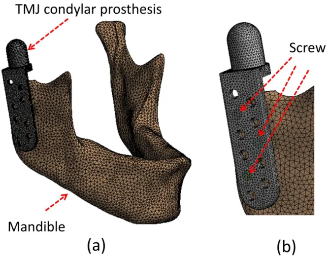
Three-dimensional solid models were created of the human mandible (from computed tomography images) and a TMJ condylar prosthesis (Christensen prosthesis; TMJ, Inc., Golden, CO, USA) (Fig. 1a). The TMJ condylar prosthesis was implanted on the right side of the mandibular ramus and fixed with 3 screws (Fig. 1b). The interface between the prosthesis and the bone was modeled with contact elements that had a coefficient of friction of 0.42 (Hsu et al., 2011). The screw-to-condylar prosthesis and screw-to-bone interfacial conditions were assumed to be bonded. The elastic modulus and Poisson’s ratio of cortical bone, cancellous bone, and Co-Cr-Mo alloy prosthesis were 13.0 GPa and 0.3, 1.6 GPa and 0.3, and 210 GPa and 0.3, respectively (Hsu et al., 2011; Oguz et al., 2009). In total, there were 235,069 nodes (159,696 elements) in the mesh models. The finite element analyses were performed using the ANSYS Workbench finite element package (Swanson Analysis, Canonsburg, PA, USA).
2.2 Muscular force and constraints
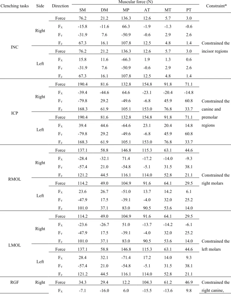
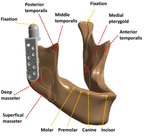
The loading conditions pertained to 6 principal muscles: the superficial masseter (SM), deep masseter (DM), medial pterygoid (MP), anterior temporalis (AT), middle temporalis (MT), and posterior temporalis (PT) (Fig. 2). Six static clenching tasks were simulated in this study: incisal clench (INC), intercuspal position (ICP), right unilateral molar clench (RMOL), left unilateral
molar clench (LMOL), right group function (RGF), and left group function (LGF). The magnitude and directions of the 6 muscular forces and constraint region are listed in Table 1. All raw data for the loading conditions were obtained from a study by Korioth and Hannam (Korioth and Hannam, 1994).
2.3 Convergence test and evaluation parameters
To assess the convergence of the results, a mesh model with 327 703 nodes (224 779 elements) was established and the maximum relative micromotion between bone and the TMJ condylar prosthesis, the maximum von Mises stress of the TMJ condylar prosthesis and screw, and the maximum von Mises strain of the whole bone differed by less than 3%, 2%, and 2%, respectively, which indicated a convergent state.
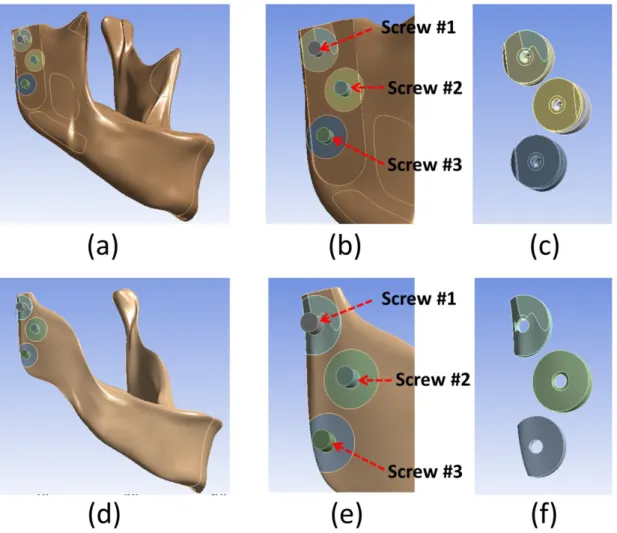
For each of the models analyzed, the following biomechanical parameters were obtained: (1) maximum relative micromotion between the TMJ condylar prosthesis and bone; (2) maximum von Mises stress in TMJ condylar prosthesis and bone screws; (3) maximum von Mises stress and strain in the whole mandible (cortical bone and cancellous bone); (4) maximum von Mises stress and strain in the cortical bone and cancellous bone surrounding the 3 screws (Fig. 3).
3. Results
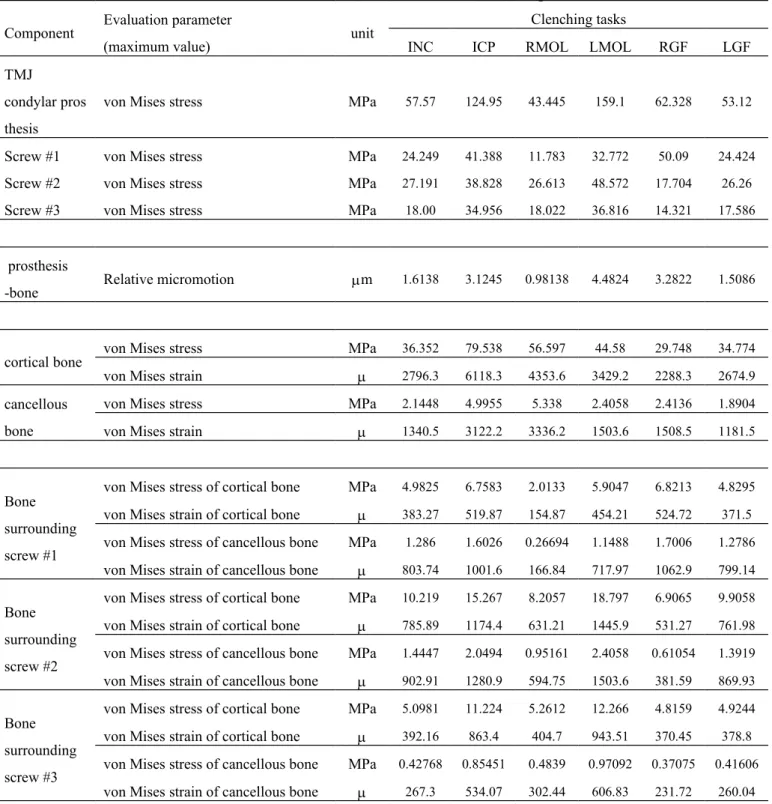
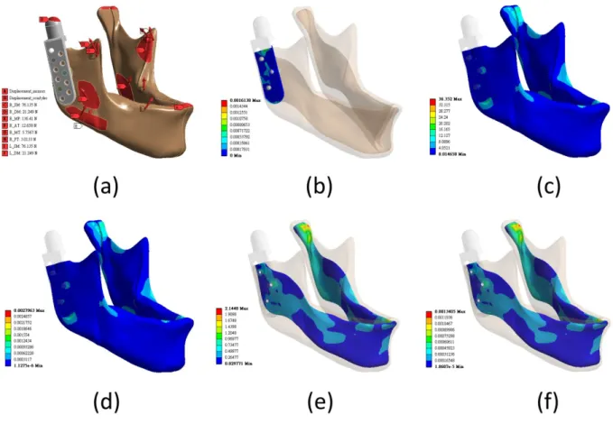
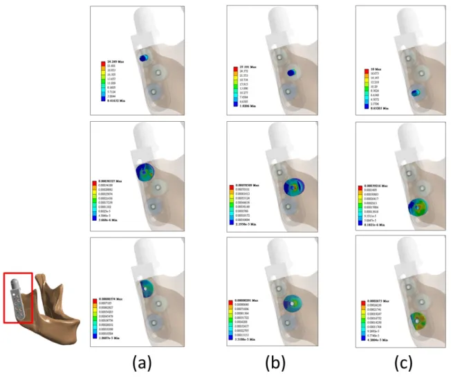
In this study, the following evaluation parameters were used: 6 clenching tasks, the von Mises stress, the von Mises strain, and the relative micromotion between the TMJ condylar prosthesis, 3 bone screws, cortical bone, and cancellous bone. Graphics were used to visualize the INC simulation results, which comprised the relative micromotion between the TMJ condylar prosthesis and bone, and the von Mises stress and von Mises strain of the whole cortical bone and of the whole cancellous bone (Fig. 4). Fig. 5 shows the von Mises stress of the 3 bone screws and the von Mises strain of the cortical and cancellous bones surrounding the bone screws. Table 2 shows the analysis results of the 6 clenching tasks, TMJ condylar prosthesis and bone, 3 bone screws, and von Mises stress and von Mises strain in the bone.
3.1 Relative micromotion between the TMJ condylar prosthesis and bone
The analysis results revealed that the maximum relative micromotion values for the 6 clenching tasks were all less than 5 m and that the maximum and minimum relative micromotion values for the LMOL was 4.4824, which is approximately 4.5 times greater than that for the RMOL value (0.98138 m).
3.2 von Mises stress on the TMJ condylar prosthesis and 3 bone screws
A mechanical analysis of the TMJ condylar prosthesis demonstrated that the values of von Mises stress on the TMJ condylar prosthesis for each of the 6 clenching tasks were all less than 160 MPa and that the maximum LMOL value (159.1 MPa) was approximately 3.6 times greater than the minimum RMOL value (43.445 MPa). Furthermore, the maximum von Mises stress on the 3 bone screws for each of the 6 clenching tasks ranged between 11.783 MPa (RMOL, screw #1) and 50.09 MPa (RGF, screw #1). The von Mises stress on screw #2 in the INC, RMOL, LMOL, and LGF was greater than that on screws #1 and #3. For ICP and RGF, screw #1 yielded a large von Mises stress value. No maximum von Mises stress was observed in screw #3 regardless of the clenching tasks involved.
3.3 von Mises stress and von Mises strain of the whole bone
A whole mandible cortical bone mechanical analysis indicated that the maximum and minimum von Mises stress occurred at the ICP (79.538 MPa) and the RGF (29.748 MPa), and the maximum and minimum von Mises strain also occurred at the ICP (6118.3 ) and the RGF (2288.3 ). However, the mechanical analysis of a whole mandible cancellous bone revealed that the locations in which the von Mises stress and von Mises strain occurred differed from those of the cortical bone. In the cancellous bone, the maximum and minimum von Mises stress occurred at the RMOL (5.338 MPa) and the LGF (1.8904 MPa) and the maximum and minimum von Mises strain occurred at the RMOL (3336.2 ) and the LGF (1181.5 ). Overall, the von Mises stress and strain on the cortical bone were greater than that on the cancellous bone.
3.4 von Mises stress and von Mises strain of bone surrounding the screws
The mechanical analysis of the bone surrounding the bone screws showed the following von Mises strain and stress values regardless of the clenching tasks involved. The cortical bone surrounding the 3 bone screws exhibited a von Mises stress less than 18.797 MPa (LMOL, screw #2) but greater than 2.0133 MPa (RMOL, screw #1), and yielded a von Mises strain less than 1445.9 (LMOL, screw #2) but greater than 154.87 (RMOL, screw #1). Conversely, the cancellous bone demonstrated a von Mises stress less than 2.4058 MPa (LMOL, screw #2) but greater than 0.26694 MPa (RMOL, screw #1) and produced von Mises strain less than 1503.6 (LMOL, screw #2) but greater than 166.84 (RMOL, screw #1).
4. Discussion
Most TMDs can be cured by adopting conservative treatment methods. However, for severe cases, artificial TMJ replacement therapy is necessary. Although more than half a century has elapsed since the introduction of artificial TMJ replacement therapy (van Loon et al., 1995), its success rate still trails that of artificial total hip replacement, artificial total knee replacement, and artificial dental implants. This is primarily because mandibular movements are complex and artificial TMJ-based clinical research is lacking, engendering a poorer understanding of artificial TMJ replacement therapy in comparison with that of total hip replacement, total knee replacement, and artificial dental implants. In recent years, several research teams have used the FEM to conduct biomechanical analyses regarding artificial TMJ replacements. However, the effects of various clenching tasks remain unclear. Therefore, in this study, we explored the effects of 6 clenching tasks on TMJ condylar prosthesis and the mandible; the finite element results showed that the different clenching tasks had varying effects on TMJ condylar prosthesis and the surrounding bones.
van Loon et al. (van Loon et al., 2002) proposed 11 requirements of artificial TMJ replacement, where “limitation of condylar translation during mouth opening,” “unrestricted mandibular movements,” “stable fixation to the bony structures,” and “sufficient mechanical strength” are directly related to mandibular muscles. Because different clenching tasks are performed by different groups of mandibular muscles, understanding the effect of these tasks on artificial TMJ replacement is crucial. Finite element simulations are a common tool used for biomechanical analyses, which can obtain parameters not easily measured in in vitro experiments, such as the internal stress and strain of bones and prostheses. Thus, we used the FEM to analyze the effects of clenching tasks on the biomechanical behaviors of TMJ condylar prosthesis and surrounding bones.
contract to perform upward, downward, forward, backward, leftward, and rightward movements. Korioth and Hannam (Korioth and Hannam, 1994) reported that various clenching tasks are performed by 9 mandibular muscles. In studies regarding the finite element simulation of mandible movements and clenching tasks, scholars have assigned 9 (van Essen et al., 2005), 7 (Tie et al., 2006), 5 (Wong et al., 2012), 4 (Daas et al., 2008; Pileicikiene et al., 2007), and 2 mandibular muscles (Oguz et al., 2009) in their loading condition settings. In this study, we simulated clenching tasks involving 6 mandibular muscles: 2 masseter muscles (SM and DM), 1 medial pterygoid muscle, and 3 temporalis muscles (AT, MT, and PT). These muscles are responsible for mouth-closing movements. In addition, the same mandibular muscles were used by Ichim et al. (Ichim et al., 2007) to investigate the strain distribution as the mandible performed clenching tasks.
Three bone screws were used to fixate the TMJ condylar prosthesis based on our previous published study (Hsu et al., 2011), in which we compared the fixation of TMJ condylar prosthesis using varying numbers of bone screws. The study results showed that 3 staggered bone screws can provide optimal implant stability and bone stress and strain distributions in a TMJ condylar prosthesis (Hsu et al., 2011). This finding supported the study conducted by van Loon et al., who performed animal experiments using sheep and found that a TMJ condylar prosthesis could be firmly fixated using 3 screws (van Loon et al., 2000a). In this study, the maximum relative micromotion values between the TMJ condylar prosthesis and bone for the 6 clenching tasks were all less than 28 m, which is the maximum relative micromotion that can be tolerated for bone ingrowth into the implant surface (Pilliar et al., 1986). Therefore, when artificial TMJ condylar prosthesis is fixated in the mandible, bone ingrowth into the surface of the prosthesis, thereby achieving secondary stability, is possible.
When performing the LMOL, the maximum von Mises stress in the TMJ condylar prosthesis was 163.1 MPa, which is 3.6 times greater than the minimum von Mises stress (RMOL, 43.9 MPa). However, this value was significantly less than the stress on the TMJ condylar prosthesis yielded by
using screws composed of cobalt-chromium-molybdenum alloy. Therefore, the fracture or damage of the TMJ condylar prosthesis was unlikely. Of the 6 clenching tasks, the maximum von Mises stress in the 3 bone screws was 48.572 MPa (LMOL, screw #2), which was significantly lower than that yielded cobalt-chrome alloy screws. In a previous study, Chowdhury et al. (Chowdhury et al., 2011) explored the effects of TMJ condylar prosthesis surgical procedures and varying bone screw dimensions using the FEM. Their simulation results showed that the maximum von Mises stress in the TMJ condylar prosthesis was approximately 125 MPa. Their simulation results differed from those of this study because of differences in the loading and boundary conditions as well as the shapes and materials used in the mandible model. In Chowdhury et al., the lower border of the mandible was completely fixed and a vertical force of 300 N was applied to the top head of the artificial TMJ condylar prosthesis (Chowdhury et al., 2011). These loading and boundary conditions differed from those in our simulations, resulting in differences in the maximum von Mises stress that each clenching exerted on the TMJ condylar prosthesis (between 57.57 and 159.1 MPa).
Concerning the von Mises stress and strain generated by the 6 clenching tasks in the whole mandible, the results were as follows: ICP and RMOL yielded a maximum von Mises strain in the cortical and cancellous bones (6118.3 and 4353.6 , respectively); RGF and LGF yielded a minimum von Mises strain in the cortical and cancellous bones (2288.3 and 1181.5 , respectively). After Frost et al. (Frost, 1994, 2004) proposed using strain as an indicator to assess bone remodeling, various “set points” of strain-dependent thresholds were introduced (Al Nazer et al., 2012; Mellal et al., 2004). Mellal et al. [40] indicated that when the von Mises strain in the bone exceeds 4000 , pathologic overload may occur, leading to bone resorption. In addition, when the von Mises strain is lower than 100 , disuse may also occur, which causes bone resorption. In our finite element simulations, although the maximum von Mises strain for ICP and RMOL exceeded 4000 , high strain occurred near the locations of all fixed constraints. This could be attributed to the mesh found in the region. The von Mises strain values in bone were all less than 4000 . von Mises stress was proposed as an indicator in the assessment of bone remodeling; Sugiura et al.
indicated that when stress in bone exceeds 50 MPa, this leads to bone resorption (Sugiura et al., 2000). In our simulations, the same results were observed, that is, the maximum von Mises stress exceeded 50 MPa only for ICP and RMOL, and the maximum von Mises strain occurred in the same location. Therefore, in our simulation of 6 clenching tasks, the addition of TMJ condylar prosthesis was unlikely to cause bone resorption in the mandible. Ramos et al. compared the effects of TMJ condylar prosthesis using the FEM, where the simulation results of straight-type TMJ condylar prosthesis showed that the von Mises stress on the control line ranged from 5–21 MPa. Using the same definition of “control line” used by Ramos et al., our simulation results yielded a range of approximately 3–18 MPa, which was slightly less than that obtained by Ramos et al.; however, the difference was negligible.
Concerning the bone surrounding the 3 bone screws, the maximum von Mises stress values in the cortical bone were all significantly higher than that in the cancellous bone, regardless of the clenching task involved. However, even the largest von Mises stress (18.797 MPa; for LMOL, screw #2) did not reach the 50 MPa threshold for bone resorption as indicated by Sugiura et al. (Sugiura et al., 2000). The maximum von Mises strain values in the cancellous bone surrounding screw #1 were all higher than those of the cortical bone, where the LGF exhibited the greatest difference (2.15 times higher; 799.14 /371.5 ). By contrast, the maximum von Mises strain values in the cortical bone surrounding screw #3 were all higher than those of the cancellous bone, where the ICP showed a substantial difference (1.62 times higher; 863.4 /534.07 ). These results revealed that the maximum von Mises strain value was closely related to the location where the bone screws were fixed. Kashi et al. (Kashi et al., 2010) adopted the FEM to investigate the effect of 4 bone quality types on TMJ condylar prosthesis, which was fixated with 10 bone screws. The simulation results showed that the maximum von Mises stress and strain in the bone surrounding the first bone screw were 10.5–14.5 MPa and 5500–6700 , respectively. These results were all higher than those observed in our simulations because different loading and boundary conditions and only 3 bone screws were used in this study to fixate the TMJ condylar prosthesis.
As with any simulation approach, our study encountered a few limitations. First, we assumed that the mandible featured a homogeneous and isotropic material property. Although this assumption is made in most finite element simulations (Oguz et al., 2009; Tada et al., 2003), future simulations must employ mandible models that closely resemble the materials of human bone. Second, only the Christensen-brand TMJ condylar prosthesis (Chowdhury et al., 2011; Kashi et al., 2010; Mesnard et al., 2011) and 3 bone screws were employed in the simulations; analyses of other prosthesis brands or with different numbers of bone screws have yet to be performed. Third, we only simulated the biomechanical behavior of the TMJ condylar prosthesis (Arabshahi et al., 2011, 2012a; Arabshahi et al., 2012b; Chowdhury et al., 2011; Kashi et al., 2010; Mesnard et al., 2011; Mesnard et al., 2014; Ramos et al., 2011; Ramos et al., 2014); however, the long-term effects of TMJ condylar prosthesis remain to be identified.
5. Conclusion
In this study, we performed simulations and analyzed the effects of 6 clenching tasks on the biomechanical behaviors of TMJ condylar prosthesis and surrounding bone. Our conclusions are as follows:
(1) No TMJ condylar prosthesis or bone screws fractures were identified.
(2) The clenching tasks significantly influenced the von Mises stress and strain in the cortical and cancellous bone.
(3) For whole mandibular bone, ICP yielded the maximum von Mises stress and strain in the cortical bone, whereas RMOL yielded the maximum von Mises stress and strain in the cancellous bone.
(4) LMOL produced maximum von Mises stress and strain in both the cortical and cancellous bone surrounding the bone screws.
Competing Interests
Acknowledgment
This research was supported by the National Science Council, Taiwan (grant number: NSC 100-2221-E-039-009).
References
Al Nazer R, Lanovaz J, Kawalilak C, Johnston J, Kontulainen S: Direct in vivo strain measurements in human bone—A systematic literature review. J Biomech 45: 27-40, 2012
Arabshahi Z, Kashani J, Kadir MRA, Azari A: Influence of Thickness and Contact Surface Geometry of Condylar Stem of TMJ Implant on Its Stability. Physics Procedia 22: 414-419, 2011 Arabshahi Z, Kashani J, Kadir MRA, Azari A: Influence of the TMJ Implant Geometry on Stress Distribution. Adv Mat Res 488-489: 991-995, 2012a
Arabshahi Z, Kashani J, Koloor SSR, Kadir MRA, Azari A: Design Analysis of TMJ Implant under Physiological Loading Condition. Adv Mat Res 488-489: 996-1000, 2012b
Chowdhury AR, Kashi A, Saha S: A comparison of stress distributions for different surgical procedures, screw dimensions and orientations for a Temporomandibular joint implant. J Biomech 44: 2584-2587, 2011
Daas M, Dubois G, Bonnet AS, Lipinski P, Rignon-Bret C: A complete finite element model of a mandibular implant-retained overdenture with two implants: comparison between rigid and resilient attachment configurations. Med Eng Phys 30: 218-225, 2008
Frost HM: Wolff's Law and bone's structural adaptations to mechanical usage: an overview for clinicians. Angle Orthod 64: 175-188, 1994
Frost HM: A 2003 update of bone physiology and Wolff's Law for clinicians. Angle Orthod 74: 3-15, 2004
Hsu JT, Huang HL, Tsai MT, Fuh LJ, Tu MG: Effect of screw fixation on temporomandibular joint condylar prosthesis. J Oral Maxillofac Surg 69: 1320-1328, 2011
Hsu JT, Huang HL, Tu MG, Fuh LJ: Effect of bone quality on the artificial temporomandibular joint condylar prosthesis. Oral Surg Oral Med Oral Pathol Oral Radiol Endod 109: e1-5, 2010 Hsu JT, Lai KA, Chen Q, Zobitz ME, Huang HL, An KN, Chang CH: The relation between micromotion and screw fixation in acetabular cup. Comput Methods Programs Biomed 84: 34-41, 2006
Huang HL, Chang YY, Lin DJ, Li YF, Chen KT, Hsu JT: Initial stability and bone strain evaluation of the immediately loaded dental implant: an in vitro model study. Clin Oral Implants Res 22: 691-698, 2011
Ichim I, Kieser JA, Swain MV: Functional significance of strain distribution in the human mandible under masticatory load: numerical predictions. Arch Oral Biol 52: 465-473, 2007
Ingawalé S, Goswami T: Temporomandibular joint: disorders, treatments, and biomechanics. Ann Biomed Eng 37: 976-996, 2009
Kashi A, Chowdhury AR, Saha S: Finite element analysis of a TMJ implant. J Dent Res 89: 241-245, 2010
Korioth TW, Hannam AG: Mandibular forces during simulated tooth clenching. J Orofac Pain 8: 1994
Mackowiak P: Relief of Pain from Headaches and TMJ. New York: Manhattan Printing, Solomon Books, Incorporated, 1–49., 1989
Mellal A, Wiskott HW, Botsis J, Scherrer SS, Belser UC: Stimulating effect of implant loading on surrounding bone. Comparison of three numerical models and validation by in vivo data. Clin Oral Implants Res 15: 239-248, 2004
Mesnard M, Ramos A, Ballu A, Morlier J, Cid M, Simoes J: Biomechanical analysis comparing natural and alloplastic temporomandibular joint replacement using a finite element model. J Oral Maxillofac Surg 69: 1008-1017, 2011
Mesnard M, Ramos A, Simoes JA: Influences of implant condyle geometry on bone and screw strains in a temporomandibular implant. J Craniomaxillofac Surg 42: 194-200, 2014
Moazen M, Jones AC, Jin Z, Wilcox RK, Tsiridis E: Periprosthetic fracture fixation of the femur following total hip arthroplasty: a review of biomechanical testing. Clin Biomech 26: 13-22, 2011 Murakami N, Wakabayashi N: Finite element contact analysis as a critical technique in dental biomechanics: A review. J Prosthodont Res 2014
Oguz Y, Uckan S, Ozden AU, Uckan E, Eser A: Stability of locking and conventional 2.0-mm miniplate/screw systems after sagittal split ramus osteotomy: finite element analysis. Oral Surg Oral Med Oral Pathol Oral Radiol Endod 108: 174-177, 2009
Pileicikiene G, Surna A, Barauskas R, Surna R, Basevicius A: Finite element analysis of stresses in the maxillary and mandibular dental arches and TMJ articular discs during clenching into maximum intercuspation, anterior and unilateral posterior occlusion. Stomatologija 9: 121-128, 2007
Pilliar R, Lee J, Maniatopoulos C: Observations on the effect of movement on bone ingrowth into porous-surfaced implants. Clin Orthop Relat Res 208: 108-113, 1986
Ramos A, Completo A, Relvas C, Mesnard M, Simoes JA: Straight, semi-anatomic and anatomic TMJ implants: the influence of condylar geometry and bone fixation screws. J Craniomaxillofac Surg 39: 343-350, 2011
Ramos A, Mesnard M, Relvas C, Completo A, Simoes JA: Theoretical assessment of an intramedullary condylar component versus screw fixation for the condylar component of a hemiarthroplasty alloplastic TMJ replacement system. J Craniomaxillofac Surg 42: 169-174, 2014 Sugiura T, Horiuchi K, Sugimura M, Tsutsumi S: Evaluation of threshold stress for bone resorption around screws based on in vivo strain measurement of miniplate. J Musculoskelet Neuronal Interact 1: 165-170, 2000
Tada S, Stegaroiu R, Kitamura E, Miyakawa O, Kusakari H: Influence of implant design and bone quality on stress/strain distribution in bone around implants: a 3-dimensional finite element analysis. Int J Oral Maxillofac Implants 18: 357-368, 2003
Tie Y, Wang DM, Ji T, Wang CT, Zhang CP: Three-dimensional finite-element analysis investigating the biomechanical effects of human mandibular reconstruction with autogenous bone grafts. J Craniomaxillofac Surg 34: 290-298, 2006
van Essen NL, Anderson IA, Hunter PJ, Carman J, Clarke RD, Pullan AJ: Anatomically based modelling of the human skull and jaw. Cells Tissues Organs 180: 44-53, 2005
van Loon JP, Bont Ld, Spijkervet F, Verkerke G, Liem R: A short‐term study in sheep with the Groningen temporomandibular joint prosthesis. Int J Oral Maxillofac Surg 29: 315-324, 2000a van Loon JP, de Bont GM, Boering G: Evaluation of temporomandibular joint prostheses: review of
the literature from 1946 to 1994 and implications for future prosthesis designs. J Oral Maxillofac Surg 53: 984-996; discussion 996-987, 1995
van Loon JP, de Bont LG, Stegenga B, Spijkervet FK, Verkerke GJ: Groningen temporomandibular joint prosthesis. Development and first clinical application. Int J Oral Maxillofac Surg 31: 44-52, 2002
van Loon JP, Otten E, Falkenstrom CH, de Bont LG, Verkerke GJ: Loading of a unilateral temporomandibular joint prosthesis: a three-dimensional mathematical study. J Dent Res 77: 1939-1947, 1998
van Loon JP, Verkerke GJ, de Bont LG, Liem RS: Wear-testing of a temporomandibular joint prosthesis: UHMWPE and PTFE against a metal ball, in water and in serum. Biomaterials 20: 1471-1478, 1999
van Loon JP, Verkerke GJ, de Vries MP, de Bont LG: Design and wear testing of a temporomandibular joint prosthesis articulation. J Dent Res 79: 715-721, 2000b
Wolford LM, Dingwerth DJ, Talwar RM, Pitta MC: Comparison of 2 temporomandibular joint total joint prosthesis systems. J Oral Maxillofac Surg 61: 685-690; discussion 690, 2003
Wong RC, Tideman H, Merkx MA, Jansen J, Goh SM: The modular endoprosthesis for mandibular body replacement. Part 2: finite element analysis of endoprosthesis reconstruction of the mandible. J Craniomaxillofac Surg 40: e487-497, 2012
TABLE LEGENDS
Table 1. Muscular force and constraints of the 6 clenching tasks. All raw data were obtained from Korioth and Hannam (Korioth and Hannam, 1994).
Table 2. Simulation results for the 6 clenching tasks
FIGURE LEGENDS
Fig. 1. Finite element model of the mandible and TMJ condylar prosthesis: (a) whole model; (b) closed view.
Fig. 2. Muscular force (red arrow) and constraints (yellow arrow) applied in the finite element simulation.
Fig. 3. Solid model: (a) whole cortical bone with 3 inserted screws; (b) closed view of (a); (c) cortical bone surrounding the screws; (d) whole cancellous bone with 3 inserted screws; (e) closed view of (d); (f) cancellous bone surrounding the screws.
Fig. 4 Finite element simulation of the INC model: (a) constraint and INC; (b) relative micromotion between the stem and bone; (c) von Mises stress of the whole cortical bone; (d) von Mises strain of the whole cortical bone; (e) von Mises stress of the whole cancellous bone; (f) von Mises strain of the whole cancellous bone.
Fig. 5. Finite element simulation of the INC model: von Mises stress of a bone screw (up), von Mises strain of the surrounding cortical bone (middle), and von Mises strain of the surrounding cancellous bone (bottom). From left to right: (a) screw #1; (b) screw #2; (c) screw #3. The bottom-left image shows the view orientation and region.
Table 1. Muscular force and constraints of the 6 clenching tasks. All raw data were obtained from Korioth and Hannam (Korioth and Hannam, 1994).
Clenching tasks Side Direction Muscular force (N) Constraint*
SM DM MP AT MT PT INC Right Force 76.2 21.2 136.3 12.6 5.7 3.0 Constrained the incisor regions FX -15.8 -11.6 66.3 -1.9 -1.3 -0.6 FY -31.9 7.6 -50.9 -0.6 2.9 2.6 FZ 67.3 16.1 107.8 12.5 4.8 1.4 Left Force 76.2 21.2 136.3 12.6 5.7 3.0 FX 15.8 11.6 -66.3 1.9 1.3 0.6 FY -31.9 7.6 -50.9 -0.6 2.9 2.6 FZ 67.3 16.1 107.8 12.5 4.8 1.4 ICP Right Force 190.4 81.6 132.8 154.8 91.8 71.1 Constrained the canine and premolar regions FX -39.4 -44.6 64.6 -23.1 -20.4 -14.8 FY -79.8 29.2 -49.6 -6.8 45.9 60.8 FZ 168.3 61.9 105.1 153.0 76.8 33.7 Left Force 190.4 81.6 132.8 154.8 91.8 71.1 FX 39.4 44.6 -64.6 23.1 20.4 14.8 FY -79.8 29.2 -49.6 -6.8 45.9 60.8 FZ 168.3 61.9 105.1 153.0 76.8 33.7 RMOL Right Force 137.1 58.8 146.8 115.3 63.1 44.6 Constrained the right molars FX -28.4 -32.1 71.4 -17.2 -14.0 -9.3 FY -57.4 21.0 -54.8 -5.1 31.5 38.1 FZ 121.2 44.5 116.1 114.0 52.8 21.1 Left Force 114.2 49.0 104.9 91.6 64.1 29.5 FX 23.6 26.7 -51.0 13.7 14.2 6.1 FY -47.9 17.5 -39.1 -4.0 32.0 25.2 FZ 101.0 37.1 83.0 90.5 53.6 14.0 LMOL Right Force 114.2 49.0 104.9 91.6 64.1 29.5 Constrained the left molars FX -23.6 -26.7 51.0 -13.7 -14.2 -6.1 FY -47.9 17.5 -39.1 -4.0 32.0 25.2 FZ 101.0 37.1 83.0 90.5 53.6 14.0 Left Force 137.1 58.8 146.8 115.3 63.1 44.6 FX 28.4 32.1 -71.4 17.2 14.0 9.3 FY -57.4 21.0 -54.8 -5.1 31.5 38.1 FZ 121.2 44.5 116.1 114.0 52.8 21.1
RGF Right Force 34.3 29.4 12.2 104.3 61.2 46.9 Constrained the
right canine,
premolars, and molars FY -14.4 10.5 -4.6 -4.6 30.6 40.1 FZ 30.3 22.3 9.7 103.0 51.2 22.2 Left Force 51.4 21.2 132.8 11.1 5.7 4.5 FX 10.6 11.6 -64.6 1.7 1.3 0.9 FY -21.5 7.6 -49.6 -0.5 2.9 3.9 FZ 45.4 16.1 105.1 10.9 4.8 2.2 LGF Right Force 51.4 21.2 132.8 11.1 5.7 4.5 Constrained the left canine, premolars, and molars FX -10.6 -11.6 64.6 -1.7 -1.3 -0.9 FY -21.5 7.6 -49.6 -0.5 2.9 3.9 FZ 45.4 16.1 105.1 10.9 4.8 2.2 Left Force 34.3 29.4 12.2 104.3 61.2 46.9 FX 7.1 16.0 -6.0 15.5 13.6 9.8 FY -14.4 10.5 -4.6 -4.6 30.6 40.1 FZ 30.3 22.3 9.7 103.0 51.2 22.2
Muscular forces: SM = Superficial masseter; DM = Deep masseter; MP = Medial pterugoid; AT = Anterior temporalis; MT = Middle temporalis; PT = Posterior temporalis
Clenching tasks: INC = incisal clench; ICP = intercuspal position, RMOL = right unilateral molar clench, LMOL = left unilateral molar clench, RGF = right group function, LGF= left group function
Table 2. Simulation results for the 6 clenching tasks
Component Evaluation parameter
(maximum value) unit
Clenching tasks
INC ICP RMOL LMOL RGF LGF
TMJ condylar pros thesis
von Mises stress MPa 57.57 124.95 43.445 159.1 62.328 53.12
Screw #1 von Mises stress MPa 24.249 41.388 11.783 32.772 50.09 24.424
Screw #2 von Mises stress MPa 27.191 38.828 26.613 48.572 17.704 26.26
Screw #3 von Mises stress MPa 18.00 34.956 18.022 36.816 14.321 17.586
prosthesis
-bone Relative micromotion m 1.6138 3.1245 0.98138 4.4824 3.2822 1.5086
cortical bone von Mises stress MPa 36.352 79.538 56.597 44.58 29.748 34.774
von Mises strain 2796.3 6118.3 4353.6 3429.2 2288.3 2674.9
cancellous bone
von Mises stress MPa 2.1448 4.9955 5.338 2.4058 2.4136 1.8904
von Mises strain 1340.5 3122.2 3336.2 1503.6 1508.5 1181.5
Bone surrounding screw #1
von Mises stress of cortical bone MPa 4.9825 6.7583 2.0133 5.9047 6.8213 4.8295 von Mises strain of cortical bone 383.27 519.87 154.87 454.21 524.72 371.5 von Mises stress of cancellous bone MPa 1.286 1.6026 0.26694 1.1488 1.7006 1.2786 von Mises strain of cancellous bone 803.74 1001.6 166.84 717.97 1062.9 799.14 Bone
surrounding screw #2
von Mises stress of cortical bone MPa 10.219 15.267 8.2057 18.797 6.9065 9.9058 von Mises strain of cortical bone 785.89 1174.4 631.21 1445.9 531.27 761.98 von Mises stress of cancellous bone MPa 1.4447 2.0494 0.95161 2.4058 0.61054 1.3919 von Mises strain of cancellous bone 902.91 1280.9 594.75 1503.6 381.59 869.93 Bone
surrounding screw #3
von Mises stress of cortical bone MPa 5.0981 11.224 5.2612 12.266 4.8159 4.9244
von Mises strain of cortical bone 392.16 863.4 404.7 943.51 370.45 378.8
von Mises stress of cancellous bone MPa 0.42768 0.85451 0.4839 0.97092 0.37075 0.41606 von Mises strain of cancellous bone 267.3 534.07 302.44 606.83 231.72 260.04 incisal clench (INC), intercuspal position (ICP), right unilateral molar clench (RMOL), left unilateral molar clench (LMOL), right group function (RGF), left group function (LGF)
Fig. 1. Finite element model of the mandible and TMJ condylar prosthesis: (a) whole model; (b) closed view.
Fig. 2. Muscular force (red arrow) and constraints (yellow arrow) applied in the finite element simulation.
Fig. 3. Solid model: (a) whole cortical bone with 3 inserted screws; (b) closed view of (a); (c) cortical bone surrounding the screws; (d) whole cancellous bone with 3 inserted screws; (e) closed
Fig. 4 Finite element simulation of the INC model: (a) constraint and INC; (b) relative micromotion between the stem and bone; (c) von Mises stress of the whole cortical bone; (d) von Mises strain of the whole cortical bone; (e) von Mises stress of the whole cancellous bone; (f) von Mises strain of
Fig. 5. Finite element simulation of the INC model: von Mises stress of a bone screw (up), von Mises strain of the surrounding cortical bone (middle), and von Mises strain of the surrounding cancellous bone (bottom). From left to right: (a) screw #1; (b) screw #2; (c) screw #3. The
