STEP-based data schema for implementing
product data management system
SHEN-CHOU YEH and CHUN-FONG YOU
Abstract. Currently, the challenge of implementing a product data management system (PDMS) is how to ensure system integration and product data exchange is shared between heterogeneous systems. In this research, an integrated data models and implementation approach for PDMS is proposed that uses the STEP (Standard for the Exchange of Product)
model data standard and schema as proposed by the Object Management Group(OMG). The objective of migrating these data schemas is to propose a standardized product data management(PDM)data schema that fulfils its functionality, including product structure management, configuration management, document management, workflow/process management, effectivity management, and engineering change management. The PDM-related data schema that is defined in the STEP standard, the PDM schema, and the Joint Product Data Management (JPDM) Enablers is identified, discussed, compared and migrated in this paper. To solve the barrier of product data exchange and sharing within and between enterprises, a robust and standardized PDM data schema fulfilling the functionality of PDM can be constructed with the proposed migrated data models. The implementation issues of a STEP-based system via these data schema are also discussed. With the proposed approach and architecture, the integrated data models fulfilling the functionality of PDM for PDMS, as well as the methods of implementing STEP-based PDMS, have been demonstrated.
1. Introduction
A product data management system(PDMS)stores and manages complete information of all its products and related activities to ensure a concurrent engineer-ing environment, which facilitates easier and more efficient product development. Currently, an important issue in enterprise integration is the implementation of information systems that facilitate concurrent engineer-ing(Wu et al. 1992, Reddy et al. 1993, Chaxel et al. 1997, Chen and Hsiao 1997). Together with widespread
computer network applications and standard product data representations, PDMS enables an enterprise to conduct its business activities in a more efficient way (Czerwinski and Sivayoganathan 1994, Gu and Chan 1995).
By referencing the PDM-related data schema that was proposed in the Joint Product Data Management (JPDM)Enablers and the Standard for the Exchange of Product model data(STEP)standard, the product data representation is defined and managed via PDMS. The functionality of PDM is the unit of functionality that defines the migrated data models for PDMS implemen-tation. However, the information lost during a product data exchange following data mapping is evident. Although the scope of STEP is expanding, defining the robust data models for PDMS does not include the entire functionality of PDMS. The Application Inter-pretation Model (AIM) in the STEP standard derives from the Application Reference Model (ARM) of the Application Activity Model(AAM)in a specific applica-tion scope. Currently, applicaapplica-tion protocol to imple-ment an entire PDMS does not exist. Furthermore, the PDM-related data models within STEP are based on the configuration management Unit of Functionality (UoF), which is simply a portion of the PDM functionality. Therefore, the STEP standard fails to provide a complete product representation of PDMS.
This paper proposes to solve the requirement of product data exchange as well as the sharing issue of PDMS. Furthermore, to ensure the conformance between the proposed data schema and STEP standard, a PDM-related information definition is employed. The PDM schema (ProSTEP and PDES, Inc. 1998), ab-stracted from AP203, AP210, AP212, AP214 and AP232 within the STEP standard, is a vital reference data model for exchanging PDMS product definition data. The PDM schema is also a solution for product data exchange in PDMS to/from PDMS, and PDMS to/from an Enterprise Resource Planning (ERP) system. The
International Journal of Computer Integrated Manufacturing
ISSN 0951-192X print/ISSN 1362-3052 online # 2002 Taylor & Francis Ltd http://www.tandf.co.uk/journals
DOI: 10.1080/09511920010029263
Authors: Shen-Chou Yeh and Chun-Fong You, Department of Mechanical
JPDM data schema proposed by Digital Equipment Corporation, Fujitsu Limited, International Business Machines Corporation, Matrix One, Inc., Structural Dynamics Research Corp., and Sherpa Corporation, were submitted to the Object Management Group (OMG). This was a response to a request for proposal (RFP)from Product Data Management Enablers (Das-sault Systemes 1997, Digital Equipment Corporation et
al. 1997, Fujitsu Limited 1997, Metaphase Technology,
Inc. 1997, Sherpa Corporation 1997). Based on the experiences of these companies or organizations, for PDMS application, the JPDM data schema should be robust. The objective of migrating these data schema is to construct a PDMS that is robust and standardized, which implements a PDMS to solve the barrier of product data exchange and sharing among enterprises. Section 2 discusses a review of PDMS functionality (CIMdata Inc. 1997)and the comparison of the PDM-related data schema defined in STEP and JPDM, to show the scope and ability of each data PDM-related schema. To provide robust data models for product data management and exchange, the data schema of PDMS, defined in STEP standard, PDM schema, and JPDM, is identified, discussed, compared and migrated in section 3. The migration of these data models is to enable integration of the overlapped portion, excluding those that are different, and to maintain a robust correlation among them. Furthermore, the implemen-tation of a STEP-based system via these data schema is discussed in section 4. Finally, the conclusion of this work contains a discussion and summary of the migration and implementation of these data schema.
2. Review of PDM functionality and data schema in STEP and JPDM
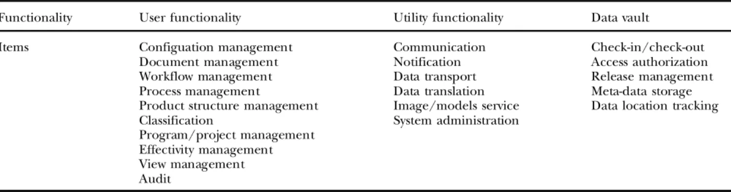
Table 1 presents a robust PDMS composed of an electronic data repository as well as a set of user and
utility functions. User functionality, which is the primary functionality discussed here, provides the users’ inter-face to the PDM system’s capabilities, including data storage, retrieval and the management of product data. Moreover, to illustrate the differences among the data schema, a comparison of the PDM-related data schema in STEP and JPDM is discussed. Through these comparisons, the completeness of these data schema can be identified and the proposed migrated data schema for PDMS is depicted in section 3.
2.1. PDM-related data schema in STEP
The PDM-related data schema available in STEP can be derived from integrated resources and application protocols. Combined with the PDM schema, Parts 41 (ISO 1994a), 42(ISO 1994b), 43 (ISO 1994c), and 44 (ISO 1994d), AP203 (ISO 1994e), and AP214 (ISO 1997) are applied to define the migrated data model for the exchange of PDMS information. This section will illustrate the difference by comparing the PDM-related UoF (unit of functionality) elements of these data schema. Furthermore, table 2 identifies the scope of each data schema.
To depict the differences and robustness of each data schema, 14 PDM-related UoFs, including product identification, structure, shape representation, and configuration, effectivity, specification control, author-ization, source control, work, and document manage-ment, classification, item property, and process plan, are employed. Each star indicates the relative complete-ness, while a blank indicates the lack of the UoF element data model. Product identification, specifica-tion control, source control, classificaspecifica-tion, and item property define the core of the product data within PDMS. Product structure, effectivity and product configuration define the essence of the definition, relationship, validity and configuration of the product
S.-C. Yeh and C.-F. You
2
Table 1. Functionality of PDMS.
Functionality User functionality Utility functionality Data vault
Items Configuation management
Document management Workflow management Process management
Product structure management Classification Program/project management Effectivity management View management Audit Communication Notification Data transport Data translation Image/models service System administration Check-in/check-out Access authorization Release management Meta-data storage Data location tracking
structure. The authorization defines the data structures, which indicate the acceptance and authorization of certain product data within PDMS. The document management, classification and shape representation provides a reference mechanism to specify the asso-ciated external documents, categories, and shape information. Finally, the work management and process plan defines the data models, which represent activities in one project, and process-related data in PDMS. 2.2. PDM-related data schema in JPDM data schema
Based on the comparison in section 2.1 (table 2), the PDMS-related data models in AP214, which define
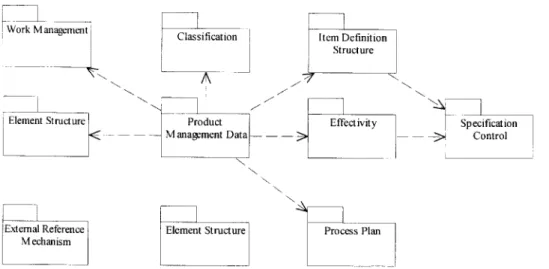
the standardized AIM for product data management and exchange, is more robust for implementing a STEP-based PDMS. Figure 1 illustrates the context and dependency of the UoFs defined in AP214. Compared with the functionality of PDMS, these data models fail to fulfil the requirement of PDMS product data represen-tation. To modify these static data models, the functionality representation and I/O interfacing should be enhanced. To modify and enhance the PDM-related data models in AP214, the data models in JPDM are employed. To demonstrate the variation between AP214 and JPDM, table 3 illustrates the scope based on the items derived from these two data models.
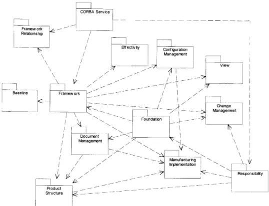
Figure 2 illustrates the context and dependency of 13 JPDM modules(Digital Equipment Corporation et al. 1998), including Responsibility, Foundation, Frame-work, Baseline, View, Document Management, Product Structure Definition, Effectivity, Change Management, Manufacturing Implementation, Configuration
Man-Figure 1. Dependency of the PDM-related UoFs defined in AP214. Table 2. Comparisons of PDM-related UoF in STEP and
PDM schema.
Index UoF element IR’s AP203 AP214 PDM
schema 1 Product identification * * ** ** 2 Product structure * * ** * 3 Shape representation * ** ** * 4 Product configuration * * ** * 5 Effectivity * ** * 6 Specification control * ** 7 Authorization * * * * 8 Source control * ** ** * 9 Work management * ** * 10 Document management * * 11 Classification * 12 Item property * ** * 13 Process plan *
Each star mark indicates the relative completeness, while empty indicates the lack of the data model of UoF element.
Table 3. Comparisons of JPDM and AP214 based on PDM’s functionality.
PDM’s functionality AP214 JPDM
Configuration management * *
Document management * *
Workflow/process management without
change management * *
Product structure management * *
Classification * * Project management * * Effectivity management * View management * Audit * Change management *
agement, and STEP module. Table 3 illustrates a comparison between the data models defined in AP214 and the functionality of PDMS. Furthermore, while JPDM focuses on data models for implementation of the PDMS functionality, AP214 provides robust data models for product data representation. The migration of these two data schema, which is discussed in section 3, ensures product data exchange and fulfils the PDM functionality requirement.
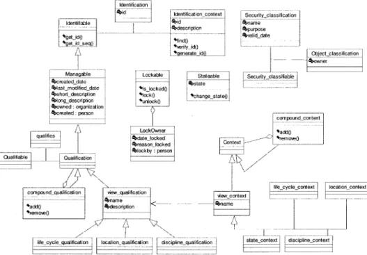
The foundation module in JPDM defines the essential class that controls the data management for subsequent PDMS classes. Six basic foundation classes (manageable, lockable, revisionable, iteratable, state-able and classifistate-able) have been defined from that which the PDMS objects will inherit. The baseline module in JPDM is the definition of items and their relationships that were established to reconstruct and audit their configurations. Moreover, to enforce appro-priate constraints, specific business or implementation rules can be added to the baseline. Similarly, the view module in JPDM provides a framework and explicit classes, which indicate applicable items and relation-ships, in specific contexts. With the qualification mechanism, users can access the context qualified by the specific view. The document module, derived from the framework module, controls the data vault and version control of documents. The engineering change
module is another significant factor for PDMS applica-tion in enterprises. That is, it supports companies’ requests, as well as the implementation and changes to products, documents, components, assemblies, manu-factured or purchased parts, processes, or suppliers. Finally, it includes issue collection, requesting change, implementing change, and notification of change. The framework, framework relationship, effectivity, config-uration management, responsibility, and product struc-ture definition modules can be applied to enhance the capability of those in AP214.
3. Migration of these PDM data schema
Migrating these data schema provides a standar-dized PDM data schema, which fulfils the functionality of PDMS, including the management of product structure, configuration, document, workflow/process management, effectivity, and engineering change. The classification, project management, and view function-ality are included in these data models. The proposed PDM data schema is not intended to standardize the implementation of the data schema residing in each PDMS. Rather, the proposal is a suggested conceptual data schema for each module. Varying applications and situations require additional models and modifications.
S.-C. Yeh and C.-F. You
4
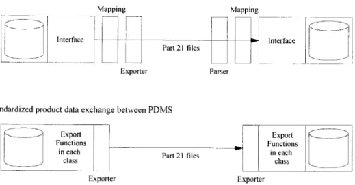
Since the PDM data schema adheres to the PDM-related one defined in STEP, data exchange and sharing can be implemented easily, without mapping. Figure 3 presents the product data exchange via standardized and traditional PDMS data schema. This, in turn, reduces the mapping effort, which is the most complicated task of system integration. The STEP exchange files, Part 21 files, are generated with the related member function of the data models. ‘Exporter’ defines the view and group of classes of the data schema for product data exchange. To define the required and common data structure for PDMS data items, the essential data models were organized (figure 4) via Unified Modelling Language (UML) (Booch et al. 1997). Migration of the data models, which is based on basic models, is discussed in subsequent sections. 3.1. Product structure management
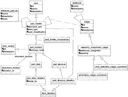
Within product structure management, data models facilitate the management of product definition and structure, such as Bills Of Material(BOM). As products change over time due to engineering change, the PDMS tracks the version, revision, effectivity, and design variation. ‘Revision’, as illustrated in figure 5, is defined and then extended to accomplish the product structure, which is a combined pair of part masters. In addition to standard BOM data, typical product structures contain attribute, instance and location information (McKay et al. 1996). As the kernel of the PDMS data schema, this module defines parts and the bill of material relationships between items for the
whole life cycle of the product data. A product/item may represent one of a variety of physical entities, such as material, part, sub-assembly, assembly, technical document, and tooling. A product definition may consist of engineering attributes, links between suppli-ers and parts, as well as CAD model references, and a list of the components required to assemble the part. These distinct components of the product definition are known as product data objects. Figure 5 shows the migrated data models for product structure manage-ment, which is based on the PDMS requiremanage-ment, and the standardized data models that are defined in AP214 and JPDM. The migrated data models define the association relationship of the part master, alternative part, optional part, and related parts revision. There-fore, via usage models, the substitute and BOM definitions can be attained.
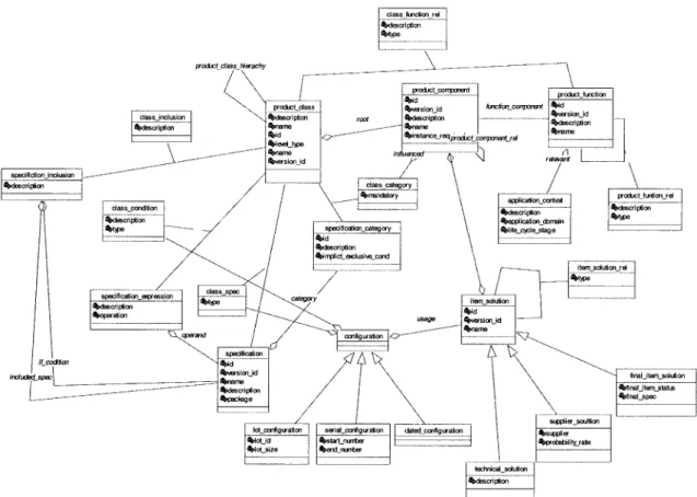
3.2. Configuration management and part classification Within configuration management, data models represent the product structure as well as the enterprise that is selling the product(Digital Equipment Corpora-tion et al. 1998). ConfiguraCorpora-tion Management(CM)is the process of defining and controlling a product structure and its related documentation. CM includes maintain-ing revisions and history information of all changes to a document or product(CIMdata Inc. 1997)thus defin-ing the distdefin-inguishdefin-ing features or specifications and rules used to select specific components based on these features. ‘Parts classification’ allows similar or standard parts, processes, and other design information to be
S.-C. Yeh and C.-F. You
6
Figure 4. Migrated core data models for item representation.
grouped by common attributes. Notably, this facilitates a more efficient mechanism for parts location, fewer re-designs and accurate inventories. Figure 6 illustrates the migrated data models, which are, in turn, based on the requirement and the standardized data models defined in AP214 and JPDM. The configuration information of a part includes product class, which is defined by function, specification and item solution. Furthermore, the dated lot number and serial number configuration are employed to define the configuration information. This can then be used to determine the effectivity of the item, as shown in figure 6.
3.3. Document management
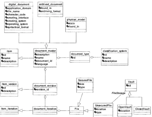
‘Document management’ provides the data models required to manage product-related documents. In-herited from item definition, document definition revises, iterates, and controls document versions. Combined with part masters, the relationship between document revision and part revision is linked. To perform a check-in, the document iteration is applied to make a copy of the original document. It then creates a new file, associates it with the Document
Iteration, and transfers the contents from the client to the PDM server. Finally, to accomplish data vaulting, the file is unlocked. Figure 7 illustrates the migrated data models for document management, which is based on the requirement and the standardized data models defined in AP214 and JPDM. Finally, to store the version and iteration information of documents, the data models define the document’s item master, revisions and iteration.
3.4. Workflow and project management
The data models of workflow management define the process specification and its relationships among the items produced, its manufacturing location and its engineering change order. Project management pro-vides a breakdown structures and allows resource scheduling and projects tracking. To provide an added level of planning and tracking, resources and managed data are linked. They represent process plans, version tracking process plans, process operations, and proper-ties of processes. Processes employed in a business are varied and modified over time (figures 8 and 9). The process plan models defined in AP214 are applied as
S.-C. Yeh and C.-F. You
8
Figure 7. Migrated core data models for document management representation.
the basis of the models. Notably, rather than dynamic process information, migrated data models focus on the static data storage. Repetitive workflow and processes can be employed in a PDMS to route data and packages automatically, as well as to control and monitor processes, and to provide management reporting. ‘Change control’ is a common workflow in most business. However, other workflows exist for design release management, engineering reviews, purchasing, problem tracking and resolution, and contract manage-ment.
3.5. Engineering change management
In an enterprise, engineering changes occur fre-quently. The engineering change data models in PDMS support the management of engineering change information. The most practical strategy for maintain-ing this information currently is to complete the corresponding tables. Items within said tables include engineering change issue (ECI), engineering change request (ECR), engineering change order(ECO), and engineering change notice (ECN) (figure 10). ECI represents an identified and collected engineering issue. The issue may derive from various sources, such
as other engineering change items, manufacturer, distributor, or customer, and may result in one or more ECRs. ECR represents a request for engineering change, which normally addresses one or more ECIs. An ECR is created after one or more ECIs are evaluated and deemed to be necessary technically. ECO repre-sents a directive to implement an approved ECR. The deliverable items are referred to as ECO deliverables, as shown in figure 10. This represents a single-order action item of a change or task to be complete, prior to ECO completion, that is, a work item. ECN represents a notification to manufacturers, vendors, marketing, the field, or other entities, and it describes the implemen-ted change of a single ECO. Normally, the ECN provides information regarding the effectivity of the ECO.
3.6. Effectivity management
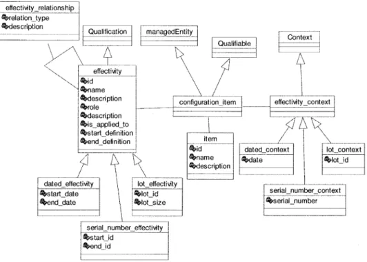
The data models of effectivity management define an indicator within a product structure that specifies the versions of the component part applied (CIMdata Inc. 1997). Generally, these indicators specify a range of dates, serial numbers or lot numbers. In addition, they are considered as a parent–child relationship within the
product structure. The corresponding models define the qualification and context models from the Views model of figure 11. This specifies a range in which an item revision, component, or other qualified item should be applied in production. Typically, engineering
specifies a planned effectivity; thus, to determine its validity, manufacturing will then use subsequent in-formation, such as the availability of parts. An effectivity range can be expressed through dates, through the serial number, or through lot numbers for the products
S.-C. Yeh and C.-F. You
10
Figure 10. Migrated core data models for change management representation.
being manufactured. As with other qualifications, effectivity may be applied to any qualified item, such as part revision, wherein it determines the range in which the revision can be conducted. Furthermore, it may be applied to a part structure usage relationship, in which case it ascertains that the component used is in that range.
The migrated View models (figure 12) provide a framework and explicit classes to indicate that items and relationships apply or qualify in particular contexts. A qualification is determined based on the purpose or a set of constraints. The view context specifies a particular constraint, conditions, or purpose.
4. Implementation of the proposed data schema
The benefits of applying the STEP standard to establish PDMS can be summarized by three factors. First, the object-oriented modelling language, EX-PRESS, aids the capture of complex PDMS information models. Secondly, STEP is an international standard that can reduce the incompatibility in product data exchange and sharing. Finally, the reusability of models can also reduce the development cycle and provide the extensibility for future development. The enabling technology, such as Standard Data Access Interface (SDAI) protocol, the wide-ranged standardized infor-mation model, and multi-language biding ability, develop the three-tiered layers of the STEP-based
system. The C++ models, derived from EXPRESS data modelling, in the conceptual layer and Object-oriented DataBase Management System (ODBMS)in the physi-cal layer, are identiphysi-cal to those in section 3. The communication barrier between these two layers can be reduced. The ensuing section proposes an implementa-tion approach for the data models in secimplementa-tion 3. 4.1. Implementing the migrated models into the conceptual
layer
Enterprise modelling is important in the integration of information systems that are applied in current enterprises. To capture the information within the enterprise, which ensures system integration, robust and flexible data models are required. The object-oriented modelling techniques applied here are EXPRESS and UML language. Since they are designed for information modelling, these two techniques perform data model-ling identically. UML notation is employed in the majority of engineer software and, with some Computer Aided Software Engineering (CASE) tools, such as Rational Rose, it can generate multi-language codes. To implement a tool-independent and functional STEP-based PDMS, the migrated data models were developed here (section 3). UML, which combines Booch, OMT, and CASE, is a new trend in object-oriented modelling languages. The migrated data models applied in the previous section demonstrate the UML notation.
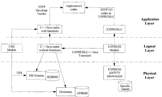
Prior to the release of EXPRESS language version 2, which enhances the behaviours and process definition of version 1, UML notation and C++ language was employed to implement the proposed data models (Spiby and Sanderson 1998). The benefits of object-oriented modelling language in-clude robustness, flexibility, extensibility, directness and reusability. In addition, it promotes the develop-ment of a STEP-based system. Via the support of an object-oriented programming language, data models will attach themselves to the development of a STEP-based system firmly. Currently, EXPRESS is employed to establish a STEP-based system, which designs the conceptual models, and then constructs the applica-tion layer via object-oriented and EXPRESS-C lan-guages, as shown in figure 13. To construct the physical layer of the system, the conceptual data models are translated to the Relational DataBase Management System (RDBMS), ODBMS, or EX-PRESS models management system. The bold lines in figure 13 indicate the solution applied here to develop the STEP-based system. To generate pro-grammable C++ codes and an object-oriented data-base (POET), the migrated data models, proposed in section 2, are placed into the UML modelling tool. Notably, the generated C++ codes are applied to develop the applications in the presentation layer, while an object-oriented database is ready for use. With this methodology, changes to the conceptual models reflect directly on the presentation and physical layers to ensure the consistency of the data models.
4.2. Implementing the physical layer of PDMS
Figure 13 reveals that the physical layer contains the construction of kernel database and network commu-nication media. Since the object-oriented conceptual data models in the conceptual layer affect the construction of the database, due to its representation of complex information models when developing the STEP-based system, the ODBMS provides a strong mechanism. For compatibility with relational databases and to ensure the effectivity of data retrieval, RDBMS is included after object-oriented modelling. Notably, this is the method used by most STEP-based system developers. The choice of either ODBMS or RDBMS is based on the complexity of the information to be stored. The former is suitable for complex data, such as PDM and CAD/CAM systems, whereas the latter is suitable for large quantities of data.
When RDBMS is adopted as the kernel of the STEP-based system, three issues arise. The first issue is the integration of legacy data (Bernosky 1997). However, Open DataBase Connectivity (ODBC) is a popular solution for this issue. By capturing the schema of legacy data and placing these new models into a STEP-based system, ODBC can then integrate legacy data into the ODBMS of our system. Conversely, via employing an ODBC driver of ODBMS, the data resided therein can also be shared by RDBMS.
To ensure product data exchange and sharing, the physical layer of STEP-based PDMS should be equipped with a data exchange method, an external shared database method, or a virtually shared database
S.-C. Yeh and C.-F. You
12
method. The data exchange method enables product data within a PDMS to be extracted and exchanged with physical files(An et al. 1995)in plain text. This method facilitates setting specifications and conducting tests, and is applicable to various systems. In this method, data within a PDMS can also be extracted as Part 21 files. The external shared database method is a method designed to access a common database between companies on a contract basis. In this method, data are copied from the PDMS into the common database and then shared. Within the virtually shared database method is a method through which the product data distributed among the PDMS of companies can be accessed concurrently for sharing (Urban et al. 1993, 1994, Tanaka et al. 1997). Furthermore, although the data shared are distributed physically, it appears to the user as if the distributed PDMS were virtually one. Thus, the virtually shared database may be the ultimate in product data sharing, which is intended to create a concurrent working environment.
Figure 14 illustrates the approach for constructing a STEP-based distributed database management system. The left-hand side indicates the generation of internal representation of EXPRESS codes, including the migrated data models of section 2. This can then be employed to construct the database, generate parser codes, and implementable C++ codes. The latter are compiled by ODBMS to append the management functions into original C++ codes. Similarly, the schema dictionary and its related codes are generated and managed by ODBMS. With the ODBC driver provided by ODBMS, the shared database environment can then be achieved (Spooner 1994, Ke and Yeh 1998).
Figure 15 presents three mechanisms of network communication with their operation methods,
includ-ing ODBC, database communication, and CORBA/ COM. These three are associated with an ODBMS that is recommended for STEP-based PDMS. To integrate all information systems within an enterprise, ODBC provides the link to these systems. Database commu-nication relies on the ODBMS. The most popular approach to address the PDMS server side is via TCP/IP protocol. Finally, to accomplish distributed PDMS, the CORBA/COM mechanism permits the distributed objects to communicate with each other.
4.3. Application layer
The primary issue with the application layer is to connect the physical layer application to those of the conceptual layer. The effectivity of data management and compatibility with STEP are always in opposition. However, one solution is the implementation of a STEP-based system via ARM and AIM (Rahimifard and Newman 1996). Gradually, popular database preprocessor tools resolve this shortcoming, so that prototyping applications can be developed rapidly and then be connected to target the database easily. The application layer, or presentation layer, is accom-plished by referencing models within the conceptual layer to adopt various requirements. Essentially, a STEP-based PDMS has two main attributes in this layer, which include flexible modelling and better communications interface. Notably, the former adopts distinct requirements from varying enterprises. It recommends changes to conceptual models, which produce a flexible data structure and instances in database. The latter focuses on the establish-ment of a network communication interface. PDMS
must manage and share information throughout the entire enterprise; thus, the communication interface is important for PDMS. Since the STEP-based system is an object-oriented system, most communication inter-faces rely on Java, CORBA, or DCOM to achieve a distributed environment.
STEP specifies SDAI, which realizes an integrated system by sharing the AIM product data of applications such as a CAD system and PDMS (Goh et al. 1994, Botting and Godwin 1995). SDAI is an Application Programming Interface(API), which stores and shares the product data independent of the physical layer of the system. Since SDAI operates via EXPRESS, it can be used effectively in productivity or practical utilization. The new approach applied to manage STEP data is via a High Level Data Access Interface (HLDAI), which is a user-friendly interface with an application view. Via the HLDAI parts generated, the STEP database, without either SDAI or AIM, is accessible. A STEP data exchange system is constructed according to APM, which is a data structure definition of application, such as CAD or PDMS. Rather than SDAI or HLDAI to develop STEP-based PDMS and manage the corre-sponding information, the object-oriented manage-ment mechanism, including OODBMS or the serialization mechanism of object-oriented language, was employed here.
4.4. Case study
To verify our migrated data models, a PDM system with the proposed data models in this paper was
implemented and applied in two manufacturing in-dustries, A and B. Industry A had the entire repository system, while industry B, the first-tiered supplier of industry A, had merely a portion of the STEP-based data exchange. In industry A, PDMS managed docu-ments, drawings, product structure, configuration information, classification, workflow, and engineering change. Through the STEP-based exchanger applica-tion, these two industries collaborated to enable product data co-design.
It should be noted that the co-design between these two industries with different CAD and operation systems was the application scenario. Industry A employed a conceptual design or engineering change case, and then transferred the information, including CAD models and related technical data, to industry B. Industry B evaluated the conceptual design or en-gineering change and then responded with designs or recommendations. The process was repeated until the final design was approved and the manufacturing and ordering information was readied for production. Industry A translated the engineering data and CAD models of a product via a STEP-based interface and then forwarded them to industry B. Figure 16 illustrates the working process of the PDMS. Based on the data models proposed here, each application had a corre-sponding conceptual data model. The data models were translated and built into the Oracle databases of the repository system. To ensure consistency, the databases incorporated the data structure, schema, and definition of the migrated data models. Finally, based on these databases, the repository applications were developed.
S.-C. Yeh and C.-F. You
14
5. Discussion and conclusions
The migrated data schema discussed in section 3 fulfils the run-time requirement of the practical functionality of PDMS. However, to generate STEP P21 files, it also resolves the mapping issue between ARM and AIM within product data exchange. To standardize and thus fulfil the functionality of PDM, these data schema were migrated. The proposed models abstract the data models from AP214 and JPDM. Therefore, this kind of system can be employed to meet the requirement of product data exchange and sharing. Obviously, the urgent re-quirement of concurrent engineering is magnified by the requirement of product data exchange and sharing. Figure 17 illustrates the product data
Figure 16. Working process of the applications of the repository system.
Figure 17. Three approaches for product data exchange and sharing in PDMS.
Figure 18. Codes generating from proposed migrated data models of PDMS.
exchange and sharing of the proposed standardized data schema. However, to ensure this, integrated, standardized, applicable product data models are required. Notably, the proposed data models can accomplish this requirement.
Figure 18 illustrates PDMS implementation via the migrated data models. With UML modelling tools, such as Rational Rose, the working form of the proposed data models can be generated. The selection of the programming language depends on PDMS developers. To accomplish thorough informa-tion exchange and sharing between departments, within an enterprise and between enterprises, the data consistency of PDMS plays a significant role. The PDM schema, support by ProSTEP and PDES, Inc., provides essential data integration for config-uration management information. A STEP-based PDM-related data schema was proposed to fulfil the functionality requirement and ensure the product data exchange and sharing, which in turn promotes concurrent engineering and systems inte-gration.
References
AN, D. LEEP, H. R., PARSAEI, H. R., and NYALUKE, A. P., 1995, A
product data exchange integrated structure using PDES/ STEP for automated manufacturing application. Computers
Industry Engineering, 29, 711–715.
BERNOSKY, L., 1997, Turning legacy data into enterprise
information. Proceedings of 21st Century Commerce & CALS
EXPO International Conference, Orlando, Florida, October
1997.
BOOCH, G., JACOBSON, I., and RUMBAUGH, J., 1997, The Unified
Modeling Language, Documentation Set 1.1(Rational). BOTTING, R. N., and GODWIN, A. N., 1995, Analysis of the STEP
standard data access interface using formal methods.
Computer Standards & Interfaces, 17, 437–455.
CHAXEL, F., BAJIC, E., and RICHARD, J., 1997, Mobile databases
nodes for manufacturing information management: a STEP based approach. The International Journal of Advanced
Manufacturing Technology, 13, 125–133.
CHEN, Y. M., and HSIAO, Y. T., 1997, A collaborative data
management framework for concurrent product and process development. International Journal of Computer
Integrated Manufacturing System, 10, 446–469.
CIMDATA INC., 1997, Product Data Management: The Definition
(USA: CIMdata Inc.).
CZERWINSKI, A. S., and SIVAYOGANATHAN, K., 1994, Development of
CIM applications from PDES/STEP information models.
Concurrent Engineering: Research and Applications, 2, 133–136.
DASSAULT SYSTEMES., 1997, Product Data Management Enablers
Proposal, Revision 1.0, 14 April.
DIGITAL EQUIPMENT CORPORATION, FUJITSU LIMITED, INTERNATIONAL
BUSINESSMACHINES CORPORATION, MATRIXONE, INC., METAPHASE
TECHNOLOGY DIVISION, STRUCTURAL DYNAMICS RESERARCH CORP.,
and SHERPA CORPORATION, 1997., Product Data Management
Enablers Proposal, Revision 1.0, 15 April.
DIGITAL EQUIPMENT CORPORATION, FUJITSU LIMITED, INTERNATIONAL
BUSINESSMACHINES CORPORATION, MATRIXONE, INC., METAPHASE
TECHNOLOGY DIVISION, STRUCTURAL DYNAMICS RESERARCH CORP.,
and SHERPA CORPORATION, 1998., Product Data Management
Enablers Joint Proposal, 2 February.
FUJITSU LIMITED, 1997, Product Data Management Enablers
Proposal, Revision 1.0, 14 April.
GOH, A. HUI, S. C., SONG, B., and WANG, F. Y., 1994, A study of
SDAI implementation on object-oriented databases.
Computer Standards & Interfaces, 16, 33–43.
GU, P., and CHAN, K., 1995, Product modeling using STEP.
Computer-Aided Design, 27, 163–179.
ISO, 1994, ISO 10303: Product data representation and exchange – Part 41: Integrated generic resource: Funda-mentals of product description and support, 1994. ISO, 1994, ISO 10303: Product data representation and
exchange – Part 42: Integrated generic resource: Geometric and topological representation, 1994.
ISO, 1994, ISO 10303: Product data representation and exchange – Part 43: Integrated generic resource: Repre-sentation structures, 1994.
ISO, 1994, ISO 10303: Product data representation and exchange – Part 44: Integrated generic resource: Product structure configuration, 1994.
ISO, 1994, ISO 10303: Product data representation and exchange – Part 203: Application protocol: Configuration controlled design, 1994.
ISO, 1997, ISO 10303-214 CDII – Core Data for Automotive Mechanical Design Processes, 1997.
KE, S. K., and YEH, S. C., 1998, The pilot system for STEP-based
product data exchange. Proceedings of CALS/EC EXPO Japan, Tokyo, November 1998, pp. 197–206.
MCKAY, A., ERENS, F., and BLOOR, M. S., 1996, Relating product
definition and product variety. Research in Engineering Design,
2,63–80.
METAPHASE TECHNOLOGY, INC., 1997, Product Data Management
Enablers Proposal, Revision 1.0, 14 April.
PROSTEP and PDES, INC., 1998,Unified PDM Schema, Version 1.1.
RAHIMIFARD, S., and NEWMAN, S.T., 1996, A methodology to
develop EXPRESS data models. International Journal of
Computer Integrated Manufacturing System, 9, 61–72.
REDDY, Y. V. R., SRINIVAS, K., JAGANNATHAN, and KARINTHI, R., 1993,
Computer support for concurrent engineering. Computer,
26,12–16.
SHERPA CORPORATION, 1997, Product Data Management Enablers
Proposal, Version 1.4, 12 April.
SPIBY, P., and SANDERSON, D., 1998, Introduction to EXPRESS 2.
ISO SC4/WG10 Document N58, 11 June.
SPOONER, D. L., 1994, An object-oriented product database
using ROSE. Journal of Intelligent Manufacturing, 5, 13–21. TANAKA, Y., MASEGAWA, K., YATABE, S., and OBETA, K., 1997,
Product data sharing among distributed heterogeneous PDMs. Proceedings of CALS EXPO International, Tokyo, November 1997.
S.-C. Yeh and C.-F. You
URBAN, S. D., SHAN, J. J., and ROGERS, M. T., 1993, Engineering
data management archieving integration through database technology. Computing & Control Engineering Journal, 4, 119– 126.
URBAN, S. D., SHAN, J. J., ROGERS, M., JEON, D.K., RAVI, P., and
BLIZNAKOV, P., 1994, A heterogeneous, active database
architecture for engineering data management.
Interna-tional Journal of Computer Integrated Manufacturing System, 7,
276–293.
WU, J. K., LIU, T. H., and FISCHER, G. W., 1992, An integrated
PDES/STEP based information model for CAE and CAM applications. The Second International Conference on