~ Pergamon
J. Franklin Inst. Vol. 334B, No. 2, pp. 213 232, 1997 Copyright ( 1997 The Franklin Institute P I I : S0016M)032(96)00077-4 Published by Elsevier Science Ltd Printed in Great Britain 0016 0032/97 $17.00+0.00
Design of General Structured Observers for Linear
Systems with Unknown Inputs
b y S H A O - K U N G C H A N G
M e c h a n i c a l Industry Research Laboratory, Industrial Technology Research Institute, Hsinchu, Taiwan 300, Republic o f China
W E N - T O N G Y O U and P A U - L O H S U *
Institute o f Control Engineering, National Chiao Tung University, Hsinchu, Taiwan 300, Republic o f China
( R e c e i v e d 6 N o v e m b e r 1994," accepted 16 June 1996)
ABSTRACT : Using the framework o f the general structured (GS) observer, we present a straight- forward procedurefor designing an unknown input observer (UIO) jor a linear O'stem subject to unknown inputs or uncertain disturbances. The set o f all GS observers insensitive to unknown inputs is derived in this paper. Moreover, an extension o f the UIO, called the extended UIO, is' developed to estimate both the system state and the unknown input simultaneously. We show the existence conditions o f a stable UIO are the same as those o f a stable left inverse system. In addition, well- conditioned designs for both the state and unknown input estimations are also explored. Conditions o f transmission zeros reveal that to achieve a stable UIO, the uncertain system should be minimum- phase. To overcome this restriction, we adopt a two-delay output stabilized method to design the stabilized UIO without implementing extra sensors. Experimental results Jor a DC servo motor system demonstrate the applicability o f the proposed methodologies. Copyright @ 1997 Published by Elsevier Science Ltd
L Introduction
The reconstruction of the state of a dynamic system whose input is not measurable is of special importance in practice, since there are m a n y situations where plant dis- turbance occurs or part o f the input of the system is inaccessible. Under such cir- cumstances, a conventional observer that requires knowledge of all inputs cannot be used directly. The u n k n o w n input observer (UIO) was developed to estimate the state of an uncertain system despite the existence of u n k n o w n inputs or uncertain disturbances. This U I O has received considerable attention f r o m m a n y researchers (1- 9). In real applications, the U I O achieves better control performance and m o r e reliable
* Author to whom all correspondence should be addressed. 213
214 Shao-Kung Chang et al.
diagnostic performance than a conventional observer. Recently, in addition to state estimation, the use of the U I O in fault diagnostic and process monitoring systems has also attracted much attention (10-13).
Most previous papers on UIOs employed the design for a reduced-order UIO, e.g. as given in Refs (1-7). However, Yang and Wilde (7) demonstrated that the full-order U I O yields a faster rate o f estimated convergence than the reduced-order UIO, because the full-order UIO does not need to transform states and thus the dynamic restriction imposed by the system matrices is minimized. Although Yang and Wilde (7) used straightforward matrix operations to provide a practical design method, their design still involved considerable computational complexity. In this paper, unlike other approaches which are based on the Luenberger observer, we design a full-order UIO based on the configuration o f the general structured (GS) observer proposed by Cheok et al. (14). This approach leads to a more concise and straightforward formulation of the U I O problem. We obtain the set o f all GS observers insensitive to unknown inputs by applying the M o o r e - P e n r o s e generalized inverse. Necessary and sufficient conditions for the existence of a stable full-order G S - U I O are provided, and it is shown that these conditions are the same as the existence conditions for the UIOs provided in Refs (5, 9). It should be emphasized that the proposed UIO design is similar to the design o f a conventional observer, which requires only pole-placement techniques. In real appli- cations, the U I O still cannot exactly cancel out the undesired plant dynamics, because o f those unstructured uncertainties and noise. Thus, we also consider the design of a well-conditioned UIO to provide progressive robust estimation for system monitoring and fault diagnosis.
Since the existence conditions are provided in terms o f transmission zeros, similar to the existence conditions o f the inverse system problem. We also propose an extended version o f U I O for estimating both system states and unknown inputs. We show in this paper that the left inverse system is an extension of the UIO. The estimation of unknown inputs can be further applied to accommodate process uncertainty so as to produce robust control systems. Thus, the U I O system can be directly or indirectly applied to many aspects of the analysis and design of multivariable control systems. Conditions o f transmission zeros also reveal that the given uncertain system should be minimum-phase to obtain a stable UIO. To overcome this restriction without implementing additional sensors, we adopt a stabilized method based on the technique o f two-delay output control proposed by K a k u et al. (15). The stabilized U I O design method entails that a stable UIO can generally be achieved without extra sensors.
We have implemented the proposed U I O on a D C servo m o t o r system and on a servo table system with external loading. The dominant disturbance in the first system is friction and that in the second system is external loading. Experimental results indicate that the estimations of states and disturbances are in good agreement with measurements, thus confirming the applicability of the UIO methodologies developed here.
The following notation will be used in this paper: a ,= b means a denotes b; E ,= the field o f real numbers; C ~= the field o f complex numbers; ] v ] .'= Euclidean norm of vector v; IlAll.'=spectral norm o f matrix A; C ~ . ' = { z ~ C ] l z l < l } ; C~.'=
{z
~ CII z l/>
1}; 1.
,= the unit matrix of dimension n; A a-,= the transpose of A; A + = (A'rA)- ~A v .'= the M o o r e - P e n r o s e generalized inverse o f A.G e n e r a l S t r u c t u r e d O b s e r v e r s f o r L i n e a r S y s t e m s 215 I L Design of the General Structured UIO
2.1. Full-order design
We consider a deterministic linear time-invariant discrete-time system described by
Xk + l = AXk + BUk + Edk (1 a)
Yk = Cxk (1 b)
where Xk E ~" is the state vector, Uk ~ ~P is the measurement input vector, dk ~ ~r is the unknown input vector, Yk ~ ~ " is the measurement output vector, and k denotes the discrete-time variable. A, B, E and C are constant matrices o f appropriate dimensions. Without loss of generality, we assume that E has full column rank and C has full row rank, i.e. rank(E) = r and rank(C) = m. Note that the term Edk in Eq. (la) can also be used to represent uncertainties acting upon the system, the so-called structured uncertainties, which may incorporate unknown time-variancy, unknown nonlinearity and uncertain coefficients (13). F o r the system in Eq. (1), the general structured (GS) observer proposed by Cheok et al. (14) is as follows:
YCk+ 1 = (A -- L l C A - L2 C):~k + ( B - - L 1CB)uk + L ayk+ ~ + L z y k (2) where ~k~ ~" denotes the estimated states, LI and L2 are dimensionally compatible constants to be determined. By setting L2 = 0, we obtain a full-order current update observer. Similarly, by setting L~ = 0 we obtain a full-order predicted observer (14). By Eqns (1) and (2), the estimation error equation is
ek+ ~ = Xk+ ~ -- :fk+ ~ = (A -- L~ C A -- L z C)ek + ( E - - L~ C E ) d k . (3) The first major goal of this paper is to design a full-order unknown input observer (UIO) based on the structure of Eq. (2) for the system in Eq. (1). The U 1 0 asymp- totically estimates the state vector Xk without knowledge of the unknown input signals dk. F r o m Eq. (3), we conclude that an UIO can be achieved if and only if the following two conditions are satisfied simultaneously:
(A1) the matrix ( A - L~ C A - L2 C) is asymptotically stable; (A2) L j C E - E = O.
Condition (A1) guarantees that the observer will be asymptotically stable. Obviously, if condition (A2) is satisfied, then the observer is independent o f the unknown input disturbance dk. The following lemma provided in Ref. (16) establishes a condition on the given system which ensures that the disturbance insensitivity condition (A2) can be satisfied.
t e m m a !
The equation L 1 C E --- E is consistent if and only if rank(CE) = rank(E) = r. R e m a r k 1
The condition of Lemma 1 is commonly adopted in the observer design for a linear system with unknown inputs. This necessary condition for the existence of a observer not sensitive to unknown inputs implies that specified state variables must be measured or at least appear as part o f the output. That is, if E has only r nonzero rows, they
216 Shao-Kung'Chan9 et al.
must be independent and then all corresponding r state variables must appear in the output yk. Motivated by this condition that unknown input effects should be contained in the output signals, we find that it is possible to estimate the unknown input signals by means of an UIO. The associated results for the unknown input estimation are presented in Section III of this paper. Also, by applying this condition for various sets of measurements, one can choose the minimum set of measurements necessary to observe the behavior of a system with unknown inputs.
Now, if rank(CE) = rank(E) = r, the set of all solutions L~ for condition (A2) can be given by
{L1 } = {E(CE) + +/S, [Ira - (CE)(CE) +][/S, is arbitrary} (4) where (CE) + = [(CE)X(CE)] ~(CE) a- is the Moore-Penrose generalized inverse. Equa- tion (4) entails that the matrix (A -- L~ CA - L2 C) becomes
A - L I C A - - L 2 C = A - [ L 2 /~, ] [cC~]
where ,7t=A--E(CE)+CA. Therefore, condition (A1) is satisfied, that is,
( A - L~CA - L 2 C) can be stabilized, if and only if the pair
is detectable. It is easy to show that the pair (C, A) is completely observable (detectable) if and only if the pair
is completely observable (detectable). The following theorem summarizes the above derivations.
Theorem I
The general structured observer (2) is a stable UIO for the uncertain system (1) if and only if the following two conditions are satisfied:
(i) rank(CE) = rank(E), and
(ii) the pair (C, ,4) is detectable. •
The following lemma and corollary show that the detectability (observability) of the pair (C, A) is related to the transmission zeros of the triple (C, A, E).
Lemma 2
If rank(CE) = rank(E), then the pair (C,.~) is detectable if and only if the triple (C, A, E) has no unstable transmission zeros. (For the proof see the Appendix.)
Corollary
If rank(CE) = rank(E), then the pair (C, A) is observable if and only if the triple (C, A, E) has no transmission zeros.
General Structured Observers for Linear Systems 217
With the above results, we obtain the following theorems.
Theorem H
The general structured observer (2) is a stable U I O for the uncertain system (1) if and only if
(i) rank(CE) = rank(E); and
(ii) the triple (C, A, E) has no unstable transmission zeros. •
Theorem III
F o r the uncertain system (l), there exists a GS U I O whose eigenvalues can be freely assigned if and only if
(i) rank(CE) = rank(E); and
(ii) the triple (C, A, E) has no transmission zeros. •
In the above theorems, condition (i) ensures that the observer is insensitive to the u n k n o w n input and condition (ii) ensures that the uncertain system is detectable (observable) by the UIO.
Moreover, by Eq. (4), we can write the set of all u n k n o w n input insensitive GS observers in the following form:
-~k +, = ( 2 - £~ c ~ - L2 C)~k + ( ~ - £, C~)uk + (E(CE) +
+I~ [Ira- CE(CE)+])yk+, + Lz)'k (5) where A = A - E ( C E ) + C A , 13 = B - E ( C E ) + C B , £~ and L2~ E,×m are arbitrary for
observer performance design. T h a t is, the desired observer response can be achieved by assigning a suitable eigenstructure through the design of £1 and Lz.
Remark 2
The existence conditions for a full-order GS U I O given in T h e o r e m s II and III are the same as those obtained by the other authors mentioned earlier, which are derived by the use of Luenberger observer. Actually, the rank condition in L e m m a 1 requires that the n u m b e r of outputs m be greater than the n u m b e r of u n k n o w n inputs r. T h e o r e m III requires that m be greater than r to obtain a system (C, A, E) without transmission zeros when the rank(CE) is maximal. Furthermore, if the observed system contains unstructured modeling errors or m e a s u r e m e n t noise in addition to u n k n o w n inputs, the formulation of Eq. (5) entails that some conventional observer design techniques, e.g. eigenstructure assignment and noise filtering, can be directly applied to the present U I O design.
Remark 3
T h e o r e m 11 shows that only systems (C, A, E) with stable transmission zeros m a y have a stable UIO. Conversely, a system (C, A, E) with a transmission zero outside or on the unit circle of the complex plane has an unstable UIO. In classical control terminology, such systems are said to be non-minimum-phase. This result indicates that the U I O m a y be related to an inverse system. We will show in Section III that the
218 Shao-Kun9 Chan 9 et al.
existence conditions for a stable U I O are the same as those for a stable left inverse system. Also, from the theory o f transmission zeros, as presented in Refs (6, 17), one has that if r = m then almost all triples (C, A, E) have n - - m finite transmission zeros and if r # m, then almost all triples (C, A, E) generally have no transmission zeros. By the above statements and a condition given by Syrmos (6), which shows that rank(CE) = rank(E) is generic in C and E when m > r, we may conclude that the problem of UIO design with arbitrary pole-assignment is generally solvable if m > r.
Remark 4
By defining a new state zk = ~ / c - L~yk, we obtain the following alternative equivalent expression of the GS observer:
2 k + 1 = Qzk + Gy~ + Huh where
Q = A - L I C A - L z C
G = L2 + A L l
--LI CALl
- L 2 C L 1 H = B - L I C B .The observer output equation is given by
xk = zk + Llyk.
Note that the above equivalent observer is important in the correspondence between the discrete-time and the continuous-time G S - U I O design. All the derived results for discrete-time systems can thus be valid for continuous-time systems. Although the present derivation is in discrete-time domain with the difference term, this equivalent structure allows the proposed GS observer to be applied to continuous-time systems without the differential term (18).
Comment 1 (solutions f o r the reduced-order UIO)
Although the set o f all unknown input insensitive GS observers in Eq. (5) is derived by the formulation of the full-order design, Eq. (5) is indeed implicitly involved in the solutions for the reduced-order UIO. We assume C = [0 I,,] for simplicity and express Eq. (la) in the following partitioned form:
Bl
[Xl,+I]_FA,I Al=IFx,,]+ [,=],,+
LX2k+JJ LA21 AnJLx=*J
In a similar manner, by taking the partition of matrices
i-A,,
~'~,27
~ F # 1 7l
General Structured Observers f o r Linear S y s t e m s and computing (CE) + = E~-, we rewrite Eq. (5) in the following form:
[
2'k+ll=[--2''--I21'2~l .x,~-£1I.C~2-L~,][2,~+F~,-£1I~2q
-/2k+,J
_.¢~,-£,2-X~, .¢22-[,~.¢22-L22JL22kJ
LE=-i, #RJ
"'
219
+ lYk+l
+ I_E~E; +L~(Im-E~E2 ) d LL~2y "
Setting/£12 = Im and L22 = 0 yields 22k+ l = Yk+ 1
21k+l = (lZ~l 1 --/£11A21 )-~lk -]- (B1 --/£11/~2)Uk 't- (ZZll 2 --/£11 ~z122)Yk + [ E 2 E I + IS12(Im-- E z E f )]yk+,
which is the set of all minimal-order UIOs, and/£1~ is the design parameter for the observer response.
2.2. Well-conditioned design
One o f the most important applications o f UIOs is in the field o f model-based fault diagnosis and process monitoring. Although a UIO can achieve perfectly unknown input decoupling, in a general realistic case it still cannot cancel out the plant dynamics exactly because of modeling errors, parameter uncertainties and measurement noise. Since robustness of the estimation to errors in the process model is essential for diagnostic and monitoring applications, our current task is to further enhance the robustness of the UIO derived in Eq. (15), in the presence of unstructured modeling errors in the system model. Here, in addition to structured unknown inputs, we assume that there are unstructured modeling errors AA and z~B in matrices A and B. That is, we consider a class of uncertain dynamic systems modeled by the following equations: Xk+ 1 = (A + A A ) x k + (B + AB)Uk + Edk (6a)
Yk = CXk. (6b)
Using the GS observer (2) leads to the following estimation error equation:
ek+, = (A -- L, C A - L 2 C)ek + ( E - - L l C E ) d k q- ( A A x k + ABuk). (7) For unknown input decoupling, we assume that conditions (i) and (ii) of Theorem II hold. Now, by giving L1 in the form of Eq. (4) for unknown input decoupling and letting Ad = (A - L l CA -- L2 C) = (A - LI CA - L2 C) and Ak = (AAxk + ABuk), we obtain the following dynamic equation for the estimation error:
e~+ i = A¢lek 4- Ak (8)
subject to the initial condition e0 = x0 - 2 o . F o r the case of distinct eigenvalues, the solution of Eq. (8) yields
220
Shao-Kun# Chang
et al. kek : A~,eo+ Z AdlAk-i
i=1 k= Q A k Q - ' e o + ~ Q A i - ~ Q
~Ak ~
(9) i=1where Ad =
QAQ ~
with Q is the modal matrix corresponding to Acl and A is a diagonal matrix with the eigenvalues of A¢~ as the diagonal elements. Taking the norms of both sides ofEq. (9),
we obtain[ek[<~llQ[l'l[Q-1]['{ I [ A k l l ' l e ° ] + ~ [ [ A i
i:1 ' [l']Ak-i] }~i--I ] A k _ i [
=
~c(Q). ~k. leo I + =
(lO)where ~:(Q) .'= II Q II" It Q - i II is the condition number of Q and II A k II = ~k with ~ being the observer pole farthest from the origin point in the complex plane, here assumed to be located inside the unit circle. Equation (10) provides a guideline for enhancing the robustness of a UIO. It suggests that in this case the UIO gain matrix, /f~ and L2, should be chosen to minimize the condition number ~:(Q), in addition to yielding the desired eigenvalues. As for eigenstructure assignment, the objective in eigenvector selection here should be to make the eigenvectors as nearly mutually orthogonal as possible, so as to reduce the estimation error bound. Furthermore, based on Eq. (10), a multiple objective optimization technique proposed in Ref. (19) can also be directly applied to the design of the robust UIO for system monitoring.
Remark 5
Numerical algorithms for minimizing the condition number by eigenvector assign- ment have been proposed by Kautsky
et al.
(20). They explored iteration and opti- mization methods to approximate the optimal solution. However, the numerical stability provided by their iteration algorithm depends on the initial condition, i.e. an unsuitable initial condition may make the iteration process oscillate or diverge; a satisfactory solution is not always guaranteed. Another optimization method of par- ameterization also in Ref. (20) guarantees the computational stability but seems too complex for real applications and computations. By parameterizing the set of all achievable eigenvectors for assignment, Shenet al.
(21) developed a simple but con- vergent numerical algorithm to obtain approximate optimization, in which the design criterion of fault diagnosis and system monitoring is involved in the approximations for well conditioned eigenvector assignment.III. Extended
UIO Design for State and Unknown Input EstimationBy Theorem II, it is clear that only systems (C, A, E) without unstable transmission zeros in the region outside the unit circle of the complex plane have stable UIOs. In classical control terminology such systems are said to be minimum-phase. Motivated by this criterion, we consider the problem of inverse system construction. There are
G e n e r a l S t r u c t u r e d Observers f o r L i n e a r S y s t e m s 221 several methods for estimating the unknown deterministic input added to the plant, as given in Refs (22-24). As shown in Ref. (23), a system has a stable left inverse system if and only if its transfer matrix is full column rank and it contains no unstable zeros. Theorem II shows that the existence conditions for a stable UIO are sufficient to guarantee the existence of a stable left inverse system for unknown input estimation. Therefore, drawing on the concept o f the one-delay inverse system, as shown in Refs (22, 24), we propose the following extended UIO to estimate both system states and unknown inputs, if the unknown inputs need to be estimated.
T h e o r e m I V
An extended UIO represented by the following equations
ffk + l = ( A - - L 1 C A - - L2 C)~c~ + ( B - - L j CB)uk + L l y k + 1 ~- L2yk (i l a)
dk+, = ( C E ) + ( Y k + , - - CAYck - C B u ~ )
(1 lb)
can asymptotically observe the state and the unknown input o f the system represented by Eq. (1) if and only if(i) rank(CE) = rank(E); and
(ii) the triple (C, A, E) contains no unstable transmission zeros. P r o o f
(Necessary) Since conditions (i) and (ii) o f this theorem are the same as the necessary and sufficient conditions for the stable UIO, the above two conditions are at least necessary conditions for the present extended UIO. (Sufficient) Since conditions (i) and (ii) o f this theorem lead to a stable UIO being obtained, i.e. Xk--~k = ek ~ 0, and ( C E ) + ( C E ) = L , by Eq. (1) Yk + 1 = C A x k + CBuk + CEdk we then obtain dk = ( C E ) + yk + l - ( C E ) + C A x k -- ( C E ) + CBuk. Therefore, ~lk '= dk+, - dk = ( C E ) + C A e k . (12) For e~ ~ 0, we conclude that dk+~ --, d~. Thus, if x0 = ~0, then dk+~ = dk, which is the
one-delay left inverse system shown in Refs (22, 24). •
C o m m e n t 2 (a well-conditioned design f o r u n k n o w n input e s t i m a t i o n )
A case with short sampling time will produce a large (CE)+. As a result, by Eq. (12), it will also generate a large error for unknown input estimation. To overcome this difficulty, we may further modify the input estimation equation (1 lb) as follows:
dk+~ = ( C E ) + [Yk +, - C A x k -- CBu~] + L3 (C~;:k --Yk) (13) where L3 ~ ~r×,, can be designed to reduce the estimation error bound. Now, by Eq. (13), the input estimation error equation can be expressed as follows:
222 Shao-Kun9 Chan9 et al.
qk = dk+, -- d~ = (L3 C - (CE) + CA)ek. Thus,
Ink } >~ II(L'3C-(CE)+CA)I1"1 ek I.
T o minimize
II
L3 C - - ( C E ) + CAII
and thus suppress the amplitude o f qk, we can obtainL 3 a s
L3 = (CE) + (CA C T) (CC T)- '. (14)
R e m a r k 6
We have shown that a stable left inverse system exists if and only if a stable UIO exists. However, Eqns (11) and (13) provide more general implementations o f the inverse system. It can be shown that the observer for estimating system states and unknown inputs proposed by Gleason and Andrisani (24) is only a special case of the implementation of Eqns (11) and (13). Note that in Ref. (24), it is shown that the gain o f an optimal dead-beat input estimator can be determined by implementing the estimator as a Fisher filter.
R e m a r k 7
Drawing on the results for the GS UIO, we propose the following dynamics for estimating both the system states and unknown inputs by designing L2 to result in the desired eigenvalues for the observer system:
-~k+l = (14 - - E ( C E ) + CA - L 2 C ) ~ k + E(CE)+ yk+~ H- L 2 y k + ( B - E ( C E ) + C B ) u k dk+, = (CE) + (Yk+l - - CAaCk - CBuk)
o r
dk+, = (CE) + {Yk+l -{- CA [ c T ( c c T) -1 C - - I.]Yck -- CBuk -- C A C T ( C C T) -*Yk}. IV. Design o f the Stabilized UIO
The condition rank(CE) = rank(E) means that the corresponding states coupled with unknown inputs must be obtainable from the measurement outputs. Moreover, it implies that the number o f output signals should be no less than the number of unknown inputs, i.e. m >/r. In the case where m = r, the observability matrix of the pair (C, A) will be equal to C only. This condition always leads to a non-minimum-phase system and thus a stable UIO or extended UIO cannot be found. Therefore, additional sensors must be implemented to increase the number o f output signals so as to cope with this problem, as indicated in Remark 3. In general, if the number of sensors in a system is increased, the estimation accuracy can also be improved, because o f the extra infor- mation extracted from the additional sensors. However, implementing extra hardware sensors may not be practical in real applications, and it also increases the economic cost. Here, we adopt a stabilized method for the proposed UIO that avoids the non- minimum-phase problem and does not require extra hardware sensors. This method is based on the technique o f two-delay output control proposed by K a k u et al. (15). Here,
General Structured Observers f o r Linear S y s t e m s 223 we consider only the case o f r = m, since the problem of n o n - m i n i m u m - p h a s e always arises in a system with r = m; however, the present results can be extended to other cases with the same problem. We first consider a continuous-time system expressed by
£(t) = Acx(t) + Bcu(t) + Ecd(t) (15a)
y(t) = Cx(t) (15b)
where y(t) and d(t) e ~r and the pair (C, Ac) are assumed to be observable. F o r input estimation, the continuous-time extended U I O requires derivative operations, which makes it unsuitable for practical implementation. Thus, we can use the digital extended U I O , allowing some delays. The corresponding discrete-time system of Eq. (15) with sampling time T can be written as
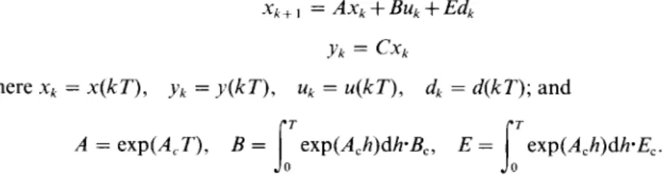
Xk + 1 = AXk + BUk + Edk (16a)
Yk = CXk (16b)
where Xk = x ( k T ) , Yk = y ( k T ) , Uk = u ( k T ) , dk = d ( k T ) ; and
f;
t
A = e x p ( A ~ T ) , B = exp(Ach)dh'Bc, E = exp(Ach)dh'Ec.
0
Without loss of generality, we also assume that C has full row rank and E has full column rank. To overcome the problem of unstable transmission zeros, an auxiliary output, previously introduced in Refs (15, 25), is employed as
Zk = z ( k T + iT)
which lags by i T with 0 < i < 1, as illustrated in Fig. 1. Then the dynamic equation of this auxiliary output can be written as
Zk = CAxk + Ct~Uk + Cff~dk (16c) where gk-1
~
uk
I
LT
(k-1)T
Uk-1-'l
kT
I
I
I
( k + l ) T Uk+l-4
( k + 2 ) TFIG. 1. Input/output relation.
224 Shao-Kun 9 Chart 9 et al.
A=exp(AciT),
1~= e x p ( A c H ) d h ' B c , E = exp(Ach)dh'Ec.By Eq. (2), a modified general structured observer for the two-delay output discrete- time system described by Eq. (16) takes the following form:
2k + ~ = A £Ck + BUk + L l (Zk C A 2 k - CJBUk ) + L2
(Yk
-- Cfck)= (A -- L, CA-- L2 C)2k + (B-- L, C/~)Uk + L, Zk + L2Yk. (17) The estimation error equation is thus obtained as
ek + , = (A -- L 1 C A - L z C ) e k + ( E - L , C£~--)dk.
The above equation shows that the present observer (17) is a stable UIO if and only if the following two conditions are satisfied:
(B 1) the matrix (A - L~ CA-- L2 C) is asymptotically stable; (B2) L , C E - E = O.
Since E has full column rank and (Cf') is a square matrix, we can conclude that (B2) is solvable if and only if (CE) is nonsingular and L~ is thus solved by
L l = E ( C i ' ) - I . This leads to
A - - L , C ~ - L 2 C = A - E ( C ~ - I C~--L~C.
Therefore, the modified GS UIO can be stabilized if the pair (C, A - E ( C L ~) ~ C,4) is detectable. Consequently, we can obtain the following theorem.
Theorem V
The modified GS observer (17) is a stable UIO for the two-delay output system (16) if and only if (i) (Cf') is nonsingular and (ii) the pair (C, A - E(C£-) ~ C.~) is detectable.
The following two lemmas for the present UIO are adopted from Ref. (24). L e m m a 3
If (CE) is nonsingular then (CL w) is nonsingular for almost all i. L e m m a 4
The pair (C, A - E ( C £ ~ ) - 1 C A ) is observable for almost all i if and only if the triple (C, Ac, Ec) of the continuous-time system in Eq. (15) has no zeros at the origin.
From Lemmas 3 and 4, we can conclude that for the two-delay output system in Eq. (16), provided that (CE) is nonsingular, there always exists a stabilized UIO in the following form:
~k+, = (A - E ( C ~ , CA - L2 C)~k + ( B - E ( C ~ ' C~)u~ + E ( C ~ -'z~ + L2y~.
General Structured Observers f o r Linear S y s t e m s 225
dk = ( CE) - ' [z, - CASk - Cl~uk]. (18) As with T h e o r e m IV, one can easily verify that i f - f , - - * x, then dk ~ dk. Also, by C o m m e n t 2, the input estimation equation (18) can be improved as follows:
dk = ( C E ) l [ z k - - CI~)~ k - C B u k ] ~- L3 (CY6 --y~).
Choosing
L3 = ( C E ) I C / I C T ( C C T ) - '
entails that the amplitude o f the input estimation error can be suppressed. In summary, the main idea behind this method is to use the inter-sample output signal as auxiliary data to construct a stable U I O and extended U I O without additional hardware sensors. This method thus makes the U I O m o r e practical and powerful.
V. Experimental Results
5.1. Implementation f o r a servo motor
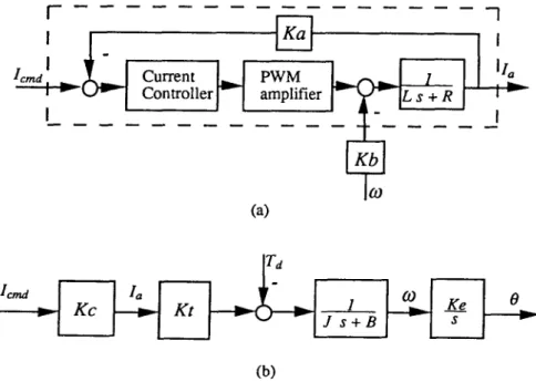
A block diagram of a D C servo m o t o r was tested to verify the proposed UIO. Because the bandwidth of the current loop is in general much higher then that of the motor, we can view the current control loop as an ideal gain in practice. In the present U I O implementation, the current loop of the torque-controlled D C servo motor, as shown in Fig. 2(a), was further simplified to a constant Kc as shown in Fig. 2(b). The dynamic equation for a torque-controlled D C servo m o t o r is
[
On.oat P w M Controller i v [ amplifierI
(a) ] Icmd J s + B(b)
226 Shao-Kun9 Chan 9 et al. TABLE I
Parameters of the Sanyo U718 T D C servo motor
Component Symbol Unit
DC servo motor R 3. lf~ K~ 0.21952 N" m/A J 2.1756×10 4Kg'm2 B 5.333 x 10 -4 N . m / ( r a d - s -I) Kb 0.21952 N/(rad" s -~) Static friction 0.0539 N" m
Tacho gain Hg 0.66845 V/(rad" s-t)
Current feedback gain K. 0.2 V/Amp
Encoder gain K~ 636.62 pulse/rad
D/A gain Kd 2.442 X 10 - 3 V/pulse
Pitch of lead screw Kz 5 mm/rev
B
K,
1) Td (t)
~ ( t ) = -- - ) ~ o ( t ) + 7 - L ( t ) - d(t) = Ko~o(t).
where K,, J, B and Kb are the torque constant, inertia, viscous friction coefficient and back e.m.f, of the motor, respectively; Ke is the gain of the encoder, 0 and 0 are the angular position and velocity of the m o t o r in the units of pulse and pulse/s, respectively. With the parameters o f the D C servo m o t o r listed in Table I, the m o t o r in state- space f o r m is
I
- 2 . 4 5 1 4 2 ~ ( t ) = 4596.433 y(t) = I 4 5 9 ~ "433 0 I x ( t ) + [-0.21952q [--- 17L
0 lug's+L0/ '
0 l x ( t ) 636.620where x - - [Jt~o O/Ke] T, u = I a , d = Td. With 2 ms sampling time, a stabilized U I O was constructed to estimate the states and disturbance of the servo table system using only the m e a s u r e m e n t of output position and the input a r m a t u r e current. T h a t is, the output equation considered was as follows:
Yk = [0 636.620]xk.
By selecting i as 0.5 for the intermediate sampling o f the stabilized U I O , we obtained the following equation for the auxiliary output:
zk = [2922.598 6 3 6 . 6 2 ] x k + 0 . 3 2 0 9 u , - 1.46189d~. By selecting poles at --0.3 + 0. l j, the stabilized U I O was as follows:
General Structured Observers for Linear Systems 227 [ - 2 . 9 9 3 6 0.7916-] I-0.0014]
[-0.0026],,
Xk+l = --9.1780 2.3936J 2k + L0.0063y k - L o . o o 8 6 p
dk = - 0.6840z~ + [1999.2 0.4355]~k + 0.2195uk.
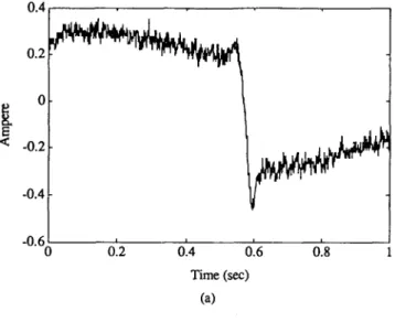
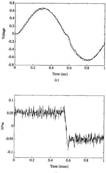
A conventional P controller was used for the position feedback loop. For a sinusoidal command, the measured data for armature current, position and velocity are as plotted in Fig. 3(a)-(c), respectively. The estimated states of the position and velocity, also as shown in Fig. 3(b) and (c), respectively, are in good agreement with the measured data.
2000 0.4 0.2 < -0.2 -0.4 -0"60 012 0'.4 0'.6 0'.8 Time (sec) (a) 1500
8
1000 500 0 0 0.2 0.4 0.6 0.8 Time (see) (b)228
Shao-Kun9 Chan9
et al. 0.8 0.6 0.4 0.2 "~ 0 ;> -0.2 -0.4 -0.6 -0.8 00'.2
0'.4
0'.6
0'.8
Time (sec) (c) Z 0 " -0.05 -0.1 0 012014
0.6 0.8 1 Time (msec) (d)FIG. 3. Results of the stabilized UIO for the servo motor (a) measured current; (b) measured (dotted) and estimated (solid) position; (c) measured (dotted) and estimated (solid) velocity;
and (d) estimated Coulomb friction torque.
W h e n a servo m o t o r operates w i t h o u t a n y external load, the m a j o r disturbance is the C o u l o m b friction only, since the viscous friction has already been considered in the U I O design. Indeed, the estimated disturbance s h o w n in Fig. 3(d) exhibits the exact characteristics o f C o u l o m b friction, which is c o n s t a n t a n d changes in sign as the direction o f m o t i o n changes. C o m p a r e d with the value o f 0.0539 N - m for the static friction t o r q u e p r o v i d e d by the m a n u f a c t u r e r (as in Table I), the present estimation results which range a r o u n d 0.05 N" m are quite satisfactory.
W
General Structured Observers for Linear Systems
Force
. , ~ - -Distance
~
Force
[ dynam°meterl
~I
Positioning Table
[
7 M oto
FIG. 4. Experimental setup for the servo table system.
229 Charge Amplifier I Low Pass I Filter
A/D
5.2. External force monitoring for the servo table
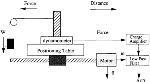
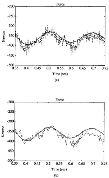
We next provided an external sinusoidal load to the servo table system shown in Fig. 4. All the external loading, inertia o f the table and the ball screw, and machine slide friction can be categorized as disturbances to the servo motor. When the tare current, which was measured without loading, is subtracted, the external force estimated by multiplying the measured armature current by the torque constant is in good agreement with the force as measured by a dynamometer, as shown in Fig. 5(a). Moreover, the estimated force from the stabilized UIO, as shown in Fig. 5(b), is also in good agreement with the measured force. As can be seen from the figures, the stabilized UIO renders satisfactory estimations for position, velocity and external load even without the mea- sured velocity data.
VI. Conclusion
This paper has considered the UIO problem from the perspective o f the general structured observer, which leads to a more concise and straightforward formulation of the problem. The set of all unknown input decoupling GS observers has been derived by computing the M o o r e - P e n r o s e generalized inverse. Based on the derived UIO, we formulate a criterion for designing a well-conditioned UIO. By extending the resulting U10, we have developed an extended UIO which can be used to simultaneously estimate both the system states and the unknown inputs for uncertain systems. Equivalence between the UIO and the left inverse system has been proven and general forms for the implementation of an input estimator have also been provided. Moreover, the use of a two-delay output stabilized method means that a stable UIO can always be found without extra sensors. Experimental results concerning a DC servo m o t o r and a servo table system have proven the feasibility and effectiveness o f the proposed UIO designs.
230
Z -200 -250 -300
Shao-Kung Chang et al. Force -350 -400 -450 -500 ;,L J, I; [' " 0.35 0.4 0.45 0.5 0.55 0.6 0.65 0.7 0.75 Time (sec) (a) -200 -250 Force -300 -350 Z -400 -450 -500 0.35 1,* i t~"LL II \11 ~ ~ ~ ~ ~,,~ ~ ' ~ ' U ,i~" '"r ~ 0.4 0.45 0.5 0.55 0.6 0.65 ' 0.7 0.75 Time (sec) (b)
FIG. 5. Results for the servo table (a) the measured (solid) and the armature current calculated (dotted) force; and (b) the measured (solid) and the stabilized-UIO estimated (dotted) force.
References
(1) C. D. Johnson, " O n observers for systems with unknown and inaccessible inputs", Int. J.
Control, Vol. 21, p. 825, 1975.
(2) P. Kudva, N. Viswannadham and A. Ramakrishna, "Observers for linear systems with
unknown inputs", IEEE Trans. Autom. Control, Vol. 25, p. 113, 1980.
(3) F. W. Fairman and R. Hirschorn, "Disturbance decoupled observers having unrestricted
General S t r u c t u r e d Observers f o r Linear S y s t e m s 231
(4) Y. Guan and M. Saif, "A novel approach to the design of unknown input observers", IEEE Trans. Autom. Control, Vol. 36, p. 632, 1991.
(5) M. Hou and P. C. Mtiller, "Design of observers for linear systems with unknown inputs", IEEE Trans. Autom. Control, Vol. 37, p. 871, 1992.
(6) V. L. Syrmos, "Computational observer design techniques for linear systems with unknown inouts using the concept of transmission zeros", IEEE Trans. Autom. Control, Vol. 38, p. 790, 1993.
(7) F. Yang and R. W. Wilde, "Observers for linear systems with unknown inputs", IEEE Trans. Autom. Control, Vol. 33, p. 677, 1988.
(8) J. E. Kurek, "The statevector reconstruction for linear systems with unknown inputs", IEEE Trans. Autom. Control, Vol. 28, p. 1120, 1983.
(9) M. Darouach, M. Zasadzinski and S. J. Xu, "Full-order observers for linear systems with unknown inputs", IEEE Trans. Autom. Control, Vol. 39, p. 606, 1994.
(10) K. Watanabe and D. M. Himmelblau, "Instrument fault detection in systems with uncer- tainties", Int. J. System Sci., Vol. 13, p. 137, 1982.
(11) N. Viswanadham and R Srichander, " F a u l t detection using unknown input observers", Control Theory Adv. Technol., Vol. 3, p. 91, 1987.
(12) P. M. Frank, " F a u l t diagnosis in dynamic systems using analytical and knowledge-based r e d u n d a n c y - - A survey and some new results", Automatica, Vol. 26, p. 459, 1990. (13) M. Saif and Y. Guan, " A new approach to robust fault detection and identification", 1EEE
Trans. Aerospace Electronic Systems, Vol. 29, p. 685, 1993.
(14) K. C. Cheok, N. K. Loh and R. R. Beck, "General structured observers for discrete time linear systems", IEEE Proc. American Control Conf., Vol. 2, p. 614, 1982.
(15) Y. Kaku, H. Mikami and T. Mita, "Design of stabilized digital inverse systems", Systems Control Lett., Vol. 11, p. 123, 1988.
(16) S. K. Chang, W. T. You and P. L. Hsu, "General-structured unknown input observers", IEEE Proc. 1994 American Control Conf., Vol. 2, p. 666, 1994.
(17) E. J. Davison and S. H. Wang, "Properties and calculation of transmission zeros of linear multivariable systems", Automatica, Vol. 10, p. 643, 1974.
(18) S. K. Chang and P. L. Hsu, " A novel design for unknown input fault detection observer", Control Theory Adv. Technol., Vol. 10, p. 1029, 1995.
(19) S. P. Burrows and R. J. Patton, "Design of low-sensitivity modalized observers using left eigenstructure assignment", A I A A J. Guidance, Control and Dynamics, Vol. 15, p. 779, 1991.
(20) J. Kautsky, N. K. Nichols and P. Van Dooren, "Robust pole-assignment in linear state feedback", Int. J. Control, Vol. 41, p. 1129, 1985.
(21) L. C. Shen, S. K. Chang and P. L. Hsu, "Robust fault detection and isolation with unstructured uncertainty using eigenstructure assignment", I E E E Proc. A I A A Guidance, Navoation and Control Conf., Part 3, p. 1861, 1995.
(22) M. K. Sain and J. L. Massey, "Invertiability of linear time-invariant dynamic system", 1EEE Trans. Autom. Control, Vol. 14, p. 141, 1969.
(23) T. Yoshikawa and T. Sugie, "Filtered inverse systems", Int, J. Control, Vol. 43, p. 1661, 1986.
(24) D. Gleason and D. Andrisani, "Observer design for discrete systems with unknown exogen- ous inputs", IEEE Trans. Autom. Control, Vol. 35, p. 932, 1990.
(25) T. Mita and Y. Chida, "2-delay digital robust control--avoiding the problem on unstable zeros", 1EEE Proc. the 27th Conf. on Decision and Control, p. 1883, 1988.
(26) V. Lovass-Nagy, R. J. Miller and D. L. Powers, " A n introduction to the application of the simplest matrix-generalized inverse in system science", IEEE Trans. Circuits and Systems, Vol. 25, p. 766, 1978.
232
Shao-Kun 9 Chan 9
et al.Appendix: The proof of Lemma 2
Proof'.
That the triple (C, A, E) has no unstable transmission zeros implies that for all 2 ~ C1It can readily be shown that this condition is invariant under coordinate transformation. It is shown by Fairman and Hirschorn (3) that if rank(CE) = rank(E), then it is always possible to transform the coordinates so that the matrices C, E are transformed into the form
where E~ e N m×r has full column rank. Then, taking the co-ordinate transformation in the form of Eq. (A1) leads to
.~_[PE, A,1 PF, A,2]
- - L
Azl
A2z
lwhere
A "/A21 A22J
ff E~ '= Ira-El El +.
One can find/~E, "E~ = 0. In fact, PF, is the orthogonal projector whose range is E{ and whose null space is El (26). We thus have
0 rank(I2I"cA 0E])=rank([ 2I"-AC 0E])[(CE) I+CA
1,1)
=rank([ 21"-A+E(CE)+CA
0E])=rank(I2I"c ~ 0E~.+m)×~.+,,)= rank
I 21m--PE~All
- - A 2 11.,
6_s,
•In m - - A 2 2 =rank([Si $2S3]).
0 _6_$2 AS3Obviously, the columns of S~ and $3 are independent. Since El is the null space of/~E,, the columns of E1 and/~E~ A~2 are independent and therefore the columns of $2 and $3 are independent. We thus conclude that for all 2 e Ci
rank(I21ncA 0 E ] ) = n + r iff rank([ 21n-'~C 0E~) = n + r
iff
rank([S1S2S3]) = n+r
iff rank([SlS2]) = n
iff rank([2I'c - A ] ) = n. (A2) Equation (A2) implies that the pair (C,A) is detectable (by PBH rank tests). •