The Handoff Design for Hierarchical Mobile MPLS Networks Based
on M/M/m Queuing Model
Ling-Feng Chiang
(1), Chun-Chieh Wang
(2), Kung-Min Hsieh
(2), and Jiang-Whai Dai
(3)(1) Ph.D student at Electric Engineering Department, Da-Yeh University
(2) Master students at Communication engineering Department, Da-Yeh University
(3) Associate Professor at Electric Engineering Department, Da-Yeh University
Contact E-mail: [email protected]
Abstract
Within the MPLS network, packets with same FEC can easily be identified by their attached label value. The cross-layer topology associates with access protocol and mobile IP mobility agents. In this paper, we reduce the necessarily of agent discovery and thereby proposed an approach to enhance handoff efficiency. This efficient handoff scheme is performed by a foreign tracking agent (FTA) which plays a role as an administrator of a hierarchy which consisted of some foreign agents (FAs) to localize the routing operation of forwarded packets. To analyze the performance of a hierarchical mobile MPLS network, we model the system as a M/M/m system, where m presents the total number of FTA’s parallel processing servers. The mean delay time of the FTA to process the forwarding packets is analyzed through M/M/m queueing model. The minimum number of FTA’s parallel processing servers is derived to provide the possibly guaranteed performance in the network by minimizing the mean delay time.
Keywords: hierarchical Mobile MPLS, M/M/m Queuing, Foreign Tracking Agent, Handoff
摘要
在 MPLS 網路中,具有相同 FEC 的信文是以所 附加的標籤來加以辨識的。對層次架構的網路拓樸 而言必須具有相對的接取協定以及行動 IP 代理 器。在這一篇文章中,我們提出藉由外地追蹤代理 器的方法來減少需要發現代理器的次數已增強交 替效率。而外地追蹤代理器則是扮演著管理由某些 代理器所組成的層次架構之管理員身分,以能夠尋 找適當的方式來轉送信文。在分析層次架構行動 MPLS 網路,我們採用 M/M/m 佇列模型來加以分 析。同時我們也找出在每一個 FTA 中,為了使得平 均延遲時間具有最小值時,每一個 FTA 內部所需的 伺服器數目 m 値。關鍵詞: hierarchical Mobile MPLS, M/M/m Queuing, Foreign Tracking Agent, Handoff
1. Introduction
Mobile IP allows forwarding the internet traffic to a mobile host (MH) even the MH moves from one network to another. To achieve it, a permanent home address on its home network is needed. A care-of
address is used to identify the current location of the MH and to maintain the communication connection with its home agent (HA) (one of two mobility agents) through other network than its home network. The permanent address of the MH is given by a HA. When MH moves to a different network, it has to acquire a care-of address from the new foreign agent (FA) first. Then, MH registers its new care-of address with its HA. HA will associate a permanent address with MH’s updated care-of address to keep up with the whereabouts of the MH. After the associate between permanent address and care-of address of a MH, traffic from other networks can be forwarded by the HA using tunneling mechanism to the FA that the mobile host visited. Then, FA detunnels the forwarded packet and deliveries the packet to the MH according to the care-of address without changing the mobile host’s IP address. For a MH, a care-of address is a temporary IP address and may be an assigned IP from Dynamic Host Configuration Protocol (DHCP) or a static IP address of a foreign agent on a visited network.
Since a packet is traversed through several hops in the network to reach its destination, it encounters both delay and delay jitter depending on accumulating packets in the queue of hop and on the time to examine the destination address in hop’s table lookup. These potential issues can be much reduced by an efficient label switching operation. To maintain the label bindings, label distribution protocol (LDP) is used and label distribution information is needed to be reliably transmitted between nodes in an MPLS network. MPLS [5-8] provides flexible services, simplifies network architecture and allows the network to enable sophisticated load balancing.
In MPLS mechanism, forwarding equivalent class (FEC) of labeled packet provides differential services over high-speed networks. Label value is attached to the arriving classes depending on the FEC and identifies the output port for the next hop. In other words, FEC is used to describe an association of packets with a destination address and indicates the class of traffic. To reduce the redundant routings, FEC allows the grouping of packets into classes and provides an efficient quality of service (QoS) operation. Different FECs and their associated labels are used for different classes of services. To reduce the handoff latency, [11] proposed a hierarchical mobile
MPLS by introducing a foreign domain agent. In [11], FA forwards the registration message to the foreign domain agent instead of the HA of the MH. According to their simulation results, the end-to-end delay and handoff latency is still long for the delay sensitive applications. To improve these disadvantages, [12] proposed an adaptive hierarchical mobile MPLS scheme. In [2], this scheme is also based on the concept of foreign domain agent. Therefore, the handoff latency are not obviously enhanced. In fact, hierarchical mobile IP protocol adopt a hierarchical of FAs to localize the registration traffic [10] Therefore, a dynamic hierarchical mobile MPLS with a foreign tracking agent (FTA) is proposed here based on the concept of MPLS technology. However, how quantity of processing servers in each FTA should be implemented must be studied to get higher efficiency.
The rest of this paper is organized as follows; in Section 2, we describe the system operation of FTA hierarchy structure based on the concept of the MPLS network. In Section 3, the mean waiting time from our established M/M/m queuing is derived; follows by deriving the optimal number of FAs in a FTA. Section 4 presents the numerical results and the concluding remarks are discussed in Section 5.
2. Wireless MPLS system with a FTA
The one objective of a cross-layer design is to enhance the mobility management when MH changes its mobility agent and register. To obtain better performance, FTA is proposed here and is responsible for layer 2 mobility of MH. But it executes layer 3 protocol if it wants to take over the routing and handoff. All corresponding label message are also exchanged among neighbor’s FTA by the authentication and verification processes. Notice that the release requires and release replies are exchanged only between the FTA and the previous FA. And the transmitted packets are forwarded crossings relative FTA through the new FA. Under mobile MPLS network, FA just knows the labels from its adjacent FAs. But FTA must obtain all labels from FAs which are in its coverage.
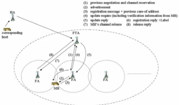
In our scheme, FTA is able to send packets directly to the new FA without the services of immediate FAs, see Figure 1, and does not support the function of paging the MH [1]. This operation gives a smooth handoff mechanism when a MH moves away from one foreign network to another and is described as follows.
Step 1 - The pre-reservation channel is negotiated between FTA and a FA before handoff using tracking scheme.
Step 2 - When a MH moves to the new FA which it visited, it must get the care-of address of the new visited FA.
Step 3 - When the MH wants to register with the new
visited FA, it has to send a registration require.
Step 4 - After receiving the registration request, the new visited FA sends an update request to the FTA.
Step 5 - FTA returns an update reply to the new which is visited by the MH after it received the update request.
Step 6 - The new visited FA sends a registration reply to the MH with a label and a pre-reservation channel.
Step 7 - FTA sends a release request to the previous FA.
Step 8 - After receiving the release request, the previous FA returns a release reply to the FTA. Then, the handoff procedure is completed.
Figure 1: The FTA system
This scheme will not cause longer handoff latency and channel contention time. It also provides multiple real-time services while also achieving high quality of service support. In our system, we assume that there are enough resources to satisfy the QoS requirement of MH during handoff procedure.
3. The minimum number of FAs within a
FTA
In this section, dynamic hierarchical network with a foreign tracking agent (FTA) based on the concept of MPLS technology is proposed. If the numbers of processing servers in a FTA are too much, the resources within these processing servers are wasted. Otherwise, the performance efficiency will be rapidly decayed if the numbers of processing servers in a FTA are too small. Therefore, to quantize optimal processing servers in a FTA for the better performance is needed. Under the assumption that the mutual arrival and departure time between arbitrary packets are exponential distribution, we adopt the M/M/m
queueing model [3, 4, 9] to analyze the performance of FTA forwarding scheme, see Figure 2.
In the system, we assume that the arrival rates of classes are the same with each other, meaning that
λ
We also assume that the service rate of each processing server is same with the others, whereby
{
μ μ}
μk =min k ,m ,k=1,2,L (2) Denote = <1 μ λ ρ mto be the server utilization.
According to the Markov chain which is depicted in Figure 3, the steady state probability [4] is
Figure 2: Function diagram of a FTA
( )
( )
⎪ ⎪ ⎩ ⎪ ⎪ ⎨ ⎧ ≥ ⎟⎟ ⎠ ⎞ ⎜⎜ ⎝ ⎛ = + ≤ ⎟⎟ ⎠ ⎞ ⎜⎜ ⎝ ⎛ = + = − − = − = − =∏
∏
∏
m k if m m m i m k if k i m k k m i k m j k k i k , ! 1 1 , ! 1 0 1 0 1 0 0 1 0 0 μ λ π μ λ μ λ π μ λ π μ λ π π (3) and( )
( )
1 1 0 0 1 1 ! ! − − = ⎥⎦ ⎤ ⎢ ⎣ ⎡ − + =∑
ρ ρ ρ π m m k m m m k k (4)The queueing length LD is given as
∑
∑
= ∞ + = + = m k km m k k D m m k k m L 1 1 0 0 ! ! ) ( ρ π ρ π (5)According to Little’s law, the mean waiting time under the condition of m is
λD
L
W= (6)
and the mean delay time to forward the arrival packet under the condition of m is
μ λ μ 1 1 + = + = D f L W D (7)
Fig. 3: Markov chain of M/M/m
Let tHA→FTA be the spent time that the
corresponding host transmits a packet to FTA in which the MH is through the MH’s HA. Denote tFTA→MH to
be the transmission time that a forwarding packet is forwarded to the MH through the FA in which the MH visited. Therefore, the total mean delay to transmitted a packet from the corresponding host to a specific MH is given as MH FTA FTA HA f t t D D= + → + → (8)
Let d1 be the separated distance between FTA and FA; d2 be the separated distance between the visited FA and MH. Assume
τ
to be the processing time of the visited FA for forwarding the packet to the MH. Then τ + + = → c d d tFTA MH 2 1 (9)From Equation (5) to Equation (7), it is realized that the mean waiting time of classes is reduced when
m increases. However, a minimum value of m
should be given to maintain the minimum mean delay time or mean waiting time. Therefore, the minimum amount of FAs to process the arriving classes in this section will be discussed. Given a fixed m , mean delay time will be minimized if mean waiting time is minimized. To obtain the minimum mean waiting time, we set 0 ≡ = λ dm dL dm dW D
After some mathematical operations, we obtain
(
1 2 3)
0 0 ' 0 + − + + = = g h h h dm dLD π π (10) where ⎥ ⎥ ⎥ ⎥ ⎦ ⎤ ⎢ ⎢ ⎢ ⎢ ⎣ ⎡ − ⎟ ⎠ ⎞ ⎜ ⎝ ⎛ + − ⎟ ⎠ ⎞ ⎜ ⎝ ⎛ + − = + ∞ =∑
2 0 1 0 2 0 0 0 0 0 0 ) ( ! ! 0 ρ ρ ρ ρ ρ ρ ρ ρ ρ m m m m m m m m k e g m m m k k (11)∑
∞ = + ⎪⎭ ⎪ ⎬ ⎫ ⎪⎩ ⎪ ⎨ ⎧ + + − + = 0 0 0 1 ] )! [( )! ( 1 ln )! ( k k m k m dm d k m k m h ρ ρ ρ (12)∑
+ = + = + m h i i h m h m dm d 1 1 )! ( ] )! [( (13) ⎥ ⎦ ⎤ ⎢ ⎣ ⎡ − + ⎥ ⎥ ⎥ ⎥ ⎥ ⎦ ⎤ ⎢ ⎢ ⎢ ⎢ ⎢ ⎣ ⎡ − ⎟ ⎠ ⎞ ⎜ ⎝ ⎛ + − ⎟ ⎠ ⎞ ⎜ ⎝ ⎛ = + ) ! ( ) ! ( ) ln 1 ( ! ) ( 2 2 0 1 0 2 0 0 0 2 m dm d m m m m m m x m m m m h m m m ρ ρ ρ ρ ρ (14) ⎪ ⎪ ⎪ ⎪ ⎭ ⎪⎪ ⎪ ⎪ ⎬ ⎫ ⎪ ⎪ ⎪ ⎪ ⎩ ⎪⎪ ⎪ ⎪ ⎨ ⎧ ⎥ ⎥ ⎥ ⎥ ⎦ ⎤ ⎢ ⎢ ⎢ ⎢ ⎣ ⎡ − − − − − ⎟ ⎠ ⎞ ⎜ ⎝ ⎛ ⎟ ⎠ ⎞ ⎜ ⎝ ⎛ + − ⎟ ⎠ ⎞ ⎜ ⎝ ⎛ − ⎟ ⎠ ⎞ ⎜ ⎝ ⎛ − ⎟ ⎠ ⎞ ⎜ ⎝ ⎛ − = − 3 0 2 0 0 2 0 1 0 2 0 0 0 0 0 0 0 0 3 ) ( 2 ) ( 1 ln ) ( 1 ln ! ρ ρ ρ ρ ρ ρ ρ ρ ρ ρ ρ ρ ρ m m m m m m m m m m m m m m h m m m m (15) and μ λ ρρ0 = m = is known as the system utilization. According the results from Appendix A, we have
f 2 0 ' 0 π π = (16) Where f is defined in Equation (A.8). Finally, the optimal value of
m
can be derived according to the following equation;(
1 2 3)
0 0 2 0fg+π
−h+h +h =π
(17)4. Numerical results
In MPLS network, packets with the same FEC can easily be identified from their attached label value. To achieve sufficient capacity planning for QoS routing and faster packet forwarding performance, the establishment of simultaneous processing servers is required. In this section, M/M/m model is employed to evaluate the optimal performance of FTA in the hierarchy mobile MPLS network. To achieve this, we have to obtain the optimal number of processing servers. For this system, to minimize mean delay time, the relationship between the number of processing servers m and system utilization ρ0 must be evaluated as illustrated in Equation (17). To depict the detailed boundary of m for a variety of system utilization, the system utilization is initially increased from 0 to 0.9. As depicted in Figure 4, the value of m increases with the increment of ρ . 0 However, it maintains at the same level within a fixed range. This phenomenon is incurred due to the processing capability of the LSR in the MPLS network that provides insufficient delay requirement if the arriving loads excess some constrains.
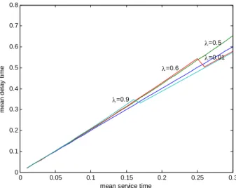
Figure 5 demonstrated that increasing the number of parallel processing servers can reduce the mean waiting time. However, changes in the mean waiting time are not obvious when the mean service time,1/μ, is less than 0.13 seconds. In addition, mean delay time is reduced when the optimal mechanism is used (the curves at λ=0.6 and λ=0.9). In Figure 5, it also illustrates that the mean delay time on the condition of
9 . 0 =
λ is better enhanced than that of λ=0.6 if optimal mechanism is performed due to the requirement of more parallel processing servers.
5. Conclusion
In this paper, the relationship between the optimal number of a FTA’s parallel processing servers and the different system loads is presented. In addition, the presented methodology can be applied to minimize the mean delay time according to the processing ability of the FTA for different system load. When the handoff is executed, the service rate is slow. However, the service rate is fast only on forwarding the transmission packet after the handoff is achieved. The analyzed results are computationally efficient and it allows us to achieve the requested QoS requirements, with a properly selection of reasonable numbers of parallel processing servers.
0 0.1 0.2 0.3 0.4 0.5 0.6 0.7 0.8 0.9 0 0.5 1 1.5 2 2.5 3 3.5 4 op ti m a l n u m b e r of pro c es s ing s e rv e rs m ρ0
Figure 4: The relationship between optimal number of processing servers and ρ 0
0 0.05 0.1 0.15 0.2 0.25 0.3 0 0.1 0.2 0.3 0.4 0.5 0.6 0.7 0.8
mean service time
m e an d e la y t im e λ=0.9 λ=0.6 λ=0.5 λ=0.01
Figure 5: The mean delay time of FTA, Df, under optimal condition.
Appendix A: The result of
dm dLD
From the following equation
[
]
⎪⎭ ⎪ ⎬ ⎫ ⎪⎩ ⎪ ⎨ ⎧ ⎥ ⎦ ⎤ ⎢ ⎣ ⎡ − + − + ⎥ ⎦ ⎤ ⎢ ⎣ ⎡ − = ⎪⎭ ⎪ ⎬ ⎫ ⎪⎩ ⎪ ⎨ ⎧ + + + + + + ⎥ ⎦ ⎤ ⎢ ⎣ ⎡ − = ⎭ ⎬ ⎫ ⎩ ⎨ ⎧ + = ⎥ ⎦ ⎤ ⎢ ⎣ ⎡ + = + + ∞ = + + ∞ = ∞ = − = ∞ + = = ∞ + =∑
∑
∑
∑
∑
∑
∑
2 1 1 0 0 1 1 0 0 0 1 0 1 0 0 1 1 0 0 ) 1 ( 1 1 ! ! ) ( ) 2 1 ( ) 1 ( ! ! ) ( ! ) ( ! )! ( ) ( ) ( ! ! ) ( ρ ρ ρ ρ π ρ ρπ ρ ρ ρ ρ π ρ ρ ρπ ρ π ρ ρ π ρ π ρ π ρ m m m m k k m m m m k km k k m k km k m k m k km m k k D m m m k m e m dm d m m m k m k m m dm d k m m k m m dm d m m k k m k dm d dm dL L L (A.1) we have( ) ( ) ( ) ( ) ⎪ ⎪ ⎭ ⎪ ⎪ ⎬ ⎫ ⎥ ⎥ ⎥ ⎥ ⎥ ⎦ ⎤ ⎢ ⎢ ⎢ ⎢ ⎢ ⎣ ⎡ − ⎟ ⎠ ⎞ ⎜ ⎝ ⎛ + ⎟⎟ ⎠ ⎞ ⎜⎜ ⎝ ⎛ − ⎟ ⎠ ⎞ ⎜ ⎝ ⎛ + ⎟ ⎠ ⎞ ⎜ ⎝ ⎛ − ⎪ ⎪ ⎩ ⎪ ⎪ ⎨ ⎧ + ⎟⎟ ⎠ ⎞ ⎜⎜ ⎝ ⎛ ⎥ ⎥ ⎥ ⎥ ⎥ ⎦ ⎤ ⎢ ⎢ ⎢ ⎢ ⎢ ⎣ ⎡ − ⎟ ⎠ ⎞ ⎜ ⎝ ⎛ + − ⎟ ⎠ ⎞ ⎜ ⎝ ⎛ + ⎥ ⎥ ⎦ ⎤ ⎢ ⎢ ⎣ ⎡ − + ⎪ ⎪ ⎭ ⎪ ⎪ ⎬ ⎫ ⎪ ⎪ ⎩ ⎪ ⎪ ⎨ ⎧ ⎥ ⎥ ⎥ ⎥ ⎥ ⎦ ⎤ ⎢ ⎢ ⎢ ⎢ ⎢ ⎣ ⎡ − ⎟ ⎠ ⎞ ⎜ ⎝ ⎛ + − ⎟ ⎠ ⎞ ⎜ ⎝ ⎛ + − = ⎪ ⎪ ⎪ ⎪ ⎭ ⎪⎪ ⎪ ⎪ ⎬ ⎫ ⎪ ⎪ ⎪ ⎪ ⎩ ⎪⎪ ⎪ ⎪ ⎨ ⎧ ⎥ ⎥ ⎥ ⎥ ⎥ ⎦ ⎤ ⎢ ⎢ ⎢ ⎢ ⎢ ⎣ ⎡ − ⎟ ⎠ ⎞ ⎜ ⎝ ⎛ + − ⎟ ⎠ ⎞ ⎜ ⎝ ⎛ + − = + + ∞ = ∞ = + + ∞ =
∑
∑
∑
2 0 1 0 2 0 0 0 0 0 0 2 0 1 0 2 0 0 0 0 0 0 2 0 1 0 2 0 0 0 0 0 0 ' 0 2 0 1 0 2 0 0 0 0 0 0 0 0 0 ! ! ! ) ( ! ! ) ( ! ) ( ! ) ( ) ( 0 0 ρ ρ ρ ρ ρ ρ ρ ρ ρ ρ ρ ρ ρ ρ ρ π ρ ρ ρ ρ ρ ρ ρ ρ π ρ ρ ρ ρ ρ π ρ π ρ π ρ ρ ρ m m m dm d m m dm d m m dm d m m m m m m dm d m m m m m m k dm d m m m m m m m m m k e m m m m m m m m m m k m m e dm d dm dL m m m m m m m m k k m k m m m k m m m m k k D (A.2) To calculate ⎥ ⎦ ⎤ ⎢ ⎣ ⎡∑
∞ =m k k k dm d ! 0 ρ , m m dm d ⎟ ⎠ ⎞ ⎜ ⎝ ⎛ρ0 , 02 1 0 2 ) ( ρ ρ − ⎟ ⎠ ⎞ ⎜ ⎝ ⎛ + m m m dm d m , and m! dmd , we obtain the following equations,
respectively. ⎥ ⎦ ⎤ ⎢ ⎣ ⎡ + + − + = ⎥ ⎥ ⎥ ⎥ ⎦ ⎤ ⎢ ⎢ ⎢ ⎢ ⎣ ⎡ + + − + = + + − + = ⎟⎟ ⎠ ⎞ ⎜⎜ ⎝ ⎛ + = ⎥ ⎦ ⎤ ⎢ ⎣ ⎡ + = ⎥ ⎦ ⎤ ⎢ ⎣ ⎡
∑
∑
∑
∑
∑
∑
∞ = + ∞ = ∞ = ∞ = ∞ = + ∞ = ] )! [( )! ( 1 ln )! ( ] )! [( ] )! [( )! ( ln ] )! [( ] )! [( )! ( )! ( )! ( ! 0 0 0 2 0 0 0 0 2 0 0 0 0 0 0 0 0 0 k m dm d k m k m k m k m dm d k m k m k m dm d dm d k m k m dm d k m dm d k dm d k k m k m m k k m m k k m k k k m m k k ρ ρ ρ ρ ρ ρ ρ ρ ρ ρ ρ ρ ρ (A.3)( )
⎟ ⎠ ⎞ ⎜ ⎝ ⎛ − ⎟ ⎠ ⎞ ⎜ ⎝ ⎛ = + ⎟ ⎠ ⎞ ⎜ ⎝ ⎛ − ⎟ ⎠ ⎞ ⎜ ⎝ ⎛ = − ⎟ ⎠ ⎞ ⎜ ⎝ ⎛ = − = − = ⎟ ⎠ ⎞ ⎜ ⎝ ⎛ 1 ln ) ln 1 ( ln ) ln ( ln ) ( ln ) ( ) ( ln 0 0 0 0 0 ln 2 0 0 0 2 ln 0 0 0 2 0 0 0 0 m m m m m m m dm d e m m m e dm d m m m dm d m m dm d m m m m m m m m m m m m m m m m m m m ρ ρ ρ ρ ρ ρ ρ ρ ρ ρ ρ ρ ρ ρ ρ (A.4) ⎪ ⎪ ⎭ ⎪⎪ ⎬ ⎫ ⎪ ⎪ ⎩ ⎪⎪ ⎨ ⎧ − − − − − ⎟ ⎠ ⎞ ⎜ ⎝ ⎛ ⎟ ⎠ ⎞ ⎜ ⎝ ⎛ = ⎪ ⎪ ⎭ ⎪⎪ ⎬ ⎫ ⎪ ⎪ ⎩ ⎪⎪ ⎨ ⎧ − − − − + + = − − − − ⎥ ⎥ ⎥ ⎦ ⎤ ⎢ ⎢ ⎢ ⎣ ⎡ ⎟ ⎠ ⎞ ⎜ ⎝ ⎛− − − + = ⎥ ⎥ ⎦ ⎤ ⎢ ⎢ ⎣ ⎡ − = − ⎟ ⎠ ⎞ ⎜ ⎝ ⎛ − − + − + + − + + − + + − + + 3 0 2 0 0 2 0 1 0 3 0 2 0 0 1 1 0 4 0 0 1 1 0 2 0 1 1 0 0 1 1 0 2 0 1 1 0 2 0 1 0 2 ) ( 2 ) ( 1 ln ) ( 2 ) ( 1 ln ln ) ( ) ( 2 ) ( 1 ln ln ) ( ) ( ρ ρ ρ ρ ρ ρ ρ ρ ρ ρ ρ ρ ρ ρ ρ ρ ρ ρ ρ ρ m m m m m m m m m m m m m m m m m m m m m m m dm d m m m dm d m m m m m m m m m m m m (A.5) f m m m dm d m m m m m m k m k m dm d k m m m m dm d m m m m m m k m dm d m m m k m e dm d k m k m dm d m m k k m m m m k k m m k k m m k m k 2 0 2 2 0 0 0 0 0 0 0 0 0 2 0 2 2 0 0 0 0 0 0 0 0 0 2 0 0 0 0 0 2 0 1 1 0 ' 0 ) ! ( ) ( ) ! ( ) ( ! ) ln 1 ( ! ) ( )! ( ] )! [( ln )! ( ) ! ( ) ( ! ) ( ! ! ) )( ln ( )! ( ! ) ( )! ( 1 1 ! ) ( ! ) ( 0 π ρ ρ ρ ρ ρ ρ ρ ρ π ρ ρ ρ ρ ρ ρ ρ ρ π ρ ρ ρ π ρ ρ ρ π ρ = ⎪ ⎪ ⎪ ⎪ ⎭ ⎪ ⎪ ⎪ ⎪ ⎬ ⎫ ⎪ ⎪ ⎪ ⎪ ⎩ ⎪ ⎪ ⎪ ⎪ ⎨ ⎧ − ⎥⎦ ⎤ ⎢⎣ ⎡ + − + + − − ⎟ ⎟ ⎟ ⎟ ⎠ ⎞ ⎜ ⎜ ⎜ ⎜ ⎝ ⎛ ⎥ ⎥ ⎥ ⎥ ⎦ ⎤ ⎢ ⎢ ⎢ ⎢ ⎣ ⎡ + + − + = ⎪ ⎪ ⎪ ⎭ ⎪⎪ ⎪ ⎬ ⎫ ⎪ ⎪ ⎪ ⎩ ⎪⎪ ⎪ ⎨ ⎧ − ⎥⎦ ⎤ ⎢⎣ ⎡ + − − − + + ⎟ ⎟ ⎠ ⎞ ⎜ ⎜ ⎝ ⎛ + − − = ⎥ ⎦ ⎤ ⎢ ⎣ ⎡ − + + − − = ⎥ ⎦ ⎤ ⎢ ⎣ ⎡ ⎟⎟ ⎠ ⎞ ⎜⎜ ⎝ ⎛ − + =∑
∑
∑
∑
∞ = + ∞ = + ∞ = + − − = (A.6) In additional,[
]
∑
= − = = ⎟⎟ ⎠ ⎞ ⎜⎜ ⎝ ⎛ + + − + − + − + = + + − + − + − + = − − − − = m i m a i m m m m m m m m m m m m m m m a m m m m m dm d m dm d 1 1 1 ! 1 ) 3 ( 1 ) 2 ( 1 ) 1 ( 1 1 ! 1 ! ) 3 ( ! ) 2 ( ! ) 1 ( ! ! ) ( ) 3 )( 2 )( 1 ( ! L L L (A.7) where⎥ ⎥ ⎥ ⎥ ⎦ ⎤ ⎢ ⎢ ⎢ ⎢ ⎣ ⎡ − + − + − + − ⎟ ⎟ ⎟ ⎟ ⎠ ⎞ ⎜ ⎜ ⎜ ⎜ ⎝ ⎛ ⎥ ⎥ ⎥ ⎥ ⎦ ⎤ ⎢ ⎢ ⎢ ⎢ ⎣ ⎡ + + − + =
∑
∞ = + ) ( ! ) ! ( ) ( 1 ! ln 1 ! )! ( ] )! [( ln )! ( 0 2 0 0 0 0 0 0 0 0 ρ ρ ρ ρ ρ ρ ρ ρ m m m dm d m m m m m m k m k m dm d k m f m m k k m (A.8) Reference[1]. Behcet Sarikaya, and Timuchin Ozugur, “Tracking Agent Based Paging for Wireless LANs”, IEEE Consumer Communications and Networking Conference, pp. 279-284, January 2004. CCNC 2004.
[2]. Charless E. Perkins, “Mobile IP”, IEEE
Communications Magazine, pp. 84-99, May
1997.
[3] Donald Gross, and Carl M. Harris,
Fundamentals of Queueing Theorem, 2nd edition, John Wiley&Sons, 1985.
[4] Edward P.C. Kao, An Introduction to Stochastic Processes, Duxbury Press at Wadsworth
Publishing Company, 1997.
[5] E. Rosen, A. Viswanathan, and R. Callon, “Multiprotocol Label Switching Architecture”,
draft-ietf-mpls-diff-ext-01.txt, February 1999.
[6] G. Armitage, “MPLS: The Magic Behind the Myths", IEEE Communications Magazine, pp.
124-131, January 20000.
[7] G.M. Lee, and H.K. Choi, “A Study of Flow-based Traffic Admission Control Algorithm in the ATM-based MPLS Network”, in Proc.
IEEE ICIN’01, pp. 213-218, 2001.
[8] G. Liu, and X. Lin, “MPLS Performance Evaluation in Backbone Network”, in IEEE
International Conference on Communications, pp.
1179-1183, 2002.
[9] Hooi Miin Soo, and Jong-Moon Chung,
“Analysis of Nonpreemptive priority Queueing of MPLS Networks with BULK Arrivals”, The 2002
45th Midwest Symposium on Circuits and Systems, Volume 3, 4-7 Aug. pp. III.81-III.84,
2002.
[10]. H. Zhon, et al., “Dynamic Hierarchical Mobile MPLS for Next Generation All-IP Wireless Network“, IEEE 61st Vehicular Technology Conference, Vol. 4, pp. 2230 – 2234, 30 May-1
June 2005.
[11]. T. Yang, and D. Makrakis, “Hierarchical Mobile MPLS: Supporting Delay Sensitive Applications over Wireless Internet”, 2001 International
Conferences on Info-tech and Info-net, Vol. 2, pp.
453 – 458, 29 Oct.-1 Nov. 2001.
[12]. Xingchuan Yuan; Lishan Kang; Yuping Chen, “An adaptive hierarchical mobile MPLS scheme”, Proceedings. 2005 International Conference on Wireless Communications, Networking and Mobile Computing, Vol. 2, pp.