國 立 交 通 大 學
電信工程學系
碩 士 論 文
從網路吞吐量觀點分析並設計
合作式通訊的媒介存取策略
Analysis and Determination of Cooperative MAC
Strategies from Throughput Perspectives
研究生:廖俊傑
指導教授:方凱田 教授
從網路吞吐量觀點分析並設計合作式通訊的媒介存取策略
Analysis and Determination of Cooperative MAC Strategies
from Throughput Perspectives
研究生:廖俊傑 Student:Chun-Chieh Liao
指導教授:方凱田 Advisor:Kai-Ten Feng
國 立 交 通 大 學
電 信 工 程 學 系
碩 士 論 文
A ThesisSubmitted to Department of Communications Engineering College of Electrical and Computer Engineering
National Chiao Tung University in partial Fulfillment of the Requirements
for the Degree of Master of Science
in
Communications Engineering June 2008
從網路吞吐量觀點分析並設計
合作式通訊的媒介存取策略
學生:廖俊傑
指導教授
:方凱田 教授
國立交通大學電信工程學系碩士班
摘
要
近幾年來,合作式通訊被提出來成為一種新的通訊模式,利用周遭的鄰近節 點來提昇自我的分集增益(Diversity Gain),進而改善點對點之間的通訊品質。 從實體層(Physical Layer)的角度上來評論,合作式通訊能有效地降低接收端 的位元錯誤率,以達到通訊可信度上的提升。然而,在實作複雜度的限制下,半 工傳輸(Half-Duplex)是現今大部分通訊系統的假設,因而,合作式通訊的模 式往往需要兩個階段才能完成,導致在傳輸時間上的延伸變得是無可避免的。因 此,若改由整體網路的吞吐量(Network Throughput)觀點來思考,合作式通訊 不見得會帶來所期待的效能。在本論文中,我們將以 IEEE 802.11 媒介接取控制 技術為基礎,佐以模擬驗證,利用二維的馬可夫鏈(Two Dimensional Markov Chain)的數學分析來探討合作式通訊於網路吞吐量的表現。在媒介接取控制的 考量下,適當地找尋合作式通訊的使用時機。接著,將提出新的通訊協定並整合 傳統點對點通訊系統及合作式通訊技術。以完整通道資訊為基礎之合作式通訊協 定(Full-CSI based Cooperative MAC Protocol)將會依據完整的通道資訊來 決定使用合作式通訊的時機,最適合的節點也會被選取並幫忙資料的傳輸,然 而,通道資訊的交換可能會造成網路吞吐量的下降,因此以位元競爭方式之合作 式通訊協定(Bitwise Competition based Cooperative MAC Protocol)利用競 爭的方式來選擇適合的節點,可以有效的降低控制訊框傳輸的數量,雖然無法獲 得所有的通道資訊,從模擬的結果可以發現以位元競爭方式之合作式通訊協定在 大部分的通道環境下還是有較佳的網路吞吐量表現。
Analysis and Determination of Cooperative MAC
Strategies from Throughput Perspectives
Student : Chun-Chieh Liao Advisor : Kai-Ten Feng
Department of Communications Engineering National Chiao Tung University
Abstract
In recent years, cooperative communication has been developed as a new com-munication strategy that incorporates a relay node to assist the direct point-to-point transmission. However, owing to the longer transmission time resulting from the coop-erative schemes, there is no guarantee to enhance the network throughput in view of the medium access control (MAC) performance. In this thesis, the system throughput of the combined direct/cooperative scheme is evaluated by exploiting the proposed analyt-ical model based on the IEEE 802.11 MAC protocol. In terms of network throughput, whether to adopt the cooperative schemes depends on the tradeoff between the co-operative transmission delay and the channel condition of the direct communication. Two cooperative MAC protocols are proposed to determine the circumstances for ac-tivating the cooperative communication based on the channel conditions. The full-CSI based cooperative (FCC) MAC protocol is introduced to choose the feasible transmis-sion scheme and the relay node according to the full channel information. However, the overhead caused by the FCC scheme may degrade the throughput performance as the number of relays is significantly increased. Therefore, the bitwise competition based cooperative (BCC) MAC protocol is utilized to determine a feasible relay node for data transmission. Simulations are also conducted to further validate the effectiveness of the proposed analytical models and cooperative MAC protocols.
誌
謝
兩年的研究生涯即將邁向終點,兩年的時間過得很快也很充實,首先非常感 謝方凱田老師給予研究上的指導還有許多生活上的鼓勵,也謝謝蘇育德老師以及 黃經堯老師撥空參加口試並提供許多實質的建議。回顧碩一的時期,研究的起頭 總是特別困難,因此要特別感謝裕彬激發許多研究上的想法,更謝謝柏軒、文俊、 建華與仲賢學長們常常解決我對研究上的疑問。也很開心能成為瑞廷、佳仕與佳 偉的同學,除了經常一起討論課業與研究的問題外,天馬行空地對話更令人難 忘。而實驗室的其懋、萬邦、俊宇、承澤和惟能學弟們,謝謝你們為實驗室帶來 許多歡樂。最後非常感謝爸媽與弟弟的關心並謝謝所有幫助過我的朋友。 廖俊傑謹誌 于新竹國立交通大學
Contents
Chinese Abstract i English Abstract ii Acknowledgement iii Contents iv List of Figures vi 1 Introduction 12 Markovian Model with Combined Direct/Cooperative Strategy 6
3 Throughput Analysis for Direct/Cooperative Schemes 11
3.1 FER Calculation for Direct/Cooperative Transmissions . . . 12
3.2 Saturation Throughput Analysis . . . 14
3.3 Throughput Comparison between Direct and Cooperative Communications 19
4 Proposed Cooperative MAC Protocols 25
4.1 Full CSI based Cooperative (FCC) MAC Protocol . . . 29
5 Performance Evaluation 34
List of Figures
2.1 Network scenario with the combined direct/cooperative transmission scheme. 7 2.2 Markov chain model for the backoff mechanism with the combined
di-rect/cooperative strategy. . . 8
3.1 Throughput Performance versus the channel quality of direct link σSD
under various values of Rcg. . . 20
3.2 Throughput performance versus different values of the ratio Rcg (left
plot: worse direct channel quality σSD = 35 dB; right plot: better direct
channel quality σSD = 40 dB). . . 22
3.3 Required average SNR σRD via cooperative communication for achieving
the same throughput as that with direct transmission under specific σSD
and σSR values. . . 24
4.1 The schematic diagrams of both the handshake process and data trans-mission for (a) direct transtrans-mission in non-cooperative group, (b) direct transmission in cooperative group, and (c) cooperative transmission in
cooperative group. . . 26
4.2 The specific process in CSI-acquiring period with FCC protocol. . . 30
5.1 Throughput performance versus the average SNR value of boundary node
σDB using FCC protocol (number of sources = 30). . . 35
5.2 Throughput performance versus the average SNR value of boundary node
σDB using BCC protocol (number of sources = 30). . . 36
5.3 Throughput performance versus the number of relays using FCC protocol
with different number of sources (σDB = 30 dB). . . 37
5.4 Throughput performance versus the number of relays using BCC protocol
with different number of sources (σDB = 30 dB). . . 38
5.5 Throughput comparison versus the number of relays with the direct
transmission and proposed protocols (σDB = 30 dB). . . 39
5.6 Throughput comparison versus the number of users with the direct
trans-mission and proposed protocols (σDB = 30 dB). . . 40
5.7 The average number of retransmissions versus the average SNR value of
boundary node σDB via the direct transmission and proposed protocols. 41
5.8 Throughput performance versus the average SNR value of boundary node
Chapter 1
Introduction
Due to the unreliable environment for wireless communication, different types of trans-mission schemes have been developed to maintain the quality of communication. Multi-input multi-output (MIMO) systems are introduced to achieve high capacity by taking advantages of multipath channels and spatial diversity. However, multi-antenna system equipped within mobile devices may not be easily deployed due to the limitation of its physical size. Recently, techniques for cooperative communications are proposed to effectively enhance the diversity gain and robustness with the broadcast nature of wireless communication. Through the help of relays in the network, the virtual an-tenna array can be formed in order to increase the transmission reliability. In other words, data communication between the source and the destination is captured by the relay, which duplicates the frame and consequently delivers it to the destination. In order to acquire diversity gain, the duplicated frames are received and combined at the destination by exploiting different methods, e.g. the maximum ratio combining (MRC) algorithm. Moreover, the amplify-and-forward (AF) and decode-and-forward (DF) pro-posed in [1] are the two commonly used schemes in cooperative communications. In the AF scheme, the relay simply amplifies and forwards the frames that are acquired
from the source; while the relay forwards the received frames to the destination after decoding them correctly in the DF scheme.
Research work have been conducted to explore the cooperative communications from various aspects. The analysis of the cooperative diversity by adopting different cooperative schemes has been investigated in [2–4]; while [5] develops several coop-erative strategies and calculates the resulting capacity. The work presented in [6–8] also delivers the cooperative schemes from the physical (PHY) layer perspectives. The symbol-error-rate performance analysis and optimum power allocation are provided in [6] and [7] with different modulation type. Variable-rate two-phase collaborative communication scheme is proposed in [8] which also provides the performance analysis of outage probability. Moreover, the performance of cooperative communication can further be improved with the utilization of coding strategy as shown in [9, 10]. With the consideration of fading channels, distributed space-time coding schemes and their associated performance analysis are introduced in [11–13]. Furthermore, cooperative automatic repeat request (ARQ) techniques in [14–16] exploit the cooperative diversity to achieve efficient retransmission; while [17] provides the analysis of frame error rate (FER) under various cooperative ARQ protocols.
However, it is noticeable to observe that most of research focus on the cooperative communications from the viewpoint of information theory and PHY layer design. Al-though the FER can be ameliorated by means of the cooperative diversity, there is no assurance to result in enhanced network throughput due to the tradeoff between the FER and the longer frame transmission time. In general, the cooperative schemes will lead to prolonged frame transmission time no matter the AF-based or the DF-based pro-tocols are applied. With the adoption of half-duplex antennas, two phases are required for the relay-based communication in order to complete a data transmission. In other words, data frame must be delivered from the source to both the destination and the
relay with additional duplicated frame transmitted from the relay to the destination. In order to evaluate the combined system including the conventional direct trans-mission and the cooperative communication in terms of the network throughput, a suitable analytical model from the medium access control (MAC) perspectives should be exploited. The IEEE 802.11 [18] has been considered a well-adopted standard for the wireless LANs. In the IEEE 802.11 MAC protocol, the distributed coordination func-tion (DCF) is utilized as the basic mechanism for channel access. The DCF ensures that each node can acquire a fair opportunity to access the wireless medium according to the carrier sensing multiple access with collision avoidance (CSMA/CA) scheme. A random backoff process is executed in each node for the purpose of decreasing the probability of data collision. Moreover, the request-to-send (RTS)/ clear-to-send (CTS) exchange before the data transmission is employed in order to resolve the potential hidden ter-minal problem. A large amount of existing research [19–21] contribute to establish the analytical models for the IEEE 802.11 MAC protocol. The saturation throughput of the IEEE 802.11 DCF is obtained via a two-dimensional Markov chain model as proposed in [19]. The work presented in [20,21] further consider the channel error conditions into the design of the analytical models.
In this thesis, the backoff model of the IEEE 802.11 MAC extended from [19, 20] is adopted to analyze the saturation throughput of the cooperative technology. Both the cooperative and the direct communications are considered in the design of the proposed analytical model. Simulations are also exploited for validating the effectiveness of the proposed model. It can be observed from the analytical results that the performance of the cooperative communication is affected by various factors, especially the FER and the frame transmission delay. Cooperative schemes in general result in decreased FER; while the rerouting delay incurred by the cooperative process can considerably degrades the network throughput. Whether to adopt the cooperative algorithms for
frame transmission is suggested to consider the tradeoff between the FER and the transmission delay for the enhancement of network throughput.
Furthermore, it is important to provide feasible determination mechanisms to choose an appropriate relay for cooperative communication while there are more than one available relay within the network. The CoopMAC protocol proposed in [22] provides cooperation from mobile stations with higher date rate to assist the other stations with lower data rate during data transmission. The relay selection scheme in CoopMAC protocol is merely based on the observations from previous data transmissions. More-over, the CD-MAC [23] and CMAC [24] protocols are developed to proactively and randomly select the feasible relays respectively. However, the determination mecha-nisms within these cooperative MAC protocols may result in degraded performance under fast-changing channel conditions. There are research focused on the topic of re-lay selection according to the channel condition such as [25–27]. Energy issue is further considered in [28] in order to balance the power consumption of users. Game theory is also exploited to provide a theoretical infrastructure for relay selection in [29]. How-ever, most of these existing methods for relay selection only take the channel conditions into consideration instead of throughput performance. This in general results in de-creased throughput performance in spite of the possible improvement of FER values. In other words, a suitable design of MAC protocol by considering both the FER and the transmission time is necessitate for increasing the network throughput in cooperative communication.
Therefore, considering all of the issues mentioned above, two MAC protocols are proposed in this thesis to provide the determination mechanisms for activating the cooperative communication after acquiring the instantaneous channel state information (CSI). In the full CSI based cooperative (FCC) MAC protocol, the destination node selects the feasible relay based on the acquisition of all the channel information. On
the other hand, in order to decrease the excessive exchanges of control frames, the bitwise competition based cooperative (BCC) MAC protocol is proposed to choose the appropriate relay with competition after acquiring the channel information between the source and relay nodes. The channel states between the potential relay nodes are contended based on bit-by-bit manner in order to select the feasible node to conduct packet forwarding to the destination. Even though only partial CSI information is acquired by the proposed BCC protocol, the resulting throughput performance can be increased with reduced control overhead. Based on the simulation results, it can be discovered that both proposed FCC and BCC protocols can significantly enhance the network throughput, especially in that case that the direct communicating channel is under deep fading environments.
The rest of this thesis is organized as follows. The modeling of the backoff opera-tions with combined direct/cooperative strategy is presented in Chapter 2. Chapter 3 describes the analytical modeling and validation for the saturation throughput based on the combined strategy. Chapter 4 explains the proposed FCC and BCC MAC pro-tocols; while the numerical evaluation is performed in Chapter 5. Chapter 6 draws the conclusions.
Chapter 2
Markovian Model with Combined
Direct/Cooperative Strategy
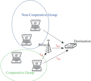
As shown in Fig. 2.1, the network scenario considered in the performance analysis con-sists of one destination, one fixed relay, and N user nodes. In general, the destination node can be regarded as an access point for uplink data transmission. In this thesis, instead of assigning mobile devices to serve as the relays for packet transmission, one fixed relay node is considered and exploited. The major reason is primarily owing to the excessive power consumption that will be incurred within the mobile devices while relaying packets for other network nodes. Furthermore, security issue and potential un-known movements are also concerns for adopting mobile devices for packet forwarding. In addition, the users in the network can be adaptively categorized into non-cooperative and cooperative groups depending on the transmission requirements. The users in non-cooperative group transmit data frames based on conventional direct transmissions; while those in cooperative group transmit their data frames via the assistance of relay node. The total number of nodes in the non-cooperative and cooperative groups are
Cooperative Group Non-Cooperative Group Destination Relay γSD γSR γRD
Figure 2.1: Network scenario with the combined direct/cooperative transmission scheme.
is adopted in the analysis. That is, the source transmits the data frame to both the relay and the destination in phase I. In phase II, the relay forwards the received data frame to the destination if the data is correctly decoded by the relay. Finally, the MRC method is utilized by the destination to combine the data frames from both the source and relay. Moreover, the channels between these network nodes are modeled as inde-pendent, flat Rayleigh fading, and zero-mean additive white Gaussian noise with unit variance. Each node is equipped with a single antenna where half-duplex transmission is assumed, i.e. simultaneously transmitting and receiving data frames is not considered
in the scenario. The parameters γSD, γSR, and γRD as illustrated in Fig. 2.1 denote
the instantaneous received signal-to-noise ratio (SNR) of the source-destination link, the source-relay link, and the relay-destination link respectively. Their corresponding
average received SNR values can be represented as σSD, σSR, and σRD.
In order to evaluate the throughput performance of the system which adopts both the direct and the cooperative strategies, the conventional model for the backoff
mech-0,1 0,2 0,W -20 0,W -10 1,0 1,1 1,2 1,W -21 1,W -11 m,0 m+1,0 m+r,0 m+r,W -2m m+r,W -1m m+1,W -1m m,W -1m m,2 m+1,2 m,1 m+1,1 m+r,1 m+r,2 m+1,W -2m m,W -2m 0,0 /W1 p /W1 p /W2 p /W2 p /Wm+1 p p/Wm+1 /Wm+2 p /Wm+2 p 1-p 1-p 1-p 1-p 1 1 1 1 1 1 1 1 1 1 1 1 1 1 1 1 1 1 1 1 1 1 1 1 1 1
Figure 2.2: Markov chain model for the backoff mechanism with the combined di-rect/cooperative strategy.
anism is adjusted to incorporate both the direct and cooperative schemes. The Markov chain model of the backoff mechanism is shown in Fig. 2.2. The backoff operation (s(t), b(t)) consists of two stochastic processes, where s(t) ∈ [0, m + r] indicates the backoff stage with the maximum m + r times of retransmission opportunities, and
b(t) ∈ [0, Wi] denotes the backoff timer whose maximum value at the ith stage can be represented as Wi = 2i· W 0 ≤ i ≤ m 2m· W m < i ≤ m + r (2.1) where W denotes the minimum contention window size. The parameter p as shown in Fig. 2.2 represents the probability of receiving an inaccurate frame at the destination. The unsuccessful reception of data frames at the destination is considered to result from either the frame collision or the transmission error. However, it is noted that the meaning of parameter p within the Markov chain model can be different in each node
depending on which group it belongs to. The parameters pdir and pcoop are introduced
as the probabilities of receiving an inaccurate frame at the destination via the direct and the cooperative transmission, respectively. Specifically, owing to different FER
values caused by different transmission schemes, the parameter p will be replaced by
pdir in the Markov chain model for nodes in the non-cooperative group. On the other
hand, pcoop will substitute the parameter p with nodes in the cooperative group. For
simplicity, the parameter p will still be utilized in some of the following derivations in the case that both groups share the same equations.
Furthermore, the transition probabilities, which are defined as Pt(i1, k1| i0, k0) ,
Pt(s(t + 1) = i1, b(t + 1) = k1| s(t) = i0, b(t) = k0), can be obtained as Pt(i, k | i, k + 1) = 1 k ∈ [0, Wi− 2], i ∈ [0, m + r] Pt(i, k | i − 1, 0) = Wpi k ∈ [0, Wi− 1], i ∈ [1, m + r] Pt(0, k | i, 0) = 1−pW0 k ∈ [0, W0− 1], i ∈ [0, m + r − 1] Pt(0, k | m + r, 0) = W10 k ∈ [0, W0− 1] (2.2)
Let πi,k , limt→∞Pt(s(t) = i, b(t) = k) be defined as the stationary probability with
i ∈ [0, m + r] and k ∈ [0, Wi− 1], the stationary probabilities can be correlated to π0,0
as follows: πi,k = WWi−ki · πi,0 k ∈ [0, Wi− 1], i ∈ [0, m + r] πi,0= pi· π0,0 i ∈ [0, m + r] (2.3)
Consequently, based on Pm+ri=0 PWi−1
k=0 πi,k = 1, the stationary probability π0,0 can be
obtained as π0,0 = " m X i=0 piw i+ m+r X i=m+1 piw m #−1 (2.4)
where wi = (Wi + 1)/2 and wm = (Wm+ 1)/2. The characteristics of the proposed
Markov chain model with combined strategy can be illustrated via (2.2)-(2.4) after p,
i.e. pdir and pcoop, can be obtained. The determination of these two probabilities is
explained as follows.
trans-mits within a randomly selected time slot, i.e. the conditional transmission probabilities
τdir and τcoop, can be respectively expressed as
τdir= m+rX i=0 πi,0 = π0,0 µ 1 − pm+r+1 dir 1 − pdir ¶ (2.5) τcoop = m+rX i=0 πi,0 = π0,0 µ 1 − pm+r+1 coop 1 − pcoop ¶ (2.6)
Let Pf (dir) and Pf (coop) denote the average FER resulted from the transmission error
through the direct and the cooperative transmission respectively. The following rela-tionships can be obtained:
pdir = 1 − (1 − Pf (dir))(1 − pc) (2.7)
pcoop = 1 − (1 − Pf (coop))(1 − pc) (2.8)
where the collision probability pc in (2.7) and (2.8) is acquired as
pc = 1 − [Rcg(1 − τcoop)Ncoop−1(1 − τdir)Ndir + (1 − Rcg)(1 − τcoop)Ncoop(1 − τdir)Ndir−1] (2.9)
with Rcg denoting the ratio of the node number in cooperative group to the total
number of interfering neighbors, i.e. Rcg = Ncoop/N. Therefore, it can be observed
that both pdir and pcoop are functions of the conditional transmission probabilities τdir
and τcoop. On the other hand, by substituting (2.4) into (2.5) and (2.6), the probabilities
τdir and τcoop can be represented as a function of pdir and pcoop respectively. As a result, the values of pdir, pcoop, τdir, and τcoop can be acquired through numerically solving the nonlinear equations (2.5) to (2.8).
Chapter 3
Throughput Analysis for
Direct/Cooperative Schemes
The saturation throughput based on the Markovian model as proposed in Section 2 will be analyzed and compared. The feasible occasion to adopt either the direct or the cooperative scheme will be explored under different channel conditions. In the first section, the FER values are calculated for both direct and cooperative strategies. The saturation throughput analysis is described in the second section; while the performance comparisons are conducted in the third section. In order to effectively enhance the system performance, the results obtained from the throughput analysis will be utilized in the design of feasible cooperative MAC protocols, which will be described in Chapter 4.
3.1
FER Calculation for Direct/Cooperative
Trans-missions
In this section, the average FER values through both the direct and cooperative links
(i.e. Pf (dir) and Pf (coop)) will be obtained from the average SNR values via their
corre-sponding channel conditions. The derivations from instantaneous SNR to its resulting FER value has been studied in [6, 30, 31]. Several influential factors are considered within their formulation, including the modulation type, coding strategy, channel con-dition, and frame sizes. In order to facilitate the derivation of throughput performance in the next section, an efficient model as proposed in [31] is utilized by adopting an
exponential relationship between the instantaneous FER Pf,ij and SNR value γij as
Pf,ij = α · e−gγij, γ ij > γt 1, γij ≤ γt (3.1)
where the subscript ij within the parameters represents the channel from node i to node
j. For example, as shown in Fig. 2.1, γSD indicates the instantaneous received SNR of the source-destination link associated with its corresponding instantaneous FER value
Pf,SD. Depending on different modulation and coding schemes, the parameters α, g,
and the threshold γt within (3.1) can be obtained from the least-square fitting method
as shown in [31]. Simply stated, the instantaneous FER Pf,ij can be derived from the
exponential function if the received SNR γij exceeds the threshold γt; otherwise, Pf,ij
is set to be 1. Moreover, due to the exponential distribution of the received SNR for Rayleigh fading channel, the probability distribution function (pdf) of the received SNR
γij can be acquired as
fΓij(γij) = 1
σij
where σij corresponds to the average received SNR of the channel from node i to node
j, i.e. σij , E[γij].
The average FER via conventional direct transmission, i.e. Pf (dir), can be derived
by calculating the average FER of the source-destination channel Pf,SD. By
consider-ing the relationship between instantaneous and average FER values over the channel
realizations, the average FER Pf (dir) from the direct link can be obtained as
Pf (dir) = Pf,SD = Z ∞ 0 Pf,SD · fΓSD(γSD)dγSD = Z γt 0 1 · 1 σSD e−γSD/σSDdγ SD+ Z ∞ γt αe−gγSD · 1 σSD e−γSD/σSDdγ SD = 1 − gσSD 1 + gσSD e−γt/σSD (3.3)
where fΓSD(γSD) and σSD are obtained as defined in (3.2). On the other hand, due to
the utilization of decode-and-forward scheme in cooperative communication, whether the relay can correctly decode the received data frame or not is required to be considered
for the derivation of Pf (coop). In other words, if the relay correctly decodes the received
data frame, the destination can combine two copies of the data frame from both the source and relay nodes. Otherwise, only one copy of the data frame will be received at
the destination. Therefore, the FER value Pf (coop) by adopting the cooperative scheme
is obtained as
Pf (coop) = (1 − Pf,SR) · Pf,(SR)D+ Pf,SR· Pf,SD (3.4)
where Pf,SD can be acquired from (3.3). Pf,SR represents the average FER from the
source to the relay and can be acquired similar to Pf,SD as
Pf,SR = 1 −
gσSR
1 + gσSR
Furthermore, Pf,(SR)D in (3.4) represents the average FER at the destination after combining the data frames from both the source and the relay. The calculation of
Pf,(SR)D can be acquired with the consideration of both source-destination and relay-destination channels as Pf,(SR)D= Z ∞ 0 Z ∞ 0 Pf,(SR)D· fΓSD(γSD)fΓRD(γRD)dγSDdγRD = Z γt 0 Z γt−γRD 0 1 · ( 1 σSD e−γSD/σSD)( 1 σRD e−γRD/σRD)dγ SDdγRD + Z γt 0 Z ∞ γt−γRD αe−g(γSD+γRD)· ( 1 σSD e−γSD/σSD)( 1 σRD e−γRD/σRD)dγ SDdγRD + Z ∞ γt Z ∞ 0 αe−g(γSD+γRD)· ( 1 σSD e−γSD/σSD)( 1 σRD e−γRD/σRD)dγ SDdγRD = 1 − · σRD σRD− σSD gσRD 1 + gσRD e−γt/σRD − σSD σRD− σSD gσSD 1 + gσSD e−γt/σSD ¸ (3.6)
It is noted that the benefit of adopting the exponential relationship between the FER and its corresponding SNR as in [31] can be observed. With the knowledge of both
channel conditions and estimated parameters α, g, and γt, the average FER Pf (coop)
through cooperative communication can therefore be derived as in (3.4). The results obtained above will be utilized to measure the suitability of cooperative communication compared to the direct transmission under a specific channel condition.
3.2
Saturation Throughput Analysis
The purpose of this section is to obtain the relationship between the SNR values and the resulting network throughput based on the results obtained from the previous sec-tion. For the derivation of throughput performance, a contention-based MAC protocol with cooperative communications is adopted. It is designed based on the IEEE 802.11 CSMA/CA scheme associated with the usage of the RTS/CTS exchanges. For the
purpose of informing the nodes in the network regarding the activation of cooperative communication, the new control frames named cooperative ready-to-send (cRTS) and cooperative clear-to-send (cCTS) are created. It is noted that the cRTS and cCTS fames have the same structures as the RTS and CTS frames respectively except the subtype field of MAC header. In other words, several reserved values of the subtype field in IEEE 802.11 standard can be utilized to create these new control frames for representing different control messages. Moreover, the channel will be secured to be collision-free after the exchanges of the RTS/CTS or the cRTS/cCTS frames as defined in IEEE 802.11 specification. Specifically, nodes in the cooperative group first initiate the delivery of the data frame by sending the cRTS frame in order to notify the other nodes for the request of cooperative communication. The cooperative communication will therefore be activated if the cCTS frame is issued by the corresponding destination. Subsequently, the source will transmit the data frame in the first phase to both the relay and the destination. The relay will forward the received data frame to the destination after a short inter-frame space (SIFS) duration, which completes the second phase of the cooperative scheme. On the other hand, nodes in the non-cooperative group will transmit their data frame based on the conventional RTS/CTS exchange for channel reservation. Due to the much smaller size compared to the data frames, the frame error of the non-data frames is considered neglected. It is noticed that the scheme mentioned above will be utilized as a preliminary evaluation of the saturated network throughput in the next section. Other contention-based MAC protocol with cooperative diversity can also be designed and analyzed in the similar manner.
Similar to the work presented in [19], the saturation throughput is defined as the fraction of time utilized to successfully transmit the payloads. In order to facilitate
the computation of the network throughput, two associated probabilities ptr and pwc
transmission occurs in the considered time slot, i.e.
ptr =1 − (1 − τcoop)Ncoop(1 − τdir)Ndir (3.7)
Moreover, pwc indicate the probability of a non-collided transmission on the condition
that at least one node is transmitting. It is composed by two probabilities pwc(cg) and
pwc(ncg), i.e. pwc = pwc(cg)+ pwc(ncg). The parameter pwc(cg) represents one node in the cooperative group reserves the channel while the other nodes remain silent during the
time slot, i.e. no collision occurs. On the other hand, pwc(ncg) represents that one node
in the non-cooperative group successfully reserves the channel and transmits its data frames. These two probabilities can be obtained as
pwc(cg) =
N ptr
[Rcgτcoop(1 − τcoop)Ncoop−1(1 − τdir)Ndir] (3.8)
pwc(ncg) =
N ptr
[(1 − Rcg)τdir(1 − τdir)Ndir−1(1 − τcoop)Ncoop] (3.9)
Furthermore, the saturation throughput S, which is defined as a function of Rcg, Pf (dir),
and Pf (coop), can be expressed as
S(Rcg, Pf (dir), Pf (coop)) =
E[LP]
E[TB] + E[TS] + E[TC] + E[TE]
(3.10)
The expected values within (3.10) are obtained as follows. E[TB] = (1 − ptr)δ indicates
the average duration of the non-frozen backoff time in a virtual time slot. It is noted that the virtual time slot represents the time duration between two consecutive backoff timers. The parameter δ is defined as the size of one slot time specified in the physical layer of the IEEE 802.11 standard. The average duration of the successful transmission
in a virtual time slot is acquired as
E[TS] = ptr[pwc(cg)(1 − Pf (coop))Ts(coop)+ pwc(ncg)(1 − Pf (dir))Ts(dir)] (3.11)
where Ts(dir) and Ts(coop) are the required time intervals for a successful transmission
via the direct and the cooperative communications respectively. These two parameters are obtained as
Ts(dir)=TRT S+ TCT S+ THeader+ TP ayload+ TACK+ 3TSIF S + 4ρ + TDIF S (3.12)
Ts(coop)=TcRT S + TcCT S+ 2THeader+ 2TP ayload+ TACK + 4TSIF S+ 5ρ + TDIF S (3.13)
where ρ is denoted as the propagation delay. It is noted that the meanings of the other
parameters are revealed by their corresponding subscripts, e.g. THeader indicates the
time interval for transmitting the header in a frame, and TDIF S corresponds to the
time duration of a distributed inter-frame space (DIFS). Moreover, E[TC] represents
the average time duration for the transmission with collisions in a virtual time slot. The mean duration of a failure transmission caused by the channel fading and noises is
denoted as E[TE]. Both E[TC] and E[TE] are obtained as
E[TC] =ptr(1 − pwc)Tc (3.14)
E[TE] =ptr[pwc(cg)Pf (coop)Te(coop)+ pwc(ncg)Pf (dir)Te(dir)] (3.15)
where Tc denotes the time interval for the transmission which occurs collision, i.e.
Tc = TRT S + ρ + TDIF S. On the other hand, the parameters Te(dir) and Te(coop) are
the required time durations to receive and detect the error frame caused from the channel fading and noises. Both values are considered the same as that for successful transmissions, i.e. Te(dir) = Ts(dir) and Te(coop) = Ts(coop). Finally, the parameter E[LP]
represents the average payload bits that is successfully transmitted in a virtual time slot, which can be acquired as
E[LP] = ptr{pwc(cg)(1 − Pf (coop))E[LP ayload] + pwc(ncg)(1 − Pf (dir))E[LP ayload]} (3.16)
where E[LP ayload] indicates the average length of payload bits in a data frame. Two
special cases for the saturation throughput S are considered as follows. Sdir represents
the saturation throughput if all of the nodes are in the non-cooperative group; while
Scoop indicates the case that the cooperative protocol is adopted for the entire system,
i.e. all the nodes are in the cooperative group. These two special cases can be defined as
Sdir ,S(Rcg = 0, Pf (dir), Pf (coop) = 0) (3.17)
Scoop ,S(Rcg = 1, Pf (dir) = 0, Pf (coop)) (3.18)
Whether it is suitable to adopt the cooperative schemes can be intuitively observed from the two extreme cases as described in (3.17) and (3.18). In general, the cooperative protocols can improve the FER with the cooperation of the relay, i.e. Pf (coop) < Pf (dir). However, the successful transmission time via the cooperative link is inherently longer
than that from the original direct communication, i.e. Ts(coop) > Ts(dir). Due to the
tradeoff between the FER and the required transmission time, there is no guarantee
that the saturation throughput from the cooperative communication (Scoop) will be
higher than that from the direct link (Sdir). The analytical models derived in this
section will be utilized to determine the suitable occasions to exploit the cooperative communication, as will be presented in the next section.
3.3
Throughput Comparison between Direct and
Cooperative Communications
Before describing the details of proposed protocols in Chapter 4, preliminary analyt-ical results will be observed and validated via simulations in this section. From the throughput perspective, the feasible situations to adopt either the cooperative or the conventional direction communication will be discussed. The saturation throughput
S(Rcg, Pf (dir), Pf (coop)) as defined in (3.10) can be obtained according to the average FER values computed via respective direct (i.e. from (3.3)) and cooperative links (i.e. from (3.4)). In order to validate the analytical model, the network scenario adopted in the simulations includes 30 user nodes with a fixed relay node. Table I illustrates the relevant parameters that are utilized in the analysis and simulations. Notice that
the parameters α, g, and γt in Table I can be obtained based on the least-squire fitting
method from [31] while the QPSK modulation is adopted. The other parameters are acquired from the IEEE 802.11a standard.
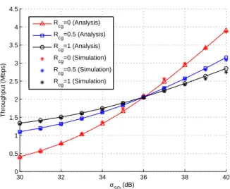
30 32 34 36 38 40 0 0.5 1 1.5 2 2.5 3 3.5 4 4.5 σSD (dB) Throughput (Mbps) R cg=0 (Analysis) Rcg=0.5 (Analysis) R cg=1 (Analysis) R cg=0 (Simulation) Rcg=0.5 (Simulation) R cg=1 (Simulation)
Figure 3.1: Throughput Performance versus the channel quality of direct link σSD under
various values of Rcg.
Table I : System Parameters
Approximation Parameter (α) 1.07439 Approximation Parameter (g) 0.000112484
SNR Threshold (γt) 28.0477 dB
Number of Nodes (N ) 30
Minimum Window Size (W ) 32
Maximum Backoff Stage (m) 5
Maximum Retry Limit (r) 2
MAC Header 224 bits
PHY Header 192 bits
cRTS/RTS (160+PHY Header) bits
cCTS/CTS (112+PHY Header) bits
ACK (112+PHY Header) bits
Payload 8184 bits Basic Rate 6 Mbps Data Rate 12 Mbps Slot Time 9 µs SIFS 16 µs DIFS 34 µs Propagation Delay 1 µs
Fig. 3.1 shows the throughput performance and validation under different values of
saturation throughput S is obtained from (3.10) under pre-defined channel conditions
of the source-relay and relay-destination links, i.e. σSD = σSD = 40 dB. Within the
total of 30 network nodes, the number of nodes in the cooperative group are selected
as 0, 15, and 30 which result in Rcg = 0, 0.5, and 1. In other words, there are Rcg
ratio of nodes in the network conducting their packet transmission based on cooperative
manner. As shown in Fig. 3.1. there exists a crossing point around 36 dB of σSD that
illustrates the decision point regarding the feasible situation to activate the cooperative communication. With a larger number of nodes within the cooperative group (e.g.
the curve with Rcg = 1), degraded throughput performance is observed as the average
SNR of the source-destination link σSD is larger than 36 dB. In other words, direct
transmission should be adopted under comparably better channel conditions between the source and destination since the exploration of cooperative communication will result in prolonged transmission time, which causes degraded effect on the throughput performance. Nevertheless, with a worse channel condition for direct link (i.e. below 36 dB in this case), the usage of cooperative communication will significantly improve the resulting throughput performance.
In addition, since coding schemes are not exploited in the derived analytical model,
the average SNR σSD shown in Fig. 3.1 will be in general overestimated. In other
words, the require SNR σSD for achieving the same throughput will be reduced while
a specific coding strategy is adopted. Therefore, similar trend as in Fig. 3.1 can also be derived with the exploitation of a specific coding scheme. Furthermore, it can be observed from Fig. 3.1 that the results obtained from both simulations and
analytical model coincide with each other under different SNR values of σSD. Noted
that the slight discrepancy at higher σSD values is mainly contributed by the usage of
approximated FER calculation presented in Section 3.1. Since the exponential function (as in (3.1)) results in faster decay in FER than that in realistic cases as the SNR values
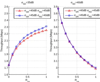
0 0.5 1 1.6 1.7 1.8 1.9 2 2.1 2.2 2.3 2.4 2.5 2.6 R cg Throughput (Mbps) σSD=35dB 0 0.5 1 3 3.1 3.2 3.3 3.4 3.5 3.6 3.7 3.8 3.9 R cg Throughput (Mbps) σSD=40dB σSR=40dB σ RD=45dB σSR=45dB σ RD=40dB σSR=40dB σRD=45dB σSR=45dB σRD=40dB
Figure 3.2: Throughput performance versus different values of the ratio Rcg (left plot:
worse direct channel quality σSD = 35 dB; right plot: better direct channel quality
σSD= 40 dB).
are increased, the throughput acquired from analytical model will possess slightly larger
value than that from simulations under higher values of σSD as in Fig. 3.1. However,
this negligible modeling difference does not deteriorate the advantage of exploiting the exponential FER approximation due to its simplicity and efficiency.
A closer examination of the dependency between the ratio Rcg and the
through-put performance is provided in Fig. 3.2. It illustrates the saturation throughthrough-put achieved by the combined direct/cooperative communication system, which includes several nodes conducting direct transmission while others transmit their packets via cooperative communication. The left plot shows the case with worse direct channel
quality (i.e. σSD = 35 dB); while better channel condition (i.e. σSD = 40 dB) is
il-lustrated in the right plot. As shown in the left plot in Fig. 3.2, it can be observed
that more nodes in the cooperative group, i.e. with larger Rcg value, will increase
the throughput performance under worse direct channel conditions. Conversely, the
throughput performance will be significantly degraded as the ratio Rcg is increased
plot of Fig. 3.2. Specifically, as the channel quality of direct link is good enough, trans-missions from the source directly to the destination is considered a better choice since the decreased FER resulted from the cooperative communication may not be signifi-cant. On the other hand, the prolonged transmission time induced by the cooperative communication can cause negative effect on the throughput performance. Therefore, whether a node should join the cooperative group depends on the channel qualities of the direct and cooperative links.
It is also noted that more throughput improvement can be achieved with better source-relay link compared to the relay-destination link. As shown in the left plot in
Fig. 3.2, the combination of σSR = 45 and σRD = 40 dB results in higher throughput
performance comparing with the case with σSR = 40 and σRD = 45 dB. This results
can be explained by the adoption of decode-and-forward scheme within cooperative communication. The source-relay link should provide good enough channel quality such that the relay can correctly decode the corresponding frame. Otherwise, full diversity gain will not be achieved with the exploration of cooperative communication. Therefore, the source-relay channel plays a more important role than the relay-destination channel for throughput enhancement, especially under poor channel quality of the direct link. In other words, as the source is suffering from severe fading channel and noises to the destination, a better source-relay channel is considered more important compared to the relay-destination channel in order to allow the destination to acquire another copy of data frames. This results will further be explored in the design of proposed BCC MAC protocol in order to provide efficient channel acquisition process, which will be explained in Chapter 4.
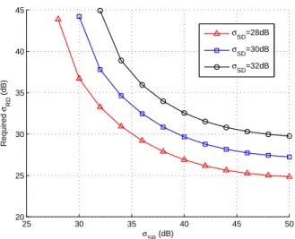
Fig. 3.3 shows the occasions for the cooperative mechanism to have a better per-formance than the direct communication under different SNR values. With pre-defined average SNR values of the source-destination and the source-relay channels, the
theo-25 30 35 40 45 50 20 25 30 35 40 45 σSR (dB) Required σRD (dB) σSD=28dB σSD=30dB σSD=32dB
Figure 3.3: Required average SNR σRD via cooperative communication for achieving the
same throughput as that with direct transmission under specific σSD and σSR values.
retically required average SNR of the relay-destination channel is obtained through the cooperative communication in order to have the same throughput as that via the direct
transmission, i.e. Sdir = Scoop where Sdir and Scoop are acquired from (3.17) and (3.18)
respectively. For each specific σSD and σSR, each point on the curves represents the
value of σRD that satisfies the following condition:
sup {σRD : Scoop(σSD, σSR, σRD) ≥ Sdir(σSD)} (3.19)
For example, as σSD = 30 dB and σSR = 40 dB, the cooperative scheme with σRD > 30
dB can outperform the conventional direct communication in network throughput. Each
curve in Fig. 3.3 can also be explained as the case while Scoop = Sdir for a specific
average SNR of the direct link. The region above the curve represents the situations of Scoop > Sdir. Moreover, it is especially noticed that Fig. 3.3 can be utilized as a reference plot to determine the suitability for adopting the cooperative schemes as opposed to the direct communication, which will further be explored in the design of cooperative MAC protocols in the next chapter.
Chapter 4
Proposed Cooperative MAC
Protocols
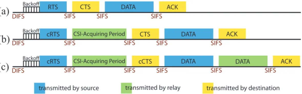
According to the analytical study as described in the previous chapter, whether to adopt either the direct transmission or cooperative communication depends on the variations of channel conditions. In order to improve the throughput performance, cooperative communication should be activated when the channel quality of direct link is compa-rably worse than that of the cooperative links, i.e. based on the criterion as illustrated in Fig. 3.3. Furthermore, a pre-specified single relay node is assumed to be available in the previous analysis. In realistic situation, how to select an appropriate relay node among the available network nodes is considered crucial for the improvement of net-work throughput. Based on the reasons mentioned in the previous section, fixed relays are also exploited in the design of proposed cooperative MAC protocols. For instance, several relay nodes can be pre-assigned and placed within the transmission range of an access point in order to assist for data transmission. The total number of required fixed relays can be determined based on the total numbers of users, the transmission range of access point, and the required system performance. The feasible locations and numbers
RTS CTS DATA ACK
Backoff
DIFS SIFS SIFS SIFS
cRTS CSI-Acquiring Period CTS DATA ACK
DIFS SIFS SIFS SIFS SIFS
transmitted by source transmitted by relay transmitted by destination cRTS CSI-Acquiring Period cCTS DATA DATA ACK
DIFS SIFS SIFS SIFS SIFS SIFS
Backoff Backoff
(a)
(b)
(c)
Figure 4.1: The schematic diagrams of both the handshake process and data trans-mission for (a) direct transtrans-mission in non-cooperative group, (b) direct transtrans-mission in cooperative group, and (c) cooperative transmission in cooperative group.
of relays within the network is considered pre-determined information, which is not within the scope of this thesis. Therefore, for the enhancement of throughput perfor-mance, the objectives for the design of proposed cooperative MAC protocols consist of the following: (a) to determine if cooperative communication should be employed, and (b) to select a feasible relay node based on the available relays within the network.
The schematic diagrams for the design of proposed MAC protocols are depicted in Fig. 4.1. It shows the transmission sequences including both the handshake and data transmission processes based on the combined direct/cooperative strategy. Noted that frames transmitted by either the source, relay, or destination are denoted with different color codes, e.g. frames with blue color are transmitted from the source. Moreover, the channel access method adopted in the proposed protocols is modified from the distributed coordination function (DCF) in IEEE 802.11 standard, where it is required for the source to contend for the channel usage before transmitting data frames to the destination. As shown in Fig. 4.1, the three different types of transmission processes in the proposed protocols are explained as follows.
(a) Direct transmission in non-cooperative group: Conventional DCF mechanism is exploited for the nodes in non-cooperative group. The source will initiate the trans-mission of RTS frame after the channel has been sensed in the idle state for the time
durations of both a DIFS and the backoff timer. After receiving the RTS frame, the other nodes within the network will set their corresponding network allocation vectors (NAVs) in order not to interfere with the on-going transmission between the source and destination. The data transmission will be started by the source after receiving the CTS frame transmitted by the destination. Successful reception of the acknowledge-ment (ACK) frame by the source will complete the packet transmission process.
(b) Direct transmission in cooperative group: Instead of initiating conventional RTS frame, the source within the cooperative group will issue the cRTS frame in order to notify the request of cooperative communication. However, the source does not possess enough information to determine whether to activate the cooperative communication or not. The decision to transmit via either the direct or cooperative communication is made by the destination after considering the instantaneous channel conditions. In order to conduct appropriate decision, it is required for the destination to acquire the channel state information from the relays, which is implemented within the CSI-acquiring period as shown in Fig. 4.1. In other words, the relays will utilize this period to transmit the channel information between the source and relays by adopting specific mechanism, i.e. the proposed FCC and ACC protocols, which will be described later in this chapter. It is noted that the destination can also obtain the channel condi-tions of the source-destination and relay-destination links by measuring the received control frames from the source and relays respectively. After acquiring the required channel information, the destination will make the decision to transmit data frames either through the direct transmission or through the help from relay. In the case that direct transmission scheme is notified by the decision metrics, the conventional CTS control frame will be forwarded from the destination to both the source and relays. It indicates that only direct communication between the source and destination should be utilized for data transmission.
(c) Cooperative transmission in cooperative group: Similar to the process as de-scribed in (b), this case also happens as the network nodes belong to the cooperative group. If the direct link is suffering from deep fading channel condition, cooperative communication will be determined by the destination after the CSI-acquisition period. The identifier of a relay that should participate in this cooperative communication will be filled in the cCTS frame, which will be transmitted by the destination in order to inform both the source and the chosen relay. Sequentially, cooperative communication for the two-phase data transmission will be activated, i.e. the source first transmits the data frame to both the source and selected relay, and it is followed by the data forwarding process from the relay to destination. It is noted that the duration between any frames is designed as a SIFS as shown in Fig. 4.1. After the cooperative combining process has been conducted by the destination, an ACK frame will be deliver to the source to complete the entire transmission procedures.
As described in both processes (b) and (c), it is required for the destination to determine whether the cooperative communication should be adopted. Based on the
saturation throughput as derived in Chapter 3, the instantaneous throughput SI(ζ)
is utilized as the decision metrics for the destination node, where the subscript ζ in
SI(ζ) denotes the different transmission schemes, i.e. SI(ζ) = {SI(coop), SI(dir)}. Since the decision metrics adopted in the destination should be implemented based on the realtime manner, the instantaneous throughput is simplified from combined average
throughput as derived in (3.10). First of all, the ratio Rcg is considered as 1 since
the destination needs to calculate the instantaneous throughput only for the nodes
in the cooperative group. The average successfully transmitted payload bits E[LP]
in (3.16) will become (1 − Pf (ζ))E[LP ayload], where the average length of payload bits
in a data frame E[LP ayload] is defined as in (3.16) and the instantaneous FER Pf (ζ)
(1 − Pf,SR)Pf,SRD+ Pf,SRPf,SD. Noted that the probability for at least one transmission
occurs in a time slot ptr and the probability of a non-collided transmission pwc in (3.16)
are both equal to 1 since the throughput SI(ζ) is considered at each instantaneous time
slot after some node has already reserved the channel. Moreover, instead of obtaining
the average time durations E[TB] E[TS], E[TC], and E[TE] in (3.10), the required
instantaneous transmission time TI(ζ) is obtained for the considered communication
schemes. The parameter TI(ζ), which include the handshake and data transmission
processes, can be estimated according to the ratio of the frame length to the data rate
for the corresponding scheme. Therefore, the instantaneous throughput SI(ζ) can be
obtained as
SI(ζ)=
E[LP ayload]
TI(ζ)
(1 − Pf (ζ)) (4.1)
It is noted that the instantaneous throughput SI(dir) and SI(coop) will be computed
directly within the destination by gathering the channel information during the
CSI-acquiring period. After CSI-acquiring the instantaneous throughput SI(dir) and SI(coop)with
different relays, the destination will determine if cooperative communication should be adopted. In the case that cooperative scheme is exploited, the destination will further select the most feasible relay for data forwarding based on the proposed FCC and BCC MAC protocols, which are described as follows.
4.1
Full CSI based Cooperative (FCC) MAC
Pro-tocol
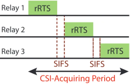
The design concept of the proposed FCC protocol is to provide full channel information of the potential relays such that the destination node can possess sufficient information to select a feasible relay node for data forwarding. As shown in Fig. 4.2, the control
Relay 1 Relay 2 Relay 3 rRTS rRTS rRTS SIFS SIFS CSI-Acquiring Period
Figure 4.2: The specific process in CSI-acquiring period with FCC protocol. frame named relay ready-to-send (rRTS) is created for carrying the channel information of the source-relay link from the relays to destination. It is designed to have the same structure as the CTS frame except that additional one-byte is added to store the channel information between the source and the relay. Moreover, since the relays are assumed to be deployed in advance, each relay can be assigned with a specific number representing its sequence to transmit the corresponding rRTS frame. According to the design of FCC scheme, the relays will transmit their rRTS frames sequentially within the CSI-acquiring period as depicted in Fig. 4.2. The channel quality between the source and the corresponding relay can consequently be delivered from the relay to destination. The SIFS durations are also assigned between the rRTS frames from different relays. After receiving all the channel information through the rRTS frames sending from the neighboring relays, the destination can therefore select a feasible relay node if cooperative communication is to be exploited.
4.2
Bitwise Competition based Cooperative (BCC)
MAC Protocol
Based on the design of the FCC scheme as mentioned above, it is beneficial to provide the available channel information via all different relays for the destination to
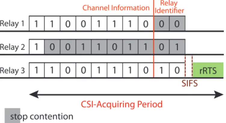
con-rRTS 1 0 1 1 1 0 1 1 0 1 1 0 1 1 0 0 0 0 0 1 1 1 1 0 1 1 1 0 0
Channel Information IdentifierRelay
Relay 1 Relay 2 Relay 3 stop contention 0 SIFS CSI-Acquiring Period
Figure 4.3: The specific process in CSI-acquiring period with BCC protocol. duct relay selection scheme. However, due to the elongated CSI-acquiring period, the throughput performance can be severely degraded if the total number of relay nodes are increased, i.e. excessive rRTS frames are to be delivered to the destination node. On the other hand, small CSI-acquiring period can result in the incompleteness of de-livering the channel condition from the relays to destination. Therefore, the design concept of proposed BCC scheme is to compromise between the overhead caused by the exchange of channel information and sufficient information for the destination to conduct suitable decisions. A pre-specified length of CSI-acquiring period is provided for the different relays to conduct the ”relay contention” process. The winner after the contention period will be the only relay to transmit the rRTS frame to the destination for reporting the channel condition of source-relay link.
As was discovered in the left plot of Fig. 3.2 that the channel quality of the source-relay link is more important than the link between the source-relay and destination in decode-and-forward scheme. Noted that similar results and observations can also be obtained in [6]. Therefore, without considering the relay-destination link, only the channel quality of the source-relay link is exploited to select the feasible relay for packet forwarding. As shown in Fig. 4.3, the bitwise competition in the CSI-acquiring period is designed to choose the appropriate relay, including 8 bits of channel information sequence and 2
bits of relay identifier. It is noted that every bit occupies one time slot which is defined in the IEEE 802.11 PHY layer standard. After receiving the cRTS frame transmitted from the source, the relays estimate their corresponding channel conditions for the source-relay links. The relays will transform the quality of the channel into an 8-bit channel information sequence, where better channel condition will be represented by a larger value of the channel information sequence. For example, an all ones 8-bit sequence indicates the best channel condition for the source-relay link. In addition to the sequence obtained from the channel quality, the relays also transform their specific identification number into the 2-bit relay identifier in order to avoid potential collision under the situations that two relays may have the same channel information sequence. Therefore, based on the channel condition and identification number, all the neighboring relays will initiate the relay contention process within the CSI-acquiring period. Noted that each bit value with one denotes that the corresponding relay will issue an active signal; while the zero value in a bit represents that the relay will keep silent and continue listening to the channel status during that slot.
For example, consider a three-relay scenario for explaining the proposed BCC proto-col, both the channel information and identification number are available for each relay as depicted in Fig. 4.3. All the three relays will transmit signals during the first slot; while only Relay 2 will become silent in the second slot. Relay 2 keeps monitoring the channel state in the second slot and detects that it is in the busy state. Consequently, Relay 2 will quit from the relay contention process since it realizes that there is at least one relay that has better channel quality of source-relay link. The remaining two relays will continue to contend to become the winner in the following slots. However, both relays possess the same channel condition which result in the same channel information sequence as indicated in Fig. 4.3. The purpose of the last two bits (i.e. the relay iden-tifier) comes into play in order to resolve for the potential contention between Relays 1
and 3. According to the identification numbers, Relay 3 will become the final winner within the relay contention process. An rRTS frame will be transmitted from Relay 3 to the destination in order to deliver the channel information of the source-relay link. Based on the decision metrics within the destination, either a CTS or cCTS frame will be transmitted by the destination in order to notify if the direct or the cooper-ative transmissions should be activated. The performance evaluation and comparison between the proposed FCC and BCC protocols will be conducted in the next chapter.
Chapter 5
Performance Evaluation
Numerical results are performed to evaluate the throughput performance of the con-ventional direct transmission and the proposed FCC and BCC protocols. The network scenario for performance evaluation and comparison is described as follows. Similar to Fig. 2.1, a single destination is assumed to locate at the center of the considered network, which confines a circular region with radius equal to 50 meters. The source nodes, which denotes the users, are randomly located within the area between 30 and 50 meters from the destination. It is assumed that all source nodes adopt the pro-posed protocols in order to observe the effectiveness of the propro-posed protocols when source nodes are far away from the destination. Based on the observation from [32], the suitable decision for relay deployment is to place the relays around the intermedi-ate location between the users and destination in order to appropriintermedi-ately enhance the network throughput. Therefore, stationary relays are uniformly distributed around the circle which is 20 meters from the destination. Various numbers of sources and relays will be considered under different simulation cases. It is also noted that the passloss exponent is set to be 4 in the following simulations. The other parameters adopted in the simulations is selected the same as in Table I.
30 32 34 36 38 40 2 2.5 3 3.5 4 4.5 σDB (dB) Throughput (Mbps) Number of Relays = 4 Number of Relays = 6 Number of Relays = 8
Figure 5.1: Throughput performance versus the average SNR value of boundary node
σDB using FCC protocol (number of sources = 30).
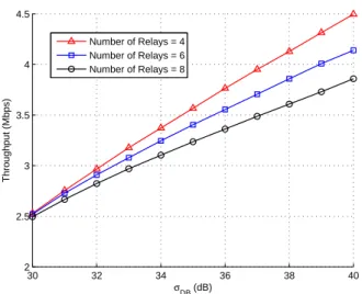
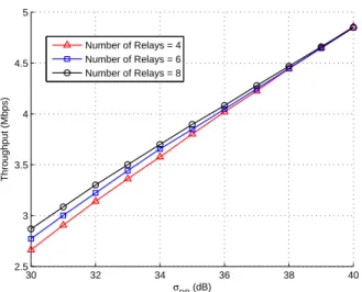
Figs. 5.1 and 5.2 illustrate the throughput performance for the proposed FCC and
BCC protocols respectively under different SNR values σDB. The parameter σDB is
defined as the average received SNR between the destination and a source located at the boundary of destination’s transmission range. Noted that the average received SNRs of other links can also be computed according to the distances of the links compared to
that located at the boundary with σDB. The total number of relays are selected as 4, 6,
and 8 in both cases; while that for the sources is chosen as 30. It is intuitive to observe in both figures that the throughput performance is increased with both schemes as the
value of σDB is augmented. However, in the proposed FCC protocol, the increased
number of relays will degrade the throughput performance as shown in Fig. 5.1. The main reason is due to the requirement to transmit additional rRTS frames by adopting the FCC method as the number of relays is increased. The throughput performance will consequently be degraded since excessive overhead are introduced by the elongated CSI-acquiring period. On the other hand, the throughput performance is enhanced as the number of relays is increased by exploiting the proposed BCC protocol. The
30 32 34 36 38 40 2.5 3 3.5 4 4.5 5 σDB (dB) Throughput (Mbps) Number of Relays = 4 Number of Relays = 6 Number of Relays = 8
Figure 5.2: Throughput performance versus the average SNR value of boundary node
σDB using BCC protocol (number of sources = 30).
reason is that the additional relays can provide data forwarding services for more users with the pre-specified fixed CSI-acquiring period. Even though only partial channel information are available by adopting the relay contention process within the BCC scheme, the resulting throughput performance can still be improved with augmented number of relays. Furthermore, as shown in Fig. 5.2, the throughput enhancement due
to the increased number of relays becomes insignificant as σDB is augmented, i.e. all
three lines converge as σDB is around 40 dB. This is attributed to the situation with
sufficiently good channel quality (i.e. with larger σDB values) where direct transmission
will mostly be activated by the destination. As a result, the number of relays will result in less impact on the throughput performance.
Figs. 5.3 and 5.4 are illustrated to compare the throughput performance of the pro-posed protocols with various number of relays. The total number of sources is selected
as 20, 30, and 40 for both cases. It is noted that the SNR value σDB is chosen as 30
dB for observing the effectiveness of proposed schemes under poor channel quality. It can be discovered that the throughput performance can be enhanced as the number of
1 2 3 4 5 6 7 8 9 10 2 2.1 2.2 2.3 2.4 2.5 2.6 2.7 Relay Number Throughput (Mbps) 20 nodes 30 nodes 40 nodes
Figure 5.3: Throughput performance versus the number of relays using FCC protocol
with different number of sources (σDB = 30 dB).
relays is smaller than 4 in both proposed protocols. However, as the number of relays is larger than 4, the throughput obtained from the FCC scheme decreases as the relay numbers are augmented. The BCC protocol, on the other hand, can still result in enhanced throughput performance as the number of relays is increased (in Fig. 5.4). Similar to the reasons as mentioned in the previous paragraph, the FCC protocol in-troduces more overhead by sending excessive rRTS frames as the number of relays is increasing. A harmful effect will occur when the control overheads can not be compen-sated by the enhancement of throughput resulted from the cooperative communication. In contrary, the BCC protocol will still be beneficial from the additional relays due to the limited CSI-acquiring period. Furthermore, similar trend can be obtained in both figures as the number of users is increased. The network throughput will be enhanced with the increasing of sources, however, the amount of improvement becomes smaller as the number of sources continues to grow.
Figs. 5.5 and 5.6 show the throughput improvement of the proposed protocols compared to the direct transmission under different number of relays and number of