Distribution system service restoration using the
artificial neural network approach and pattern
recognition method
Y .-Y. HSU H.-M. Huang
Indexing terms: Distribution systems, Restoration, Art$cial intelligence, Art$cial neural network, Pattern recognition
Abstract: Service restoration of a distribution system is investigated by using artificial intelli- gence. The purpose is to reach a proper resto- ration plan for the unfaulted zone after a fault has been identified and isolated. To reduce outage period and improve service reliability, the resto- ration plan must be devised in a very short period. In the paper, two approaches using artificial intel- ligence, i.e. the artificial neural network (ANN) approach and the pattern recognition method, are developed to determine the restoration plan in a very eficient manner. The effectiveness of the pro- posed approaches is demonstrated by the resto- ration of electricity service following a fault in a distribution system in Taipei, Taiwan. It is con- cluded from the example that a proper restoration plan can be reached very efficiently using the pro- posed approaches. Therefore, it can be used by distribution system operators to reach a resto- ration plan.
1 Introduction
Fault location identification [l-41 and service resto- ration [5-131 are important functions in the operation of a distribution system. After a fault event takes place, the interruption duration and the number of customers affected depend heavily on the effectiveness of the fault location identification algorithm and service restoration algorithm. Service reliability can be enhanced if the fault location is identified accurately and efficiently and a proper service restoration plan is reached in a short period after the fault has been isolated. How to devise a proper service restoration plan in an efficient manner is of major concern in this paper.
Since there are a great number of feeders, laterals, and switches in a typical distribution system, it may take a long time to determine the set of switches which must be operated in order to restore the electricity service in the out-of-service area if one tries to use one of the opti- misation techniques. Past experience and heuristic rules have been widely employed by the operators at many utilities including Taiwan Power Company (TPC) in order to reach a suboptimal solution in a short period.
0 IEE, 1995
Paper 1713C (P7), first received 17th May and in revised form 13th October 1994
The authors are with the Department of Electrical Engineering, National Taiwan University, Taipei, Taiwan, Republic of China I E E Proc-Gener. Transm. Distrib., Vol. 142, N o . 3, May I995
Rule-based expert systems and heuristic-based computer programs have been developed [5-131 to incorporate the human experts’ experience into the computer codes of service restoration.
In recent work completed by the authors [SI, a heuristic-based computer program has been developed to reach a restoration plan for the distribution system of TPC. It is concluded from the results in Reference 5 that a restoration plan which is able to restore as much load as possible by operating
a
minimal number of switches can be derived in an efficient manner. In a typical run, it takes about 2 minutes to execute the program in order to obtain the restoration plan.The above-mentioned rule-based expert systems or heuristic-based codes are widely used techniques in artifi- cial intelligence (AI), and have demonstrated many suc- cessful applications in the area of power systems. With the rapid developments in the field of artificial intelli- gence in recent years, a great number of new techniques have been reported. Among them, artificial neural net- works (ANN) [14-181 and pattern recognition methods [19-231 have received considerable attention from power engineers. The purpose of this work is to examine the feasibility of applying ANN and the pattern recognition method to reach a proper restoration plan.
To demonstrate the effectiveness of the proposed ANN approach and pattern recognition method, service restoration following a fault on a distribution system within the service area of Taipei City District Office of Taiwan Power Company is investigated. It is concluded from the test results that a proper restoration plan can be reached by the proposed ANN approach and pattern recognition method in a very short period. In fact, the required C P U time is much shorter than that required by the heuristic approach of Reference 5.
2 Problem formulation
Consider a typical underground distribution system in Taipei as shown in Fig. 1. Note that there is a normally
The authors would like to express their gratitude to the people at the Taipei City District Office of Taiwan Power Company for providing the valu- able system data and operational experience. Financial support given to this work by the National Science Council of Taiwan under con- tract number NSC 82-0404-E002-98 is appre- ciated.
closed switch for each incoming and outgoing line at each branching point as shown at branching point 7 of Fig. 1. The switches for other branching points are not shown in Fig. 1 due to limited space.
soon as possible. In other words, how can a limited number of troubleshooters be dispatched to the proper locations to operate switches such that the electricity service can be restored by the supporting feeder (SU73) LAT 1 5 ( S M 6 7 ) LAT 17 ( S M 7 0 ) LAT I E ( Z H 6 3 ) L A T Z O ( Z H 5 9 )
SW17 S W 9
L A T 1 4 ( S M 6 7 ) L A T I 6 (SM70) L A 1 19 (ZH59)
Fig. 1
S/S substation 0 branching point - feeder ~ lateral
*
lie switch n normally closed switch One-line diagram ofthe study systemIt is observed that feeder SM64 is connected with a supporting feeder SU73 through a normally open feeder tie switch SW9 which is a load break switch (LBS). The supporting feeder SU73 can be employed to supply power to feeder SM64 in case of an outage event on SM64 as long as it has enough spare capacity. In addi- tion, each of the eight laterals (LATl-LATI) is connected with a supporting lateral which can also be used to restore the load of a lateral. Of course, there may exist some laterals (LAT9, LATIO, LATll and LATl2) without supporting laterals. It is noted that we have to operate one switch (the feeder tie switch) in order to restore electricity service by using the supporting feeder. On the other hand, we need to operate two switches if we want to restore the electricity service on a lateral from its supporting lateral. For example, after the fault at point A on feeder SM64 has been isolated, the electricity service to customers on the twelve laterals LAT1-LAT12 is interrupted. To restore the electricity service to the twelve laterals, the operators can use the supporting feeder SU73 by closing the feeder tie switch SW9. If the sup- porting feeder does not have enough spare capacity to supply power to the twelve laterals LAT1-LAT12, the operators must select some additional supporting laterals to help restore electricity service. For example, we need to open the switch SWlO at branching point 7 and close switch SW1 (LBS) if we want to restore the electricity service on lateral LATl by using its supporting lateral LAT13. To avoid undesirable transient outage, we need to close switch SWl before opening switch SW10. Since the opening of switch SWlO and the closing of switch SW1 must be conducted at the same time, the two switches are referred to as the switch pair related to service restoration of lateral LATl. It is obvious that we need to operate a pair of switches when we try to restore the electricity service on a lateral by using its supporting lateral.
Since feeder automation projects at TPC are still under way, the switches must be operated manually. Therefore, the operator faces the problem of how to restore the electricity service to the twelve laterals as
252
and the supporting laterals LAT13, LAT14, LAT15, LAT16, LAT17, LATH, LAT19 and LATZO?
It is obvious that there are numerous solutions to the problem. Among these, a feasible restoration plan which meets all the six requirements described below [ 5 ] must be selected.
(1) The restoration plan must be reached in a very short time.
(2) Restore as much load as possible within the out-of- service area.
(3) The required number of switching operations in the restoration plan should be minimal. This is due to reasons related to limited troubleshooters and life expec- tancy of switches [SI.
(4) Only the switches which are close to the out-of- service area may be operated.
(5) Radial system structure must be retained.
(6) No feeders or laterals are overloaded. Therefore, only those supporting laterals with enough spare capac- ities can be employed to restore the loads of their corre- sponding laterals.
In Reference 5, a heuristic search algorithm was devel- oped to devise a proper restoration plan based on the operators’ heuristic rules. Test results indicated that proper restoration plans could be reached by the heuris- tic search method in a short time. In fact, the required CPU time on a personal computer was about 2 minutes.
In the present work, new approaches based on artifi- cial neural network and pattern recognition method are developed to reach the restoration plan. In general, an artificial neural network is made up of neurons connected together via links. A special feature of an ANN is its capability to solve a complicated problem very efficiently because the knowledge about the problem is distributed in the neurons and the connection weights of links between neurons and information are processed in paral- lel. Therefore, it is expected that the ANN approach will yield the desired restoration plan in a more efficient manner than the heuristic search approach in Refer- ence 5.
3
The artificial neural network employed in this work is a multilayer feedforward neural network [14, 151 as shown in Fig. 2.
Design of the artificial neural network
(on/off statesof tie switch&
I f output layer input layer inputs
223
(load 1, load 2, FM) Fig. 2 0, neuron output net, neuron rnputW,, connection weight o, neuron output
A multilayerfeedforward neural network
The nodes in the input layer receive input signals from the outside world and directly pass the signals to the nodes in the next layer. In this paper, the loads of the laterals within the out-of-service area and the spare capacity of the supporting feeder are taken as the inputs to the ANN. Details on ANN inputs will be provided at the end of this section.
The nodes in the output layer provide us with the on/off states of the feeder tie switch and lateral tie switches. These switch states indicate the set of switches that must be operated in the restoration plan as these switches are open in normal operation. A closed state for a feeder tie switch indicates that we need to restore the electricity service using the supporting feeder by closing the feeder tie switch. O n the other hand, a closed state for a lateral tie switch reveals that the lateral must be sup- plied power from its supporting lateral. Take the dis- tribution system in Fig. 1 as an example; we must close tie switch SW1 and open switch SWlO if the output state for the lateral tie switch SWl is closed. In other words, lateral LATl is now restored by its supporting lateral LAT13. In this way, the final restoration plan is described by the on-off states of the feeder tie switch SW9 and lateral tie switches SWl, SW2, SW3, SW4, SW5, SW6, SW7 and SW8. These on-off states of tie switches are generated by the nodes in the output layer of the ANN. Details on ANN outputs will be given at the end of this section.
In addition to the input layer and the output layer, we need one or more hidden layers in between. The nodes in the hidden layer take signals from the input layer and send their outputs to the nodes in the next layer when computations within the nodes have been completed.
I E E Proc-Gem Transm Distrib, Vol 142, No 3, May 1995
The connection weights
K j
between neurons are determined using a set of training patterns. A generalised delta rule [14] is employed to update the connection weights. Details on the determination of connection weights can be found in Reference 14.Details on the inputs and outputs of the ANN are described as follows.
1. The laterals within the out-of-service area are divided into three groups.
Group A : the laterals that can be completely resto-
Group B : the laterals that cannot be completely res-
Group C: the laterals which are not connected with
The laterals in group C are excluded from the inputs and outputs of the ANN since these laterals are not equipped with supporting laterals and can only be restored by the supporting feeder.
2. Assume that there are M group A laterals and (N-M-1) group B laterals in the out-of-service area for a particular training pattern. The lateral loadings and sup- porting feeder capacity margin can be described by the vector
(1) where I,,
..
.,
I, = loads for group A laterals, IY+,,. .
.,IN-,
= loads for group B laterals, and I, = the capacity margin of the supporting feeder minus the sum of the loads for group C laterals.Since the loads for group B laterals can only be resto- red by the supporting feeder, it is more appropriate to update the vector L to the new vector L: as follows.
red by their corresponding supporting laterals. tored by their corresponding supporting laterals. any supporting laterals via lateral tie switches.
L=[I,
,...,
J,MII,+,,...,
J N - l \ I N ] Tc
=[I;,
...,
r,
jI,,,,
...,
r,-,
j 1 3 T (2)where 1; =
Ii
for i = 1,. .
.,
M , I; = 0 for i =M
+
1,.
..
, N - 1, and I, = IN - (1,+,+
It is noted that, in eqn. 2, the loads on group B laterals have been restored by the supporting feeder. The result is a supporting feeder with less capacity margin for the group A laterals.
3. The vector L: in eqn. 2 may not be directly used as the input vector of the ANN since the elements in vector
L'
may fall outside the allowable range for the input signals. For the multilayer feedforward ANN in Fig. 2, both the inputs and outputs are limited to real numbers between zero and one. In practice, a range from 0.1 to 0.9 is normally recommended in the ANN literature. There- fore, the elements of the vector L are normalised accord- ing to the following equation to make them fall within the range from 0.1 to 0.9:(3)
+
...
+
I,-,).x
= [XI, x2,. . .
, XN]T where (4) x i = 0.8(*)
1'. -rmim
+
0.1 mar mmtax
andrmin
are the maximum value and minimum valueof I; (i = 1, 2,
. . .
, N). The resultant vectorX
is employed as the input vector of the ANN. Note that the above- mentioned normalisation procedures apply equally well to both training patterns and test patterns.4. In the training phase, the outputs of the ANN for the training patterns are defined as follows.
( 5 )
where yi = 0.1 if the lateral tie switch for lateral i is open,
y i = 0.9 if the lateral tie switch for lateral i is closed,
i = 1, 2,
. . .
,
N - 1; and y, = 0.1 if the feeder tie switch is open, y N = 0.9 if the feeder tie switch is closed.5. In the testing phase, the outputs of the ANN will be
real numbers ranging from 0 to 1. Since these outputs must provide information on the states of the lateral tie switches and feeder tie switch and there are only two pos- sible states (ON/OFF) for each switch, it is necessary to convert these real outputs to binary outputs. In the present work, an iterative procedure as described below is developed to do the job.
Step 1 . Set an initial value for the threshold p. A value of po = 0.7 is chosen.
Step 2. If an output is greater than or equal to p, set the output to be 1, which means that the corresponding switch must be closed. Otherwise, set the output to be 0 and keep the corresponding switch open.
Step 3. Check if any feeder or lateral is overloaded. If the answer is yes, decrease the value of p and go back to Step 2. Otherwise, stop and print out results.
It is noted that the required number of switching oper- ations will be increased if we decrease the threshold p. This is an undesirable situation as mentioned in Section 2. Therefore, we prefer to use a high threshold unless a feeder or lateral is overloaded due to insufficient number of switching operations.
4 The pattern recognition approach
In this section, we try to apply the pattern recognition approach [19-231 to reach a proper restoration plan. The pattern recognition approach involves three major steps.
Step I . Create training patterns.
Step 2. Store the training patterns in the database.
Step 3. Retrieve the patterns in the database which are similar to the pattern under study.
Details of the three steps are described as follows.
4.1 Create training patterns
A training pattern can be described as follows: training pattern
= (fault location, load, restoration plan) (6)
4.2 Store the training patterns in the database
Take the distribution feeder SM64 in Fig. 1 as an example, a training pattern in its original form may be expressed as
T = [section j LOAD,, LOAD,,
. .
.,
L O A D l 2 , L M , ,LM,, ..., LM,,, F M
I
SI,s,,
...)
S I , , SF]T (7) wheresection = fault location
LOADi (i = 1,
. . .
,
12) = total load of lateral LAT L M , ( i = 1,. . .
,
12) = capacity margin of the support- ing lateral for lateral LATFM = capacity margin of the supporting feeder for feeder SM64
Si (i = 1,
. . .
,
12) = on/off states of the lateral tie switch for lateral LAT(Si
= 1 if the switch is closed; Si = 0 if the switch is open)S, = on/off states of the feeder tie switch ( S , = 1 if the switch is closed; SF = 0 if the switch is open)
254
4.3 Retrieve the patterns in the database which are similar to the pattern under study
After the database has been built, we proceed to deter- mine a proper restoration plan for a given pattern.
5 Example
To demonstrate the effectiveness of the proposed ANN approach, service restoration on a distribution system within the service area of Taipei City District Ofice of Taiwan Power Company is investigated.
As shown in Fig. 1, the fault at point A is isolated by tripping circuit breaker CB1 and opening the switch at branching point 7.
It is observed from Fig. 1 that there ae 12 laterals to be restored electricity service. Among these, the eight lat- erals LAT1-LATB are connected with their supporting laterals through lateral tie switches. The feeder names for these supporting laterals are shown in Fig. 1.
In the training process, a total of 240 training patterns covering a wide range of lateral loadings and capacity margins of supporting feeders and laterals are compiled. As for the structure of the ANN, two hidden layers with 21 hidden units at each layer are used. In the training of the ANN, the learning rate q and momentum constant ci
are fixed at 1.0 and 0.5, respectively. In the experiment, we tried to use an ANN with a single hidden layer, but we were unable to obtain satisfactory results even when the number of neurons was increased to 42.
In the training process, the connection weights are updated each time a training pattern is presented. After the 240 patterns in the training set have all been present- ed once, one iteration of training is completed. At this time, the root mean squared error (RMSE) of the present
iteration is computed as follows:
where O i , j and Oi,jac,un, are the ANN output and the actual value of thejth neuron for the ith training pattern. After the RMSE for the present iteration is determined,
the 240 patterns are again presented in the next iteration. The process is repeated until the RMSE for an iteration
is less than a specified value. In the present example, the error is acceptable after 300 iterations.
After the ANN has been trained using the set of 240 training patterns in the training set, it can be employed to generate a proper restoration plan for a given oper- ating condition. To see how the ANN works in the test cases, results from a typical example are presented. The load currents on the feeder to be restored (SM64) and the supporting feeder (SU73) are listed in Table 1 while the
Table 1 :The load currents and capacity margin of the inter- rupted feeder (SM64) and the supporting feeder (SU73) in the example
Feeder Load current (A) Capacity margin (A)
= 450 - load current
SMW 2132 -
su73 212 230
capacity margins of the supporting laterals are listed in Table 2. In the present case, the seven laterals LATl- LAT7 are group A laterals since their corresponding sup- porting laterals are able to restore completely the loads on these laterals. As for the other laterals, lateral LATB is a group B lateral while laterals LAT9-LAT12 are group I E E hoc.-Gener. Transm. Disrrib., Vol. 142, No. 3, M a y 1995
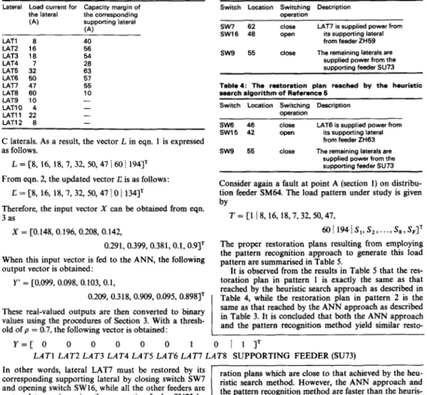
Table 2: The capacity margins of the supporting laterals Lateral Load current for Capacity margin of
the lateral the corresponding supporting lateral
(4
,A\
These real-valued outputs are then converted to binary old of p = 0.7, the following vector is obtained:
values using the procedures of Section 3. With a thresh-
LATl 8 40 LAT2 16 56 LAT3 18 54 U T 4 7 28 LAT5 32 63 U T 6 50 5 1 LAT7 47 55 LATE 60 10 LATS 10 - LATlO 4 - LATl1 22 - U T 1 2 8 -
C laterals. As a result, the vector L in eqn. 1 is expressed as follows.
L =
18,
16, 18, 7, 32, 50,47\
60\
1941' From eqn. 2, the updated vector C is as follows:C = [8, 16, 18, 7, 32, 50,47
\
0 j 1341'Therefore, the input vector
X
can be obtained from eqn. 3 asX = C0.148, 0.196, 0.208, 0.142,
Same as that reached by the ANN approach as described and the pattern recognition method yield similar resto- in 3. It is that both the ANN approach
Table 3: The restoration plan reached by the ANN Switch Location Switchino Description
In Other words, lateral LAT7 must be restored by its corresponding supporting lateral by switch
sw7
and opening switch sw16, while all the other feeders are restored to service using the supporting feeder SU73 byoperation
S W 7 82 close U T 7 is supplied power from
SW16 48 open it5 supporting lateral from feeder ZH59
ration plans which are close to that achieved by the heu- ristic search method. However, the ANN approach and the pattern recognition method are faster than the heuris- tic search method. both the heuristic search
s w 9 55 close The remaining laterals are supplied power from the supporting feeder SU73
Table4: The restoration plan reached by the heuristic search algorithm of Reference 5
Switch Location Switching Description
SW6 46 close U T 6 is supplied power from SW15 42 open its supporting lateral
from feeder ZH63 s w 9 55 close The remaining laterals are
supplied power from the supporting feeder SU73 operation
Consider again a fault at point A (section 1) on distribu- tion feeder
SM64.
The load pattern under study is given byT = [l
!
8, 16, 18,7,32,50,47,60 j 194 j SI, S , ,
. . .,
S,, SFITY = [ O 0 0 0 0 0 1 O I l - J T
LATl LAT2 LAT3 LAT4 LAT5 LAT6 LAT7 LAT8 SUPPORTING FEEDER (SU73)
I E E ' Proc.-Gener
Table 5: Summary of the restoration plans for the four feasible patterns
Pattern Tie switch states (1 =closed, 0 =open) Number of Total lateral loads
number switching restored by the
1 0 0 0 0 0 1 0 0 1 3 232
2 0 0 0 0 0 0 1 0 1 3 235
3 0 0 0 0 0 1 1 0 1 5 185
SW1 SW2 SW3 SW4 SW5 SW6 SW7 SW8 SW9 operations supportingfeeder(A)
4 0 0 0 0 1 1 0 0 1 5 200
ANN approach and the pattern recognition approach are described. The effectiveness of the proposed approaches is demonstrated by service restoration of an underground distribution system within the service area of Taipei City District Office of Taiwan Power Company. It is con- cluded from the results that proper restoration plan can be reached by the proposed ANN approach and pattern recognition method in a very efficient manner.
Just as the heuristic search method of Reference 5, the ANN approach gives a single restoration plan. On the other hand, the pattern recognition approach yields several restoration plans in the order of increasing number of switching operations.
The training phase of the ANN approach and pattern recognition method requires some time. In addition, the training of the neural networks must be repeated, and the database for the pattern recognition method must be updated any time there is a change in system configu- ration. Fortunately, neural network training and data- base updating are usually carried out offiine, therefore time is not a crucial factor at the training stage. After the ANN has been trained and the training patterns have been stored in the pattern recognition method, it requires only a very short period to obtain the desired restoration plan using the two approaches since only simple calcu- lations are involved in reaching the solutions.
In the underground distribution system of Taipei, any feeder is connected with a supporting feeder via a nor- mally open tie switch. The two feeders constitute a feeder pair which can be regarded as a unit. We need a separate ANN for each distribution feeder. As for the pattern recognition approach, a separate database is created for each distribution feeder. Therefore, the efficiency of the two approaches is independent of the size of the distribu- tion system. In a distribution system with three-terminal or four-terminal feeders, an ANN must be established for the group of feeders which are connected together. In this case, the size of the ANN or the database in the pattern recognition method will be somewhat larger than that of the ANN or the database used in this current work.
U p to now, substation automation has been com- pleted for all substations in the metropolitan area of Taipei. All substations in Taiwan will be automated in five years. The switches in an automated substation can be operated in a remote control mode by the operators at the distribution dispatch and control centre. Meanwhile, a feeder automation project has been initiated by Taiwan Power Company at three district offices and is expected to be completed in the near future. By the time the feeder automation project is completed, the switches on feeders will also be operated by remote control by the operators at the distribution dispatch and control centre. Therefore, for a distribution system with automated substations and feeders, the operators can change the on/off statues of the switches in a very short time. In this case, a decision period of two minutes seems to be a long time for the operators to wait before they or the computer can take actions to restore the electricity supply. Employment of the ANN method and the pattern recognition approach as an effort to reduce this computational time.
In the example, the load pattern used as the test pattern does not belong to the training set for the ANN method and the pattern recognition approach. It is observed from the results in Table 3, Table 4 and Table 5 that both the ANN and the pattern recognition method can still yield proper restoration plans which are close to that achieved by the heuristic search method. It seems that the ANN is capable of generating solutions for new
256
untrained patterns through some kind of ‘interpolation’ procedure.
7 References
1 DABBAGHCHI, I., and GURSKY, R.J.: ‘An abductive expert system for interpretation of real-time data’. Paper 92 SM 390-5 PWRD, presented at the IEEE/PES 1992 Summer Meeting
2 HSU, Y.Y., LU, F.C., CHIEN, Y., LIU, J.P., LIN, J.T., YU, H.S., and KUO, R.T.: ‘An expert system for locating distribution system faults’, IEEE Trans., 1991, PWRD-6, pp. 366-372
3 GIRGIS, A.A., and JOHNS, M.B.: ‘A hybrid expert system for faulted section identification, fault type classification, and selection of fault location algorithms’, JEEE Trans., 1989, PWRD-4, pp.
978-985
4 KUMANO, S., ITO, H., GODA, T., UEKUBO, Y., KYOMOTO, S., KOUROGI, H., and ARIUYA, Y.: ‘Development of expert system for operation at substation’. Paper 92 WM 225-3 PWRD, presented at the IEEE/PES 1992 Winter Meeting
5 HSU, Y.Y., HUANG, H.M., KUO, H.C., PENG, S.K., CHALLG, C.W., CHANG, K.J., YU, H.S., CHOW, C.E., and KUO, R.T.: ‘Distribution system service restoration using a heuristic search approach’, IEEE Trans., 1992, PWRD-7, pp. 734-740
6 TSAI, M.S., MESA, V.N., LIU, C.C., and HARTWELL, R.: ‘IOPADS (Intelligent operational planning aid for distribution system)’. Paper 92 SM 5 0 0 9 PWRD, presented at the IEEE/PES
1992 Summer Meeting
7 SHIRMOHAMMADI, D.: ‘Service restoration in distribution net- works via network reconfiguration’. Proceedings of IEEEjPES 1991
Transmission and Distribution Conference, pp. 626-632
8 SCOTT, W.G.: ‘Automating the restoration of distribution services in major emergencies’. Paper 89 T D 418-5 PWRD, presented at the IEEE/PES 1989 Transmission and Distribution Conference
9 LIU, C.C., LEE, S.J., and VENKATA, S.S.: ‘An expert system oper-
ational aid for restoration and loss reduction of distribution systems’, IEEE Trans., 1988, PWRDJ, pp. 619-626
10 AOKI, K., NARA, K., ITOH, M., SATOH, T., and KUWABARA, H.: ‘A new algorithm for service restoration in distribution system’. Paper 89 WM 085-2 PWRD, presented at the IEEE/PES 1989
Winter Meeting
1 1 RIZY, D.T., LAWLER, J.S., PAlTON, J.B., and FORTSON, N.H.: ‘Distribution automation applications software for the Athens Util- ities Board’, IEEE Trans., 1989, P W R D 4 pp. 715-723
12 HSU, Y.Y., JWO-HWU, Y., LIU, S.S., CHEN, Y.W., FENG, H.C., and LEE, Y.M.: ‘Transformer and feeder load balancing using a heuristic search approach’, IEEE Trans., 1993, PwRD-8, pp. 184- 190
13 HSU, Y.Y., and JWO-HWU, Y.: ‘Planning of distribution feeder reconfiguration with protective device coordination’, IEEE Trans.,
1993, PWRD-8, pp. 1340-1347
14 RUMELHART, D.E., HINTON, G.E., and WILLIAMS, R.J.: ‘Learning internal representations by error propagation’, in ‘Parallel distributed processing’, Vol. 1 (MIT Press, Cambridge, MA, 1986),
pp. 318-361
15 LIPPMANN, R.P.: ‘An introduction to computing with neural nets’, IEEE ASSP Mag., 1987, pp. 4-22
16 KIM, H., KO, Y., and JUNG, K.: ‘Artificial neural network based feeder reconfiguration for loss reduction in distribution systems’. Paper 92 SM 503-3 PWRD, presented at the IEEE/PES 1992
Summer Meeting
17 SANTOSO, MI., and TAN, O.T.: ‘Neural-net based real-time control of capacitors installed on distribution systems’. Paper 89
WM 768-3 PWRS, presented at the IEEE/PES 1989 Summer Meeting
18 CHAN, E.H.P.: ‘Application of neural-network computing in intelli- gent alarm processing’. Proceedings of 1989 PICA Conference, pp.
246-251
19 CHANG, C.S.: ‘Fast power system voltage prediction using knowledge-based approach and on-line box data creation’, JEEE Proc. C, 1989,136, pp. 87-99
20 CHANG, C.S., CHUNG, T.S., and LO, K.L.: ‘Application of pattern recognition technique to power system security analysis and optimization’. Paper 90 WM 178-4 PWRS, presented at the IEEE/ PES 1990 Winter Meeting
21 PANG, C.K., PRABHAKARA, F.S., EL-ABIAD, A.H., and KOIVO, A.J.: ‘Security evaluation in power systems using pattern rewgnition’, IEEE Trans., 1974, PAS-91, pp. 969-976
22 PANG, C.K., KOIVO, A.J., and EL-ABIAD, A.H.: ‘Application of pattern recognition to steady-state security evaluation in a power system’, IEEE Trans., 1973, SMC-3, pp. 622-631
23 OSTOJIC, D.R., and HEYDT, G.T.: Transient stability assessment by pattern recognition in the frequency domain’. Paper 90
WM146-1 PWRS, presented at the IEEEPES 1990 Winter Meeting IEE P r o c . - G e w . Transm. Distrib., Vol. 142, No. 3, M a y 1995