Analysis and Architecture Design of Block-Coding
Engine for EBCOT in JPEG 2000
Chung-Jr Lian, Student Member, IEEE, Kuan-Fu Chen, Hong-Hui Chen, and Liang-Gee Chen, Fellow, IEEE
Abstract—Embedded block coding with optimized trunca-tion (EBCOT) is the most important technology in the latest image-coding standard, JPEG 2000. The hardware design of the block-coding engine in EBCOT is critical because the operations are bit-level processing and occupy more than half of the compu-tation time of the whole compression process. A general purpose processor (GPP) is, therefore, very inefficient to process these operations. In this paper, we present detailed analysis and dedi-cated hardware architecture of the block-coding engine to execute the EBCOT algorithm efficiently. The context formation process in EBCOT is analyzed to get an insight into the characteristics of the operation. Column-based architecture and two speed-up methods, sample skipping (SS) and group-of-column skipping (GOCS), for the context generation are then proposed. As for arithmetic encoder design, the pipeline and look-ahead techniques are used to speed up the processing. It is shown that about 60% of the processing time is reduced compared with sample-based straightforward implementation. A test chip is designed and the simulation results show that it can process 4.6 million pixels image within 1 s, corresponding to 2400 1800 image size, or CIF (352 288) 4 : 2 : 0 video sequence with 30 frames per second at 50-MHz working frequency.
Index Terms—Block-coding engine, EBCOT, embedded block coding with optimized truncation, JPEG 2000.
I. INTRODUCTION
I
MAGE data compression is always indispensable, since the bandwidth and storage are limited and expensive. With the fast growing of multimedia market, million-pixel digital still camera (DSC), for example, is no longer unattainable, and bandwidth and storage are increasingly necessary due to the population of either wire-lined or wire-less network communication. JPEG [1], [2], a traditional but popular algo-rithm, has performed very well for natural image compression in the past. However, the blocking artifact in JPEG at low bit rates is very annoying. JPEG 2000 [3]–[9] is a newly proposed next-generation still-image-compression standard. It was finalized at the end of 2000 as an international standard, ISO/IEC 15 444-1 : 200 0. JPEG 2000 not only has better compression performance than the existing JPEG standard, but also provides many new features. It provides quality scalability, resolution scalability, region of interest (ROI) coding, and supports both lossless and lossy coding in the same framework.Manuscript received November 1, 2001; revised December 1, 2002. This paper was recommended by Associate Editor J.-N. Hwang.
C.-J. Lian, K.-F. Chen, and H.-H. Chen are with the Department of Electrical Engineering, National Taiwan University, Taipei, Taiwan, R.O.C.
L.-G. Chen is with the Graduate Institute of Electronics Engineering, De-partment of Electrical Engineering, National Taiwan University, Taipei, Taiwan, R.O.C. (e-mail: [email protected]).
Digital Object Identifier 10.1109/TCSVT.2003.809833
TABLE I
RUN-TIMEPROFILE FORJPEG 2000 ENCODERVM 7.2 [16] (IMAGE SIZE17922 1200, FIVE-LEVELWAVELETDECOMPOSITION, ONE LAYER, PROFILINGPLATFORM IS APIII-733 PC WITH128 MRAM,
MICROSOFTVISUALC++ 6.0ANDWINDOWSME)
Fig. 1. JPEG 2000 encoder functional block diagram. JPEG 2000 consists of three key modules, DWT, quantization, and EBCOT. EBCOT is a two-tiered coder.
These features are not available in baseline JPEG [1], but they are important for transmission requirements and applications in the networking era. However, the performance and new func-tionalities do not come without any price. The computational complexity of JPEG 2000 is much higher than that of JPEG. EBCOT [10]–[12], as one of the main modules in the JPEG 2000 standard, occupies over half of the computation time according to our experimental data (see Table I) [13] and other literature [5]. EBCOT is the most critical part in the design and implementation of a JPEG 2000 system.
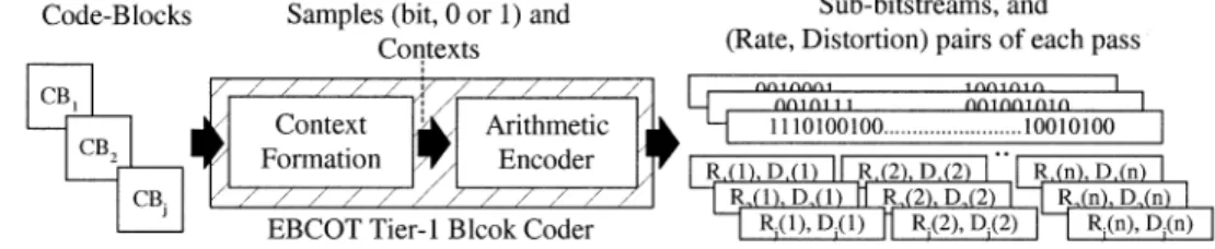
The block diagram of a JPEG 2000 encoder is shown in Fig. 1. Discrete wavelet transform (DWT) and embedded block coding with optimized truncation (EBCOT) are the two main techniques adopted. DWT is a subband transform, and it transforms images from spatial domain to frequency domain. The generated coefficients, which may be scalar quantized in lossy mode, are then entropy coded by the EBCOT algo-rithm. EBCOT is a two-tiered coder, where Tier 1 is actually a context-based adaptive arithmetic coder, and Tier 2 is for rate-distortion optimization and bitstream layer formation. After wavelet transform, coefficients in every subband are partitioned into code blocks. The inputs to Tier 1 are code block by code block, and the outputs of Tier 1 are arithmetic coded bitstreams for every code block. This is why Tier 1
Fig. 2. Illustration of the entire coding process of EBCOT Tier 1 block coder.
is called a block coder. After all code blocks are arithmetic encoded independently, Tier 2 collects all bitstreams with their rate-distortion information, and then picks more important bits first to form the final bitstream according to rate-distortion optimization criteria.
The reason EBCOT occupies the highest computation time is that the operations are bit-level processing. An -bit word becomes samples to be processed in EBCOT. Also, the fractional bit-plane processing further complicates the bit-scanning order. This bit-plane coding algorithm is difficult to be optimized on a general purpose processor (GPP) or digital signal processor (DSP). Therefore, dedicated hardware architecture for EBCOT block coder is imperative. Some preliminary commercial products of JPEG 2000 with dedicated modules for EBCOT Tier 1 have been announced in [14] and [15]. However, their technical details are not published. In [10], a reasonable architecture of the block-coding engine is discussed during the development of JPEG 2000. Later, more refinement and optimization concept of that initial structure is discussed in [4] and [12]. In this paper, we focus on the analysis of the EBCOT Tier 1 (block coder) algorithm, and propose an efficient accelerator, block-coding engine, for this most critical module. The main contribution of this work is the efficient hardware architecture based on the proposed speed-up techniques after the detailed analysis of the algorithm. Most significantly, the architecture is realized in a prototyping chip.
The rest of the paper is organized as follows. Section II re-views the algorithm of EBCOT tier 1, and Section III provides deep analysis of this block coder. Two speed-up methods are proposed according to those analysis results. In Section IV, the architecture based on these speed-up ideas is discussed. Ex-perimental results and performance comparisons are given in Section V. Conclusions are drawn in Section VI.
II. EMBEDDEDBLOCK-CODINGALGORITHM
EBCOT is a two-tiered coder, where the first tier is a block coder and the second tier is for rate-distortion optimization and bitstream formation. Although Tier 2 is part of the EBCOT al-gorithm, the practical implementation detail is not defined in the standard and not restricted in the design of an encoder. In this paper, we focus on the design of the block-coding engine for the first tier coding algorithm of an EBCOT encoder.
Tier 1 of EBCOT is actually a context-based adaptive arith-metic encoder. Code blocks are independently coded by this block coder into subbitstreams. According to the functionality, the block coder can be further partitioned into two steps, con-text formation (CF) and arithmetic encoder (AE), as shown in Fig. 2. The transformed coefficients of a code block are coded
Fig. 3. A sample is called “significant” after the first “1” bit is met while coding the magnitude part from MSB to LSB.
bit plane by bit plane from most significant bit-plane (MSB) to least significant bit-plane (LSB) instead of coefficient by coef-ficient. CF scans all bits within a bit plane of a code block in a specific order, and generates corresponding contexts for each bit by checking the status of the neighborhood bits. The AE then encodes each bit according to the adaptively estimated probabil-ities from its contexts. The outputs of the arithmetic encoder are the subbitstreams of each compressed code-block data. Also, the rate and distortion information are calculated for each pass for subsequent tier 2 processing.
Before CF, the quantized (in lossy mode) or nonquantized (in lossless mode) wavelet coefficients are converted from two’s-complement representation to sign-magnitude format. Let denotes the sign of the quantized wavelet coefficient , and
let denote the quantized magnitude, i.e., . If
the precision of is bit, then . We identify
the th bit of as , where . The th
bit plane of this code block is composed of the th bit of each sample in this code block. The scanning order in a code block is from the MSB of the magnitude part ( ) to the LSB ( ). A sample is called “significant” after the first “1” bit ( ) is met while encoding the magnitude part from the MSB to the LSB, and it is called “insignificant” before the first “1” bit appears, as illustrated in Fig. 3. The sign bit is coded immediately after the first “significant” bit is coded. Within a bit plane, every four rows form a “stripe,” and the scanning order is stripe by stripe from top to bottom. In every stripe, data are scanned bit by bit from top to bottom and column by column from left to right, as shown in Fig. 4. Also, the constitution ele-ments and hierarchy of a code block are summarized in Fig. 5.
To improve embedding, a fractional bit-plane coding method is used. Embedded coding, which is useful for scalability and for efficient rate control, is actually one of the main features
Fig. 4. Scanning order of context formation in every pass.
Fig. 5. Constitution elements and the hierarchy of a code block.
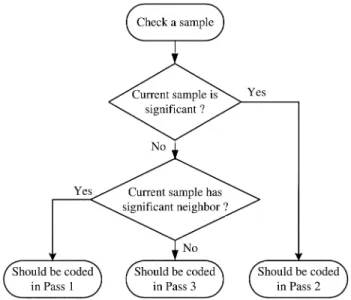
of JPEG 2000. Under this fractional coding method, one bit plane is further decomposed into three passes according to coef-ficients’ significant situations. While scanning from the top bit plane, all-zero bit planes are skipped. When the first nonzero bit plane is found, only pass 3 coding is used to encode all bits in this bit plane, since no bits will be coded in pass 1 and pass 2 according to the coding rule. The subsequent bit planes are scanned three times each following the scanning order de-scribed above. The first scanning is for pass 1, and is followed by pass 2 and pass 3 scanning. Each bit in a bit plane is encoded in one of the three passes. Pass 1 is named “significant prop-agation pass.” During pass 1 scanning, those samples that are currently insignificant, but have at least one immediate signif-icant neighbor are coded first. Clearly, these samples are most likely to become significant. Pass 2 is called a “magnitude-re-finement pass.” Samples that have become significant in pre-vious bit planes are coded in this pass. The last pass, pass 3, is a “clean-up pass.” Samples not coded in the first two passes are coded in this pass. As the example shown in Fig. 6, the two bits that are coded in pass 2 in this bit plane have become signif-icant in the previous bit plane. Those bits coded in pass 1 are near those two pass 2 positions due to the significance propaga-tion characteristic.
Once a bit is checked and decided to be coded in one pass, its context is generated according to the status of its neighbors using four coding primitives: zero coding (ZC), run-length coding (RLC), sign coding (SC), and magnitude refinement (MR) primitives. There are a total of 19 contexts defined in JPEG 2000 [3]. The context of a bit should be generated and sent to arithmetic encoder along with the bit to be coded. Among the four coding primitives, ZC and SC primitives are used in the first and the third pass, MR primitive is used in the second pass only, and RLC primitive is used in the third pass. ZC and MR primitives check the eight immediate neighbors’ significant states to decide the context, and the RLC primitive is applied when the four bits in a column do not have any significant neighbors. The SC primitive has to check the four (horizontal left and right, and vertical up and down) immediate neighbors’ sign and significant states.
Fig. 6. Example of fractional bit-plane coding. There are three passes in a bit plane. Each bit is coded in one of the three passes.
Fig. 7. Evolution map of the bits in a sample from higher bit planes to lower bit planes.
After the context is generated, the arithmetic encoder will code the bits (decisions) based on their associated contexts. Arithmetic coding is widely used in some standards. JBIG [17] and JPEG both describe the QM coder, while JPEG 2000 and JBIG-2 both use the MQ coder. There are quite a number of important differences between MQ and QM from an imple-mentation perspective. Most notably, the MQ coder lends itself to more efficient hardware implementations, since it replaces full carry resolution (difficult to implement, having unbounded delay implications) with a bit-stuffing technique. The MQ coder also has a smaller probability table. In JPEG 2000, the probability estimation and update process is accomplished by a table lookup method, and hence no multiplication is necessary. The probability estimation table, containing the information of the estimate of the less probable symbol’s probability (Qe), Next state if More Probable Symbol is coded (NMPS), Next state if Less Probable Symbol is coded (NLPS), and SWITCH, is fixed and predefined in the standard. After arithmetic encoding, the output is an arithmetic coded bitstream, which consists of many pass segments with the rate and distortion information for each pass. These data are the output of the first tier, and send to Tier 2 for further selection to form the final JPEG 2000 bitstream.
III. ALGORITHM ANALYSIS AND PROPOSED
SPEEDUPTECHNIQUES
According to the profile data in Table I, the block coder oc-cupies most of the computation time, and thus this bit-level pro-cessing task deserves a detailed analysis. In [10], a straightfor-ward architecture is considered. Each bit is checked for three
TABLE II
STATISTICALDATA OFNUMBER OFBITSCODED INEACHPASS OF A2562 256 LENAIMAGEAFTERTWO-LEVEL 5/3 DWT WITHOUTQUANTIZATION. SIGNBITS ARENOTCOUNTED INTHISDATA. BIT-PLANE0IS THELSB
times, one for each pass, although each bit will only be coded in one of the three passes. Coding a 64 64 code block with magnitude bit planes will cost at least 64 64 3 clocks. This will generate many “bubbles” if the block coder scans and checks every bit in this way. That makes the block-coder design very inefficient.
According to the observations on the context formation process, improvements on processing cycles can be achieved by utilizing some characteristics. Fig. 7 shows the “evolution” of the bits of each sample among the three passes during the block coding. Every sample is insignificant in the first bit plane, so all bits in the first bit plane are coded in pass 3 in the beginning. As we proceed coding toward lower bit planes, some samples become significant. The following bits of that significant sample will then all be coded in pass 2, and their insignificant neighbors will be coded in pass 1 due to the significance propagation prediction.
Fig. 8. Distribution of the number of bits coded in the three passes in every bit plane. The distribution shown in this figure is a 642 64 code block from the HH subband of the highest resolution in a 2562 256 Lena image after two-level wavelet decomposition (the bottom right one in Table II).
TABLE III
COLUMNSCLASSIFIED BYHOWMANYNBC SAMPLES ACOLUMNCONTAINS (BABOON, 5122 512, FIVE-LEVELWAVELET, CODE-BLOCK642 64)
Fig. 9. Concept of SS speedup method. Skip no-operation samples in a column, and directly encode NBC samples.
Fig. 10. Concept of GOCS method. A group of no-operation samples are skipped together.
The characteristic of the context formation process makes the distributions of the number of bits coded in the three passes vary greatly from bit plane to bit plane, i.e., highly skewed distribu-tions. Real cases are analyzed and Table II shows the detailed distributions of the 16 code blocks in a Lena image. One of the distributions of a code block is drawn in Fig. 8. In the MSB, bit-plane number 5 in this example, all samples are insignifi-cant, and thus 4096 bits are coded in pass 3. In lower bit planes, more and more bits are coded in pass 2, while the number of bits in pass 3 is decreasing. The number of bits coded in pass 1 increases at the beginning, and then decreases because for the samples coded in pass 1, some of them could become signifi-cant in this pass and will be coded in pass 2 in the following bit planes. The bits to be coded in one pass may be very sparse. Some passes may even do not have any bits, such as pass 3 of bit-plane 0 in some code blocks in Table II. This distribution phenomenon is utilized for architecture optimization.
The problem of the block coder is the inefficient processing flow of the sequential bit-level processing and irregular coding patterns due to the fractional bit-plane coding. To speed up the processing, we can make effort on two ways. First, speed up the time required to process need-to-be-coded (NBC) samples by generating more than one context and decision (bit) every cycle. The second method is to skip those bits not belonging to that pass. Since arithmetic encoder can encode at most one sample
Fig. 11. Example of GOCS: four columns are grouped together in this example. The numbers in the bottom are the clock cycles required to encode these bits.
Fig. 12. Run-time analysis with different number of columns as a group. C program simulation of context formation with SS and GOCS techniques.
Fig. 13. Block diagram of CF module.
per clock cycle due to the probability adaptive characteristic, it does not make sense to generate more than one context and sample pair as the first method suggested. Therefore, we focus our design strategy on skipping those “bubbles” while scanning those sparse passes.
Fig. 14. Block diagram of the proposed column-based significant state variables PE.
Bubble removal and data reuse can be achieved via column-based operation. In the architecture discussed in [10], data are supplied to context formation processing element (PE) one bit at a time, i.e., sample-based serial checking. Since the sample under checking may not belong to this pass, the checking, therefore, results in a “bubble.” The bubbles can be efficiently removed by checking more than one sample every clock cycle as long as at least one bit in this checking belongs to this pass. In the proposed architecture, column-based operation is adopted instead of sample-based operation. There are two advantages of column-based operation. First, bits in a column are checked simultaneously, so “bubbles” can be skipped. Second, higher data reuse in significant and sign state variables, and thus memory access frequency of these state variables can be reduced. This will be clearer after the discussion of the proposed hardware architecture in the later section.
In every bit plane, each bit is coded in one of the three passes, so one column in every pass may contain 0–4 NBC samples. Table III shows the experimental result based on the column-based concept. In this experiment, columns in every pass are classified according to number of NBC pixels in them. For example, there are 181 076 columns in pass 1, 159 223 columns in pass 2, and 258 328 columns in pass 3 that do not contain any NBC samples. There are total 598 627 (47.85%) columns contain zero NBC samples. The percentage of columns having four NBC pixels, which means no processing cycle is wasted in a sample based serial checking architecture, is only 22.06%. According to the sample based serial checking architecture, checking a column costs four clock cycles no matter how many NBC samples are in it. Our key ideas are to improve this phenomenon by 1) skipping no-operation samples and 2) skipping no-operation columns (columns without any NBC sample). Two speedup methods are described below.
A. Sample Skipping (SS)
SS skips no-operation samples in a column, as illustrated in Fig. 9. It can be applied to all three passes. Through parallel checking, if there are NBC samples in a column ( ), only cycles will be spent on coding these NBC samples, and cycles are saved. Suppose there is not any NBC sample in a column, only one cycle is spent on the checking. Since most columns have less than four NBC samples, this method can
im-Fig. 15. Flowchart of coding a column using sample skipping speedup method.
Fig. 16. Control circuit of SS method.
prove the cycle time greatly, as the experimental results show in Section V.
B. Group-Of-Column Skipping (GOCS)
GOCS is to skip a group of no-operation columns together, as shown in Fig. 10. It can be applied to pass 2 and pass 3. After ap-plying this technique, both the processing cycles and the number
of memory access can be reduced. The number of NBC samples in each group can be checked and recorded while coding in pass 1. A 1-bit tag is used for each group. For example, a “0” bit is recorded in the GOC memory if a GOC has no NBC samples. Otherwise, a “1” bit is recoded. While coding pass 2 and pass 3, the tags in GOCS memory are checked. If the tag is “0” for current coding GOC, all columns of this group can be directly bypassed instead of checking one by one. Fig. 11 is an example of a 16-column stripe with four contiguous columns grouped to-gether. The tag for every GOC is generated while coding pass 1, and stored in GOCS memory. While coding pass 2, those GOC with tag “0” are directly skipped, which costs only one clock cycle. The GOC with tag “1” is then checked column by column, and coded using sample skipping method. To decide how many columns should be grouped together, different images are used for C model simulation. The simulation result in Fig. 12 shows that eight columns as a group has the best run-time performance in all test patterns.
As an extreme case of a skipping technique, pass skipping is possible. Suppose samples become significant in the earlier bit plane; it is possible that all samples become coded in pass 1 and pass 2, and thus no samples are in pass 3. Another possibility is that all samples in the lower bit planes belong to pass 2, and none to pass 1 and pass 3. In these cases, the whole pass (pass 1 and/or pass 3) can be skipped. Although the occurrence prob-ability of these cases is not high, pass skipping is efficient once it happens, since the whole pass is skipped. Besides, the most important fact is that the implementation overhead for pass skip-ping is quite small, since only a 1-bit flag is necessary to record this information, and the checking and control circuits are very simple.
IV. ARCHITECTURE
A cycle-efficient block-coding engine for EBCOT Tier 1 in JPEG 2000 is proposed in this section. The detailed architec-tures of the context formation and arithmetic encoder modules are described in the following subsections.
A. Context Formation Module
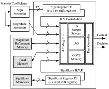
The block diagram of context formation is shown in Fig. 13. In the top left corner, there are two code-block data memories: one is for sign bits and the other is for magnitude bits. Three state variables, which are necessary for the context formation algo-rithm as defined in [4] and [10], are stored in the three memories shown in the bottom left corner. The variables in magnitude
re-finement memory are used to provide the information whether
the sample in this pass is coded in significant refinement pass for the first time. The final memory traces the information that each sample has been coded or not so far in this bit plane. The
significant memory stores the information whether one
coeffi-cient has become significant or not. The wavelet coefficoeffi-cients and state variables corresponding to current coding column are sent to coding PEs for generating context (CX) and decision (D) using four different coding primitives. Since sign bits and significant state variables of neighboring samples are required while coding these variables are sent to sign register PE and
significant register PE for pre-processing before submitted to
Fig. 17. Flowchart of sample checking to determine which pass a sample belongs to.
Fig. 18. Examples of some feasible memory arrangements for significant state variables.
Fig. 19. Proposed memory arrangement for significant state variables.
coding PEs. The SS sample selector, which is used for sample skipping speedup method, generates the index of NBC samples one by one for coding PEs. The address generator (AG) gener-ates read and write addresses for all memories and register PEs. The GOCS memory is used to store the information required by GOCS speedup method. CX and D generated by four coding PEs are transmitted to the pass controller for selection. A small buffer, as a parallel to serial converter, is placed to smooth the data flow, and CX and D pair are outputted to AE one by one.
Fig. 20. Data flow of arithmetic encoder with four-stage pipeline.
The block diagram of significant register PE is shown in Fig. 14. The rectangles stands for a shift register array for sig-nificant state variables. It can provide not only the sigsig-nificant state variables needed, but also the sum of significant neigh-bors of each sample in current coding column simultaneously. After finishing coding a column, variables in the register array are shifted to the nearby column on the left for the coding of the next column. The original variables in the left column are aban-doned, and new variables are loaded from memory and stored in the right column. Because of results sharing, a hardware cost for column-based operation can be reduced.
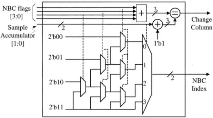
Fig. 15 is the flowchart of coding a column using sample skip-ping speedup method. NBC samples are coded one by one until all NBC samples in this column are coded. Therefore, to imple-ment the sample skipping method, indexes for NBC samples in this column must be generated one by one. The control circuit for sample skipping is shown in Fig. 16. In this figure, the 4-bit NBC flags indicate which samples in the current coding column are NBC samples, for example, the four bits “1010” mean that the first and third samples are NBC ones. The 2-bit Sample Ac-cumulator accumulates the number of samples already coded in this column. The NBC index of the current coding sample is generated after the multiplexers selected by NBC flags and Sample Accumulator. The Change Column signal is activated while the number of NBC samples in a column equals the accu-mulated number of coded samples, which means that all NBC samples in this column have been coded.
To implement GOCS, we have to find out which sample has to be encoded in pass 2 and pass 3 during the scan of pass 1. Besides, we have to record a tag in GOCS Memory if this GOC can be skipped. The flowchart for checking a sample is shown in Fig. 17. We can determine which pass a sample belongs to by the two decisions. Then, if a GOC (eight columns in our design) can be skipped, the next column to be encoded is the address of the current column added by eight. If a GOC cannot be skipped, every column in this GOC has to be coded one by one. Since the hardware required for checking and skipping is quit simple, the hardware overhead for GOCS is dominated by the GOCS
memory. Eight columns are chosen as a group according to the
analysis data in Section III. For a 64 64 code block, there are 1024 columns, so there are 128 GOCs. Every GOC requires two bits to record the tags for pass 2 and pass 3, respectively. Thus, a 256-bit GOCS memory is required in our design.
Memory arrangement is a nontrivial issue for context forma-tion. For coding a single sample, nine significant state variables
are required, including variables of the sample under coding and the eight neighboring samples. In a column-based design, 18 significant and sign variables are needed at the same time for a coding PE, including current and two neighboring columns, with six bits for each column. Since variables from neighboring stripes are needed, it is quite a challenge to arrange and access memory. Two feasible memory arrangements are shown in Fig. 18. For arrangement A, four variables of a column are grouped to be a word. These words are interleaved placed in three memories. Every time a new column is processed, three words, including the current coding column, the upper one, and the lower one, have to be loaded from three memories, one word per memory. Therefore, the memory bit-width is 12 bits. However, some redundant variables are also loaded from the memory. Only six variables are needed for coding a new column, but 12 variables are accessed. The memories must also be written if there are any changes in significant state. During write access, only the current column has to be written back, therefore, there is no redundancy in write cycle. For arrange-ment B, variables are interleaved placed in two memories. Every time a new column is processed, two words are loaded from two different memories. Thus two redundant variables are loaded. Each time the data have to be written back to memory, there will be four redundant bits. In summary, arrangement A reads six redundant bits in every 12, but writes no redundant bits, while configuration B reads two redundant bits and writes four redundant bits. In our design, a novel memory arrangement for significant state variables is proposed. Every four variables are grouped to be a word as shown in Fig. 19, and words are placed in three memories in an interleaving format (A, B, C, B, A, B, C, B, C, B, A). Using this arrangement, variables of two nearby columns are loaded into the register together in one cycle. Although the memory bus width is also 12 bits, the memory access frequency is reduced to half, and no redundant variables are loaded. As for memory writing, there will be 4-bits redundancy for the write back of two columns data. Compared with arrangement A and B, our configuration has two redundant bits access for one read and write of one column, while arrangement A and B both have six redundant bits.
B. Arithmetic Encoder Module
Arithmetic encoding comprises a series of additions and update operations. The architecture of the arithmetic coder is a mapping of the flowcharts in Annex C of JPEG 2000 standard
Fig. 21. Detailed block diagram of the arithmetic encoder.
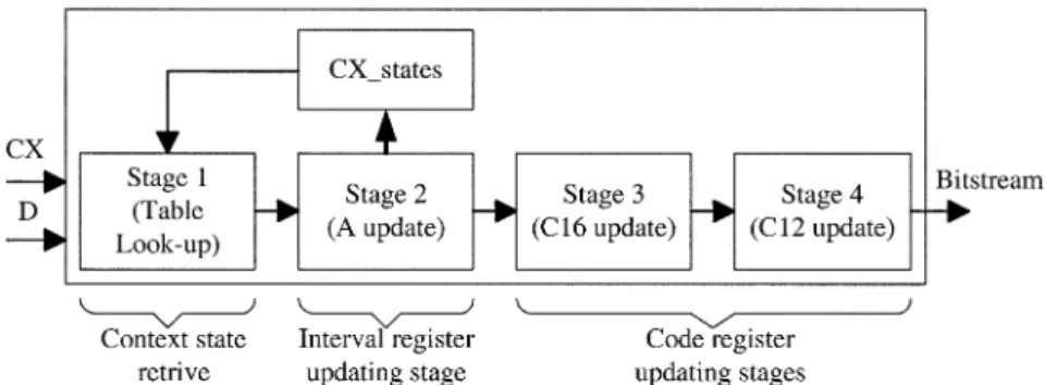
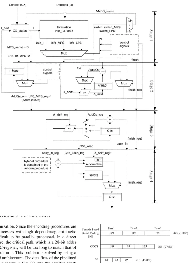
[3] with some optimization. Since the encoding procedures are inherently serial processes with high dependency, arithmetic coding is very difficult to be parallel processed. In a direct mapping architecture, the critical path, which is a 28-bit adder used to update the C-register, will be too long to match that of the context formation unit. This problem is solved by using a four-stage pipelined architecture. The data flow of the pipelined arithmetic encoder is shown in Fig. 20, and the detailed block diagram is shown in Fig. 21.
The input data to the arithmetic coder are Context (CX) and Decision (D). In stage 1, the probability (Qe) of current input CX is loaded from the CX state table. Besides, the more prob-able symbol (MPS) of the current input CX is also checked from the MPS table contained in CX_states to see if the cur-rent MPS sense is “0” or “1.” Note that the estimated proba-bility of this context will be updated by the feedback
informa-Fig. 22. Performance comparisons (clock cycles required).
tion from stage 2. To deal with the case when two identical con-texts come in continuously, a look-ahead approach is adopted to
TABLE IV
COMPARISON OFCLOCKCYCLESREQUIREDBETWEENSAMPLE-BASED AND COLUMN-BASEDARCHITECTURES. INOURCOLUMNBASEDARCHITECTURE,
BOTHSSANDGOCS TECHNIQUES AREAPPLIED
avoid the conflict. Stage 1 will therefore provide stage 2 with the look-ahead probability estimations. The main function of stage 2 in this arithmetic encoder is to update the interval, that is, the information kept in the A-register. The new interval will be the one selected from either Qe or A Qe, depending on whether LPS or MPS is coded. Notice that the critical path of this stage is the one through a 16-bit subtractor (A Qe) and the re-nor-malization operation. Since the value of the A-register must be kept in the range of 0x8000–0xFFFF, a re-normalization oper-ation (shift to the left) for A-register will be performed if the value falls below the value 0 8000.
Fig. 23. Chip photograph of the proposed block-coding engine.
In order to shorten the critical path, the C-register is divided into two parts, a 16-bit register, C16, and a 12-bit register, C12, respectively. Accordingly the 28-bit adder used to update the C-register can also be separated into two smaller adders. These two adders are placed in stage 3 and stage 4, respectively. The re-normalization procedure for the C16-register is done in stage 3. Since the re-normalization procedure for C16-register is iden-tical to that of the A-register, the information of shift amount is passed from stage 2 to stage 3. In stage 4, the counter CT is used to record the available positions for newly generated bits. It is a down-counting counter. Each time, the counter CT is compared with the shift amount. If CT is less than the shift amount, the new byte of the bitstream will be outputted from the C12-reg-ister, and the counter CT will be adjusted to a proper value by the re-normalization procedure. In our design, after all bits in a code block are coded, the arithmetic coder is terminated and flushed to get a complete subbitstream. See [3] for more coding details of arithmetic encoder.
V. EXPERIMENTALRESULTS
Experiments of the block coding are made by encoding var-ious images on the proposed architecture, which is described by Verilog hardware description language. The comparison of execution cycle time of different implementation approaches is shown in Fig. 22. It is clear that the run-time performance im-proved dramatically. The first bar shows the execution cycle time of a straightforward sample based design. Under the cir-cumstances that only GOCS is applied, the processing time is reduced to 78% compared with the architecture in [10]. If only SS is applied, the processing time is reduced to 45%. By using SS and GOCS together, the cycle time can be further reduced to 40%. Through the simulation on various images and different filter banks, about 60% of improvement is achieved in all cases when SS and GOCS are applied together. Detailed results of the simulation using both SS and GOCS speedup methods are listed in Table IV. Note that after the initial proposal of the block-coder architecture in [10], its structure keeps changing slightly, and the proposed efficiency improvements also rely upon these changes. In the later refinement discussed in [4], although it is not imple-mented physically, concepts such as sample skipping and stripe oriented scan are also proposed. Since similar strategies are
TABLE V
LIST OFMEMORIESUSED IN THEPROTOTYPECHIP
TABLE VI CHIP SPECIFICATION
used, it can be expected that the refined architecture have sim-ilar performance improvement as the data revealed in Fig. 22.
A prototype chip of the block-coding engine is implemented. The chip photograph is shown in Fig. 23. Six RAMs are used in this implementation. The two largest memories in the bottom right corner are for magnitude refinement state variables and final state variables, respectively. The three medium size mem-ories (A, B, and C) are used for significant state variables in an interleaved manner, as described in Section IV. A small memory, 64 4 bits, is used for the proposed GOCS speedup method. These memories are summarized in Table V, and the detailed specification of this design is shown in Table VI. Simulation re-sults show that this block-coding engine can process 4.6 million pixels within 1 s, corresponding to 2400 1800 image size, or 352 288 video sequence (4 : 2 : 0) at 30 frames per second. It is believed that the performance of future version can be increased through more optimization of the critical path and finer pipeline stages. As for the highest performance requirement, multiple block-coding engines can be used in parallel since every code block can be coded independently.
VI. CONCLUSIONS
In this paper, a cycle-efficient block-coding engine for EBCOT encoder in JPEG 2000 is presented. In context for-mation module, column-based coding architecture is adopted to check four samples in a column concurrently. Two speedup methods, SS and GCS, are proposed to eliminate the “bubbles,” and thus make a remarkable improvement in the processing ef-ficiency. In the arithmetic encoder design, a four-stage pipeline is used to shorten the critical path. Besides, a look-ahead technique is used in probability lookup to process two identical contexts continuously inputted. The proposed architecture by applying these speedup methods can reduce most of the wasting cycle time. A prototyping chip is implemented in TSMC 0.35- m 1P4M technology. The chip area is 3.67 3.67 mm , and the simulated clock frequency is 50 MHz. It can encode 4.6 million pixels image within 1 s, corresponding to a 2400 1800 image size, or CIF (352 288) 4 : 2 : 0
video sequence with 30 frames per second. This block-coding engine is an efficient silicon intellectual property (SIP) core as an accelerator for the JPEG 2000 encoder. As for the implementation of an EBCOT decoder, the main difference is that the maximum achievable clock rate is limited more in a decoder due to the inherent dependency between the context formation and the MQ decoder (see discussions in [4]). Despite that, the similar skipping techniques can still be applied in the design of an EBCOT decoder [18] to effectively improve the performance.
ACKNOWLEDGMENT
The authors would like to thank the anonymous reviewers who provided excellent and thorough feedback that improved the quality of this paper.
REFERENCES
[1] “Information technology—JPEG—Digital compression and coding of continuous-cone still image—Part 1: Requirement and guidelines,”, ISO/IEC 10 918-1 and ITU-T Recommendation T.81, 1994.
[2] W. B. Pennebaker and J. L. Mitchell, JPEG Still Image Data Compres-sion Standard. New York: Van Nostrand, 1992.
[3] JPEG 2000 Part I Final Committee Draft Version 1.0, ISO/IEC JTC1/SC29/WG1 N1646R, Mar. 2000.
[4] D. S. Taubman and M. W. Marcellin, JPEG2000: Image Compression Fundamentals, Standards and Practice. Norwell, MA: Kluwer, 2002. [5] M. D. Adams, H. Man, F. Kossentini, and T. Ebrahimi, “JPEG 2000: The next generation still image compression standard,”, Doc. ISO/IEC JTC1/SC29/WG1 N1734, June 2000.
[6] A. Skodras, C. Christopoulos, and T. Ebrahimi, “The JPEG 2000 still image compression standard,” IEEE Signal Processing Mag., pp. 36–58, Sept. 2001.
[7] M. J. Gormish, D. Lee, and M. W. Marcellin, “JPEG 2000: Overview, ar-chitecture, and applications,” in Proc. IEEE Int. Conf. Image Processing (ICIP2000), vol. 2, Vancouver, BC, Canada, Sept. 2000, pp. 29–32. [8] M. W. Marcellin, M. J. Gormish, A. Bilgin, and M. P. Boliek, “An
overview of JPEG-2000,” in Proc. IEEE Data Compression Conf. (DCC2000), 2000, pp. 523–541.
[9] J. F. Barda, “JPEG2000, the next millennium compression standard for still images,” in Proc. IEEE Int. Conf. Multimedia Computing and Sys-tems, vol. 2, 1999, pp. 1126–1127.
[10] D. Taubman and HP Labs, “Report on core experiment CodEff22, EBCOT: Embedded block coding with optimized truncation,”, Tech. Rep. N1020R, ISO/IEC JTC1/SC29/WG1, October 1998.
[11] D. Taubman, “High performance scalable image compression with EBCOT,” IEEE Trans. Image Processing, vol. 9, pp. 1158–1170, July 2000.
[12] D. Taubman, E. Ordentlich, M. Weinberger, and G. Seroussi, “Em-bedded block coding in JPEG 2000,” Signal Processing: Image Commun., vol. 17, no. 1, pp. 49–72, Jan. 2002.
[13] K.-F. Chen, C.-J. Lian, H.-H. Chen, and L.-G. Chen, “Analysis and architecture design of EBCOT in JPEG2000,” in Proc. IEEE Int. Symp. Circuits and Systems (ISCAS’01), Sydney, Australia, May 2001, pp. 765–768.
[14] inSilicon Corporation. (2001) JPEG2000 Encoder, inSilicon Corp. [On-line]. Available: http://www.insilicon.com.
[15] Analog Devices, Inc. (2001) ADV-JP2000: JPEG2000 Co-processor, preliminary technical data. Analog Devices, Inc. [Online]. Available: http://www.analog.com.
[16] JPEG 2000 verification model 7.2, ISO/IEC JTC1/SC29/WG1, May 2000.
[17] JBIG Bi-Level Image Compression Standard, ISO/IEC 11 544 and ITU-T Recommendation T.82, 1993.
[18] H.-H. Chen, C.-J. Lian, T.-H. Chang, and L.-G. Chen, “Analysis of EBCOT decoding algorithm and its VLSI implementation for JPEG 2000,” in Proc. IEEE Int. Symp. Circuits and Systems (ISCAS’02), vol. IV, Phoenix, AZ, May 2002, pp. 329–332.
Chung-Jr Lian received the B.S. and M.S. degrees
in electrical engineering from National Taiwan University, Taipei, Taiwan, R.O.C., in 1997 and 1999, respectively, where he is currently working toward the Ph.D. degree in the Department of Electrical Engineering.
His major research interests include VLSI archi-tecture design and video and image coding.
Kuan-Fu Chen received the B.S. and M.S. degrees
in electrical engineering from National Taiwan Uni-versity, Taipei, Taiwan, R.O.C., in 1999 and 2001, respectively.
He is currently with Etron Technology, Inc., Hsinchu, Taiwan, R.O.C. His major research interests include image coding and VLSI design.
Hong-Hui Chen received the B.S. and M.S. degrees
in electrical engineering from National Taiwan Uni-versity, Taipei, Taiwan, R.O.C., in 2000 and 2002, respectively.
He is currently with MediaTek, Inc., Hsinchu, Taiwan, R.O.C. His major research interests include VLSI design and image coding.
Liang-Gee Chen (S’84–M’86–SM’94–F’01)
re-ceived the B.S., M.S., and Ph.D. degrees in electrical engineering from National Cheng Kung University, Tainan, Taiwan, R.O.C., in 1979, 1981, and 1986, respectively.
In 1988, he joined the Department of Electrical Engineering, National Taiwan University, Taipei, Taiwan, R.O.C. During 1993–1994, he was a Vis-iting Consultant in the DSP Research Department, AT&T Bell Labs, Murray Hill, NJ. In 1997, he was a Visiting Scholar of the Department of Electrical Engineering, University of Washington, Seattle. Currently, he is Professor at National Taiwan University, Taipei, Taiwan, R.O.C. His current research interests are DSP architecture design, video processor design, and video coding systems.
Dr. Chen has served as an Associate Editor of IEEE TRANSACTIONS ON CIRCUITS ANDSYSTEMS FORVIDEOTECHNOLOGYsince 1996, as Associate Editor of the IEEE TRANSACTIONS ONVLSI SYSTEMSsince 1999, and as Associate Editor of IEEE TRANSACTIONS CIRCUITS ANDSYSTEMSII since 2000. He has been the Associate Editor of the Journal of Circuits, Systems, and Signal Processing since 1999, and a Guest Editor for the Journal of Video Signal Processing Systems. He is also the Associate Editor of the PROCEEDINGS OF THEIEEE. He was the General Chairman of the 7th VLSI Design/CAD Symposium in 1995 and of the 1999 IEEE Workshop on Signal Processing Systems: Design and Implementation. He is the Past-Chair of Taipei Chapter of IEEE Circuits and Systems (CAS) Society, and is a member of the IEEE CAS Technical Committee of VLSI Systems and Applications, the Technical Committee of Visual Signal Processing and Communications, and the IEEE Signal Processing Technical Committee of Design and Implementation of SP Systems. He is the Chair-Elect of the IEEE CAS Technical Committee on Multimedia Systems and Applications. During 2001–2002, he served as a Distinguished Lecturer of the IEEE CAS Society. He received the Best Paper Award from the R.O.C. Computer Society in 1990 and 1994. Annually from 1991 to 1999, he received Long-Term (Acer) Paper Awards. In 1992, he received the Best Paper Award of the 1992 Asia-Pacific Conference on circuits and systems in the VLSI design track. In 1993, he received the Annual Paper Award of the Chinese Engineer Society. In 1996 and 2000, he received the Outstanding Research Award from the National Science Council, and in 2000, the Dragon Excellence Award from Acer. He is a member of Phi Tan Phi.