Full title: Influence of organoclay dispersed state of poly(ethylene
glycol-co-1,3/1,4-cyclohexanedimethanol terephthalate)/organoclay nanocomposites on their characteristics
Short title: PETG/organoclay nanocomposites
Names: Yuhsin Tsai,1 Jyh-Horng Wu,2 Ming-Tsong Leu2
Affiliations: 1 School of Chinese Medicine, China Medical University, Taichung, Taiwan
2 Nano-Powder and Thin Film Technology Center, Industrial Technology Research Institute, Tainan, Taiwan
Correspondence to: J. H. Wu; tel: 886-6-3847415; fax: 886-6-3847442;
e-mail:[email protected]; postal address: R3-607, 31, Gongye 2nd Rd., Annan District, Tainan, Taiwan.
Abstract
This work prepared poly (ethylene glycol-co-1,3/1,4-cyclohexanedimethanol terephthalate) (PETG)/organoclay nanocomposites via the melt intercalation process. The current study also investigated the influence of the aspect ratio and organoclay content on the dispersed state, mechanical and thermal properties, gas barrier and heat recovery properties of PETG/organoclay nanocomposites. X-ray diffraction and transmission electron microscopic analysis showed that the organoclay dispersed in the polymer matrix with intercalation in the nanometer scale range. Differential scanning calorimetry analysis demonstrated that all the nanocomposites were amorphous, indicating that additional organoclay did not affect the amorphous nature of PETG. The gas barrier properties of these nanocomposites increased with organoclay contents and related to the organoclay aspect ratio due to the tortuous path effect. Water vapor and oxygen transmission rate of PETG nanocomposite containing 3phr Closite 15A and 3phr MPGN showed the lowest among all samples in this study, and were about 41.7% and 44.3% of those of the neat PETG, respectively. The same organoclay effects were also observed in mechanical and heat recovery properties of these nanocomposites.
NTRODUCTION
One of the important applications of polyethylene terephthalate (PET) is in food and beverage packaging. However, the barrier of PET to oxygen and carbon dioxide is not sufficient to package many large-volume products that are sensitive to oxygen and loss of carbon dioxide. [1] Several researchers reported added clay to increase the gas barrier properties of PET/clay nanocomposites. [2-4] Nevertheless, the rate of crystallization of PET/clay nanocomposites exceeds that of PET, in which the added clay is believed to act as a nucleating agent [5-7], and the PET/clay nanocomposites are generally opaque.
Transparency nanocomposites of amorphous polymers, such as poly(amic acid) [8], poly(methyl methacrylate) [9], polybutadiene [10] and UV-curing oligomer [11,12], can be maintained close to that of the base polymer, compared to crystalline PET polymers. Poly(ethylene terephthalate-co-cyclohexylenedimethylene terephthalate) (PETG) is an amorphous thermoplastic of the commercial PET family and has a glass transition temperature (Tg) of about 80°C, similar to PET. [13,14] Using PETG instead of PET as the matrix of polymer/clay nanocomposites obtains transparent nanocomposites with gas barrier properties
Recent literatures have published few studies of PETG/clay nanocomposites. Kalgaonkar et al. investigated concentration effect of the organic modifier in clay on nanocomposite properties. Results show that an optimum modifier concentration is necessary for polymer nanocomposites to achieve the intercalated/exfoliated microstructure, leading to better mechanical property enhancement. [15] Ranade et al. examined of concentration effect and chain length of the organic modifier on the dispersion, thermal and mechanical properties of PETG nanocomposites, indicating that the clay increases in ultimate tensile strength properties and modulus. [16] Some literatures have revealed that adding clay to the polymer matrix enhances the heat recovery property. [17-21] However, no studies have been conducted on the crystallinity, barrier properties and heat recoverability of PETG/organoclay nanocomposites.
The excellent barrier properties of polymer/organoclay nanocomposites are generated from the laminated-structure of the clay, which has a high aspect ratio. Nielsen [22] first presented an equation to demonstrate that higher aspect ratio and volume fraction of clay increase the tortuous path to reduce polymer gas permeability. This study proposes that utilizing organoclay with different aspect ratios, Closite15A (aspect ratio: 75-100) and MPGN (aspect ratio: 300-500), increases the tortuous path of gas molecules in the resulting nanocomposites, consequently enhancing their barrier properties. This work also studied the mechanical, thermal, crystallization properties and heat recovery of PETG/organoclay nanocomposites in detail.
EXPERIMENTAL Materials
PETG was prepared by two-stage melt polycondensation (esterification and polycondensation) in an autoclave reactor. The molar ratio of ethylene glycol (EG) / 1,3/1,4-cyclohexanedimethanol (1,3/1,4-CHDM) was 70/30. The details of the synthesis can be found in the previous study [23] Closite 15A organoclay (aspect ratio: 75~100) were obtained from Southern Clay. This organoclay had been treated with dimethyl dihydrogenated tallow quaternary ammonium chloride and was used without further treatment. PGN clay (polymer grade Na-montmorillonites, aspect ratio: 300~500) was obtained from Nanocor Inc. Closite 15A and PGN had cation exchange capacity (CEC) of 125 and 120 meq (100g−1), respectively. Dimethyldistearylammonium chloride (DDAC) was purchased from TCI, Tokyo, Japan.
Preparation of organoclay
A surfactant agent can lower the mineral’s surface energy and, hence, decrease the level of attraction between adjacent platelets improvement the wetting characteristics with the polymer. [24] 8.8g DDAC (surfactant agent) was dissolved in 500mL of distilled water under a vigorous stirring condition to form a uniformly dispersed solution. Then, 10g PGN clay was added to the solution slowly and then stirred for 24h, filtered, and then washed three times with 400mL of hot
water to remove residual salt. The modified PGN (MPGN) organoclay was dried in a vacuum oven at 80 oC for 24h.
Sample preparation
PETG was melt blendeds with the organoclay (Table 1) in a twin-screw extruder (Werner and Pflederer, Model-ZSK 26 MEGAcompounder), which was equipped with co-rotating and intermeshing 26mm screws (L/D=56), at a barrel temperature setting of 170-210oC using a screw speed of 500 rpm. The extrudate strands were pelletized and dried at 60oC for 24 hr.
X-ray measurements
X-ray diffraction (XRD) experiments were conducted on a Rigaku D/Max RC X-ray diffractometer using the Cu Kα radiation (λ = 1.5418 A。) at 40 kv and 100 mA with a scanning rate of 2 o min-1.
Dynamic mechanical properties analysis
Dynamic mechanical data were obtained using a dynamic mechanical analysis (DMA) instrument (TA, Q800) with the following parameters: frequency, 1 Hz, scan rate, 5 0C min-1, and temperature range, -50to 150 oC
Mechanical properties
Tensile strength and elongation at break were measured by a Universal Tensile Tester with a tension velocity of 25 mm min-1 in compliance with the specifications of ASTM D638. Notched Izod impact tests were carried out at ambient conditions according to the ASTM D256 standard method.
Transmission electron microscopic analysis
Transmission electron micrographs (TEM) of PETG/organoclay nanocomposite were taken in a HITACHI H7500 TEM with an acceleration voltage of 120 kV. The specimens were prepared using an ultrathin microtome. Thin sections of about 100 nm were cut with a diamond knife at 30 oC.
Differential scanning calorimetry analysis
Differential scanning calorimetry (DSC) was performed using a TA apparatus (TA, Q2000). 5-10 mg of sample was used for each run. The test was first heated from 0 to 300 oC at a heating rate of 10 oC min-1 and then cooled to 0 oC at a cooling rate of 10 oC min-1. The third scan was performed using the same temperature and scanning conditions.
Heat recovery strain measurements [20-21, 25]
The heat recovery strain measurement was performed on rectangular specimens (70x10 mm) cut from films with a thickness of about 0.2 mm. The strain tests were conducted on a universal tensile testing apparatus. The specimen was elongated to 100 % strain at 80 oC for 10 min and then fixed under this strain and cooled to 25 oC for 10 min to measure the temporary length (Lt). The specimen was heated again to 80 oC for 10 min without any stress and the final recovery length (Lr) was recorded. All reported strain data were averages of at least six independent measurements. The heat recovery strain was calculated by the following equation.
Heat recovery strain (%)= (Lt-Lr)/(Lt-Li)
Where Lt = temporary length: length of deformed sample, Lr = recovery length: length of sample during recovery that changes upon heating, Li = initial length: original length of undeformed sample.
Oxygen and water vapor transmission measurement
The transmission rates (oxygen and water vapor) were measured by Mocon OX-TRAN Model 2/61 universal apparatus. Oxygen transmission rate (OTR) was according to ASTM D 3985, 40oC and 0 % relative humidity (RH). Water vapor transmission rate (WVTR) was according to ASTM F 1249, 40oC and 100 % RH. The specimen test area and thickness were about 5cm2 and 0.6 mm, respectively, for all specimens.
RESULTS AND DISSCUSSION XRD analysis
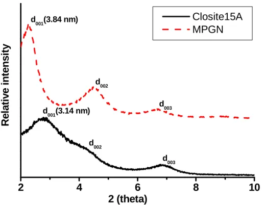
Figure 1 displays the XRD pattern of Closite 15A (aspect ratio: 75-100) and MPGN organoclay (aspect ratio: 300-500). Results show that the basal interlayer spacing of Closite 15A organoclay was 3.14nm (θ=2.8degrees) and MPGN organoclay was 3.84nm (θ=2.3degrees), suggesting that the intercalation agent increased interlayer spacing in the clay. The XRD pattern also confirms polymer effect on the organoclay intercalating behavior. Figure 2 presents XRD patterns of PETG (Sample 1) and PETG nanocomposites containing 6phr Closite 15A (Sample 4), 6phr MPGN (Sample 7), and the mixture of 3phr Closite 15A and 3phr MPGN (Sample 10). The diffraction peak of Sample 4 deviated from the original diffraction angle of 2.8 degrees to a low diffraction angle of 2.5 degrees (interlayer spacing slightly expanded to 3.53nm), indicating that polymer chains penetrated the silicate galleries. The diffraction peak of Sample 7 shifted from the original diffraction angle of 2.3 degrees to a high diffraction angle of 2.5 degrees, suggesting that polymer chains squeezed the silicate galleries and crowded the swelling agent out. [26] Nevertheless, the diffraction peak of Sample 10 obviously did not change. The TEM can further analyze the organoclay dispersion state in the PETG matrix.
Morphology
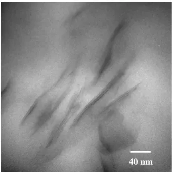
The TEM allows direct observation of the organoclay dispersion state in PETG nanocomposites. Figure 3 shows TEM photographs of the nanocomposites with 6phr Closite 15A (Sample 4), 6phr MPGN (Sample 7) and the mixture of 3phr Closite 15A and 3phr MPGN (Sample 10), respectively. All organoclay samples were well dispersed in the PETG matrix, consistent with XRD results. Figure 3 (c) clearly shows that the low aspect ratio Closite 15A organoclay was distributed in the space between the clusters of the high aspect ratio MPGN organoclay. Figure 4 furthered to show higher magnification TEM of the PETG containing 3phr Closite 15A and 3phr MPGN nanocomposites (Sample 10).
Barrier properties
organoclays on the (a) WVTR and (b) OTR properties of PETG/organoclay nanocomposites. Similar to the WVTR and OTR properties of PETG nanocomposites, the barrier properties decreased with increasing organoclay contents, indicating that more organoclay added into the polymer matrix resulted in a longer tortuous path for gas molecules to diffuse through the nanocomposite. Moreover, the barrier properties of nanocomposites containing high aspect ratio of organoclay (Sample 5, 6 and 7) were higher than those of nanocomposites containing a low aspect ratio of organoclay (Sample 2, 3 and 4). This result suggests that the organoclay with a high aspect ratio generates a more tortuous path than that with a low aspect ratio, as shown in Scheme 1(a) and (b). The barrier properties of the PETG nanocomposite (Sample 8, 9, 10) also showed synergistic effects by adding two different aspect ratios of organoclay. Sample 10 (containing 3phr Closite 15A and 3phr MPGN) showed the lowest WVTR and OTR among all samples in this study, at about 41.7% and 44.3% of those of Sample 1 (the neat PETG), respectively. This is because both the low and high aspect ratios of organoclay were dispersed in the PETG matrix (as shown in Fig 3(c)) and made a more tortuous path than those containing one single aspect ratio of organoclay at the same content (as shown in Scheme 1(c)).
Thermal Properties
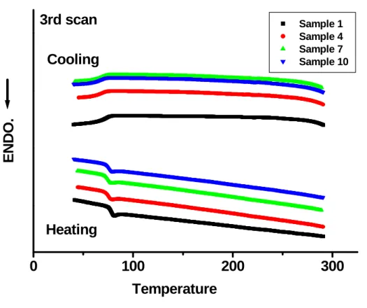
The current research studied the thermal behavior of nanocomposites during both heating and cooling at a rate of 10 oC min-1 using DSC and shown in Fig.6. Compared with the neat PETG, the Tg of the PETG nanocomposites were virtually unchanged at about 73 oC. Furthermore, PETG nanocomposites remained amorphous, revealing that introducing organoclay into the PETG hardly affected the crystallinity and did not cause nucleation effect, observed in PETG nanocomposites (Sample 4, 7, 10) and no reduced PETG nanocomposite transparency. Figure 7 presents photographs of PETG (Sample 1) and PETG nanocomposites (Sample 10) (thickness, 0.6mm). The PETG nanocomposite showed almost the same transparency as the neat PETG, even in the presence of 6phr organoclay. These results indicate that adding organoclay
into PETG improves gas barrier properties and retains transparency. Dynamic mechanical and physical properties
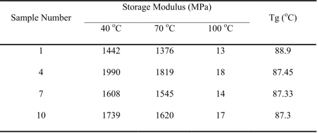
Table 2 shows the temperature dependence of the storage modulus and tangent delta of PETG and PETG nanocomposites containing 6phr organoclay 2. The nanocomposites all exhibited higher storage modulus values than that of PETG, and the enhancement appeared in different magnitudes depending on the different aspect ratios of organoclay over the entire temperature range. The nanocomposite with a low aspect ratio of organoclay (Sample 4) had the highest storage modulus, followed by Sample 10 (containing both high and low aspect ratios of organoclay) and then Sample 7 (containing a high aspect ratio of organoclay). The Tg measured by the tangent delta agreed with that measured by DSC; that is, Tg remained virtually unchanged.
Table 3 presents the physical properties of the PETG nanocomposites. The tensile modulus and strength of the nanocomposites increased with increasing the amount of organoclay. The tensile strength improved from 42.1 to 48.5 MPa. Observations showed the same behavior for the Young’s modulus s from 979 to 1107 MPa. The elongation at break and impact strength substantially declined so that the PETG nanocomposite became brittle. This is consistent with the general observation that introducing organoclay into a matrix polymer increases its strength and modulus, but reduces the elongation at break. [16, 27, 28]
Heat recovery Properties
A major PETG application is in thermal shrinkable film, therefore this study investigated the heat recovery properties of PETG nanocomposites. Figure 8 shows the heat recovery strain obtained from nanocomposites with different aspect ratios and organoclay contents. All the nanocomposites (Samples 2-10) exhibited lower heat recovery rate than those of PETG (Sample 1). The decreased heat recovery rate of the nanocomposites also coordinated with the amount of organoclay, due to adding the rigid organoclay. [29]
The current study prepared a series of PETG nanocomposites containing different aspect ratios of organoclay by the melt intercalation technique. Organoclay was dispersed in the PETG matrix with intercalation in the nanometer scale range, and did not affect the amorphous nature of PETG. The gas barrier properties of these nanocomposites increased with organoclay contents and were related to the organoclay aspect ratio due to the tortuous path effect. Observations also showed the same organoclay effects in mechanical and heat recovery properties of these nanocomposites. The experimental results suggest that tuning the gas barrier, and the mechanical and heat recovery properties of PETG nanocomposites can be exploited in designing new transparent materials for food and thermal shrinkable film applications by adjusting the type of organoclays used and organoclay contents.
REFERENCES
[1] T. J. Pinnavaia, G. W. Beall, Polymer-Clay composites. England: John Wiley & Sons Ltd, 2000.
[2] W. J. Choi, H. J. Kim, K. H. Yoon, O. H. Kwon, C. I. Hwang, J. Appl. Polym. Sci. 2006; 100(6), 4875.
[3] Z. Ke, B. Yongping, Mater. Lett. 2005; 59(27), 3348.
[4] S. H. Kim, S. C. Kim, J. Appl. Polym. Sci. 2007; 103(2), 1262.
[5] T. Wan, L. Chen, Y. C. Chua, X. Lu, J. Appl. Polym. Sci. 2004; 94(4), 1381.
[6] C. I. W. Calcagno, C. M. Mariani, S. R. Teixeira, R. S. Mauler, Polymer 2007; 48(4), 966. [7] Y. Wang, C. Shen, H. Li, Q. Li, J. Chen, J. Appl. Polym. Sci. 2004; 91(1), 308.
[8] S. L. Hsu, U. Wang, J. King; J. Jeng, Polymer 2003; 44(19), 5533.
[9] T. Tsai, C. Wen, H. Chuang, M. Lin and U. Ray, Polym. Compos. 2009; 30(11), 1552. [10] S. Wang, Y. Zhang, W. Ren, Y. Zhang and H. Lin, Polymer Testing 2005; 24(6), 766. [11] Y. H. Kim, D. S. Kim, Polym. Compos. 2009; 30(7), 926.
[12] J. M. Lee, D. S. Kim, Polym. Compos. 2007; 28(3), 325.
[13] Y, Tsai, C. H. Fan, C. Y. Hung, F. J. Tsai, J, Appl, Polym, Sci, 2008; 109(4), 2598. [14] Y. Tsai, C. Fan, C. Hung, F. Tsai, J. Appl. Polym. Sci. 2007; 104(1), 279.
[15] R. A. Kalgaonkar, J. P. .Jog, J. Macro. Sci. Part B: Phys. 2004; 43(2), 421. [16] A. Ranade, N. D’Souza, C. Thellen, J. A. Ratto, Polym. Int. 2005; 254(6), 875.
[17] T. G. Gopakumar, J. A. Lee, M. Kontopoulou, J. S. Parent, Polymer 2002; 43(20), 5483. [18] A. Ranade, K. Nayak, D. Fairbrother, N. D’Souza, Polymer 2005; 46(18), 7323.
[19] J. Zhang, D. D. Jiang, C. A. Wilkie, Thermochim Acta 2005; 430(1-2), 107. [20] R. Sayena, K. Mehrdad, Eur. Polym. J. 2007; 43(7), 2856.
[21] F. Cao, S. C. Jana, Polymer 2007; 48(13), 3790.
[23] Y. Tsai, L. Jheng, C. Hung, Polym. Degrad. Stab. 2010; 95(1), 72. [24] E. P. Giannelis, Adv. Mater. 1996; 8(1), 29.
[25] Y. Tsai, C. H. Tai, S. J. Tsai, F. J. Tsai, Eur. Polym. J. 2008; 44(2), 550. [26] H. T. Chiu, J. H. Wu, J. Appl. Polym. Sci. 2005; 98(3), 1206.
[27] J. H. Chang, S. J. Kim, Y. L. Joo, Polymer 2004; 45(3), 919.
[28] A. Sanchez-Solis, I. Romero-Ibarra, M. R. Estrada, F. Calderas, O. Manero, Polym. Eng. Sci. 2004; 44(6), 1094.
Figure Captions
Figure 1: XRD patterns of Closite 15A and MPGN organoclay.
Figure 2: XRD patterns of PETG (Sample 1) and PETG nanocomposites containing 6phr Closite 15A (Sample 4), 6phr MPGN (Sample 7), and 3 phr Closite 15A and 3phr MPGN (Sample 10).
Figure 3: TEM photographs of the PETG nanocomposites (x200,000) containing (a) 6phr Closite 15A (Sample 4), (b) 6phr MPGN (Sample 7), and (c) 3phr Closite 15A and 3phr MPGN (Sample 10).
Figure 4: TEM photographs of the PETG containing 3phr Closite 15A and 3phr MPGN (Sample 10) nanocomposites (x400,000).
Figure 5: (a) Water vapor transmission rate and (b) oxygen transmission rate of PETG and PETG nanocomposites.
Figure 6: Thermal behaviour of PETG (Sample 1) and PETG nanocomposites containing 6phr Closite 15A (Sample 4), 6phr MPGN (Sample 7), and 3 phr Closite 15A and 3phr MPGN (Sample 10).
Figure 7: The transparency of (a) neat PETG (Sample 1) and (b) PETG nanocomposite containing 3phr Closite 15A and 3phr MPGN (Sample 10).
Figure 8: Heat recovery strain of PETG and PETG nanocomposites. Table Captions
Table 1: Recipes for the preparation of PETG/organoclay nanocomposites, phr. Table 2: Dynamic mechanical properties of the PETG/organoclay nanocomposites. Table 3: The mechanical properties of PETG/organoclay nanocomposite, phr. Scheme Captions
Scheme 1: Schematic representation of tortuous path formed on the addition of the organoclay with (a) single aspect ratio, (b) mixed aspect ratio.
Table 1: Recipes for the preparation of PETG/organoclay nanocomposites, phr.
Sample Number PETG Closite15A MPGN
1 100 --- --- 2 100 1 --- 3 100 3 --- 4 100 6 --- 5 100 --- 1 6 100 --- 3 7 100 --- 6 8 100 0.5 0.5 9 100 1.5 1.5 10 100 3 3
Table 2: Dynamic mechanical properties of the PETG/organoclay nanocomposites
Sample Number
Storage Modulus (MPa)
Tg (oC) 40 oC 70 oC 100 oC 1 1442 1376 13 88.9 4 1990 1819 18 87.45 7 1608 1545 14 87.33 10 1739 1620 17 87.3
Table 3: The mechanical properties of PETG/organoclay nanocomposite, phr. Sample Number Yield strength (MPa) Tensile modulus (MPa) Elongation at break (%) Notched Izod impact (kJ/m2) 1 42.1 979 135 3.73 2 45.1 1016 102 3.39 3 46.2 1065 22 2.84 4 48.5 1107 19 1.93 5 42.9 987 121 3.34 6 43.8 1051 43 3.47 7 46.4 1059 21 3.56 8 43.2 1004 115 3.38 9 44.5 1053 30 3.36 10 47.1 1072 21 2.24
Figure 1: XRD patterns of closite 15A and MPGN organoclay.
2
4
6
8
10
d003 d002 d001(3.14 nm) d003 d002 d001(3.84 nm)R
e
la
tiv
e
in
te
n
s
ity
2 (theta)
Closite15A
MPGN
Figure 2: XRD patterns of PETG (Sample 1) and PETG nanocomposites containing 6phr closite 15A (Sample 4), 6phr MPGN (Sample 7), and 3 phr closite 15A and 3phr MPGN (Sample 10).
2
4
6
8
10
Sample 10 Sample 7 Sample 42 (theta)
Sample 1 d002 d001(3.53 nm)R
e
la
tiv
e
in
te
n
s
ity
Figure 3: TEM photographs of the PETG nanocomposites (x200,000) containing (a) 6phr closite 15A (Sample 4), (b) 6phr MPGN (Sample 7), and (c) 3phr closite 15A and 3phr MPGN (Sample 10).
Figure 4: TEM photographs of the PETG containing 3phr Closite 15A and 3phr MPGN (Sample 10) nanocomposites (x400,000).
(a) (b) (c)
100 nm
Figure 5: (a) Water vapor transmission rate and (b) oxygen transmission rate of PETG and PETG nanocomposites.
1
2
3
4
5
6
7
8
9
10
0.0
0.5
1.0
1.5
2.0
(a)
Sample Number
WV
T
R
(
mm-g
m
/m
2
-d
a
y
)
1
2
3
4
5
6
7
8
9
10
0
2
4
6
8
10
12
(b)
Sample Number
OT
R (
m
m
-c.
c.
/m
2-day)
Figure 6: Thermal behaviour of PETG (Sample 1) and PETG nanocomposites containing 6phr closite 15A (Sample 4), 6phr MPGN (Sample 7), and 3 phr closite 15A and 3phr MPGN (Sample 10).
0
100
200
300
3rd scan
Cooling
Heating
ENDO.
Temperature
Sample 1 Sample 4 Sample 7 Sample 10Figure 7: The transparency of (a) neat PETG (Sample 1) and (b) PETG nanocomposite containing 3phr closite 15A and 3phr MPGN (Sample 10).
Figure 8: Heat recovery strain of PETG and PETG nanocomposites.
1
2
3
4
5
6
7
8
9
10
0
25
50
75
100
Sample Number
Heat
r
ecov
e
ry
st
ra
in
(
%
)
Scheme 1: Schematic representation of gas molecules to diffuse through nanocomposites containing organoclay with (a) low aspect ratio, (b) high aspect ratio and (c) mixture of low and high aspect ratio.
High tortuouspath Middle tortuous path
Short tortuouspath