The Design and Realization for the Integration of Heterogeneous Networks
14
0
0
全文
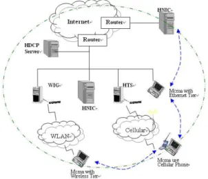
(2) independent network, its use still has some constraints. For example, the wired contact point of Internet limits the access of its resource. The integration of Internet and WLAN releases the wired constraint of contact point. Internet, PSTN, Cellular Network and WLAN are four popular networks. They all have their own features and applications. From the user’s viewpoint, to have an environment, which transmits the information (voice, data, video, etc.) between their terminal devices, is appreciated. Therefore, how to integrate these networks and to provide the ability of communication between each network is new challenge. Figure 1 shows the concept of the network integration. Due to the communication protocol used, the internetworking, interoperation [6][7][8], and mobility management [9][10][11] should be solved, if figure 1 will be realized. In the future, to rely on the integration network, the protocols can coordinate each other, the applications of networks can be shared, and the features of original network can be reserve. As figure 1 shown, each network can communicate with each other by the Integration and the applications of Data, Voice, and Video can be shared.. Due to the diverse development of communication techniques, to integrate different networks for uniform operation is important for users. There are many researches aimed at this purpose. The IMT 2000 [] and All IP [] network are two popular ones. IMT 2000 proposed the architecture for the integration of the networks; the integrated environment is transparent to the user of individual network. Figure 2 shows the framework of All IP network. Its goal is to build an IP based communication environment for the integrated network. The integrated existing network poses its original features. The communication of terminal devices should be via the IP based core network. Therefore, the design of gateway and network management becomes important. It will decide the features of the integrated environment. The related technique under All IP network includes SoftSwitch [13][14], GPRS/3G Core Network, OSA Gateway, High Through-put Media Gateway, Media Server, Voice over Packet Processor., and the writing of applications.. Figure 1 the concept of network integration. Figure 2 the framework of All IP network. The goal of our study is to propose a framework for the integration of networks, so that the work of network integration becomes easier. Internet, Cellular phone system, PSTN, and Wireless Local Area Network are more popular, so the integration of these four networks is taken as an example in implementation. The new integration environment should have the following properties: (1) it is a network, not many networks for users; (2) the new and old applications can coexist in the integration network; (3) A seamless roaming environment is easily built; (4) ALL-IP network; (5) Flexibility in using adapter to recover a device fault.. SoftSwitch is an encompassing term for next generation communication system. It employs the open standard to create integrated networks, which is able to carry voice, video, and data efficiently. It also emphasizes the building of personal intelligent services on the integrated network for users. It is an important component in the future, if a multimode communication model is required. The functions of SoftSwitch given by industry are followed: ¾ Support existing traditional interfaces and services in addition to new interfaces and services. ¾ Support voice, video, and data services. ¾ Provide an interface for remote service control through standard interfaces, such as. 2. Related Study. 2.
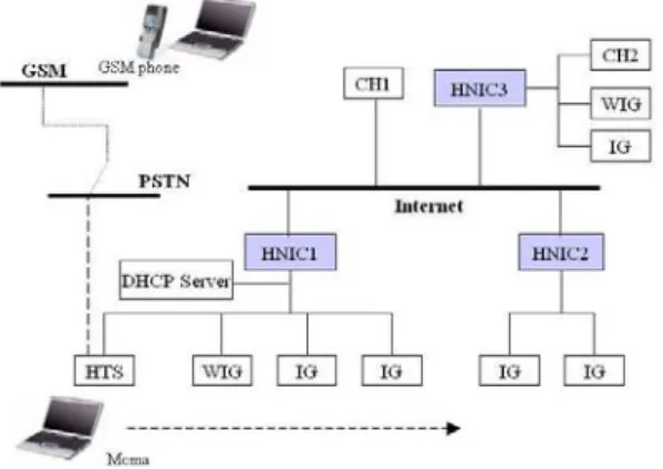
(3) bridge between Internet and other networks. The second layer is called IG (Interface Gateway), which is an interface for a special network to connect to Internet. The IG for a cellular network is called HTS (High Tier Server); that for WLAN is called WIG. The third layer is the terminal device, which is called Mcma (Mobile Host with Multiple Adapter). Mcma is a client of the integrated environment. The service area of a HNIC is called domain. In each domain, there is a DHCP server for dynamic assigning an IP address to a Mcma.. IN-based Service Control Points (SCPs), Parlay-based Parlay servers, JAIN servers, and SIP-based SIP Application servers. All these interfaces should provide in parallel, so that some services are supported locally; while other services are being provided through different servers. ¾ Support distributed control, signaling, services, and media (connection) planes. ¾ Support next generation mobile networks, like 3G-based mobile networks.. Figure 3 an example of multi-access integrated networks To implement an All IP Network is not easy. Figure 3 shows an example of an All IP network [15] [16]. It integrates many networks, which include PSTN, Internet, WLAN, 2G/3G cellular system, new radio network and low coverage radio system, etc. Its realization is dependent on the availability of the border gateway, i.e., the component, which connects the network to IP based backbone. The success of Figure 3 depends on its quality, performance, friendly interface, flexibility, roaming ability, efficiency of transmission, etc. 3.. Figure 4 The Physical Architecture of the Integrated Network The goal of the integration is to provide users the ability to get information on Internet everywhere and anywhere. Due to the coverage area and the bandwidth of tiers, a mobile host with multiple tiers is needed if that host will roam over the integrated environment. The other goal of the designed system is that each integrated network should pose its original features.. The Designed System. In this section, the implemented system is described. The description is divided into 3 parts: physical architecture, logical architecture, and design issues.. 3.2 Logical Architecture Figure 5 is the logical architecture of the system. HNIC is the center of the system. It serves as an intelligent border gateway. The information, which is exchanged between terminal devices and the servers on Internet, should be via HNIC. The service area of the IGs managed by a HNIC forms a domain. A Mcma may roam over the integrated environment. The roaming of a Mcma within a domain is called local roaming; that of a Mcma across the boundary of a domain is called global roaming. The DHCP server is in. 3.1 Physical Architecture Figure 4 is the physical architecture of the integrated networks, which includes three networks, Internet: Internet, WLAN, and Cellular Network. Internet is the backbone for the integration. The elements of integration modules are arranged into three layers. The first layer is HNIC (Heterogeneous Network Integration Center), which is designed as a 3.
(4) (3) Seamless Roaming The greatest benefit of integrating a wireless network into a fixed one is that the mobile ability of the wireless device can be extended to the integrated network. Although MIP provides the mechanism for roaming, but there are still many constraints if seamless roaming is needed. For example, the roaming at the position, where no wireless adapter is available, will be ceased. Due to the respective feature and the availability of tiers (adapter), to build a seamless roaming environment over Internet with a single tier is not practical. Therefore, how to use the unique feature of each tier and complement their usage become important and necessary. (4) Local Roaming It is the roaming within the area covered by IGs, which are monitored by a single HNIC. The range of local roaming depends on the distribution of the IGs. It can be in a school campus or a building. The roaming is at pedestrian speed, and usually is indoor roaming. Our design is more emphasized on this kind of roaming; therefore, its performance should be good. (5) Global Roaming It is the roaming across the boundary of the area controlled by an HNIC. We will support it to complete the capability of roaming, so that a mobile terminal device can access the resource on Internet everywhere and anywhere. Triangle routine cannot avoid, if transparency is considered the most important. We will pay more attention to the improvement of this defect. (6) Flexibility in using adapters Due to the special feature, e.g., the availability, the coverage range, the bandwidth, etc., of each tier and the cost of transmission, to provide the flexibility of using tiers is important in the future, especially, if a real seamless roaming is needed. In this paper, the uses of the adapter of Ethernet, Cellular, and WLAN are discussed. (7) Transparency It is the most important factor that should be considered, if new applications want to coexist with the old one. For this purpose, the network address translation technique is employed in designing HNIC. With the help of HNIC, Mcma can access the resource of any computer outside its control area. The. charge of dynamically assigning an IP address to a moving Mcma. HNIC provides the common function for roaming. IG is responsible for connection of HNIC and terminal devices. The design of IG is kept as simple as possible, so that the integration of individual network becomes easier.. Figure 5 The Logic Architecture of the System CH is a host on Internet. It is the server that a terminal device will communicate with. The function of HNIC and IG is to keep the communication between Mcma and CH will continue even Mcma is in moving. 3.3 Design Issues In this section, we will describe the factors what are concerned when the system is designed. The factors are as follows: (1) Toward standardization Standardization is very important in communication software. The SIP, MGCP, and MeGaCo are the talking standard for the next generation telephony technologies. Our design will follow these standards and provide more complete mobility and roaming ability. The standardization module will compatible with next general network architecture and enhance the expandability. (2) All IP environment The concept of All-IP network is the trend in the future. The concept is that each terminal device should have an IP address for identification. Figure 1 is a framework of All IP network. The core network is IP based. The exchange of the information is via the core network. The individual network will connect to the core with a gateway interface. This kind of connection would reduce the cost and complexity of integration. 4.
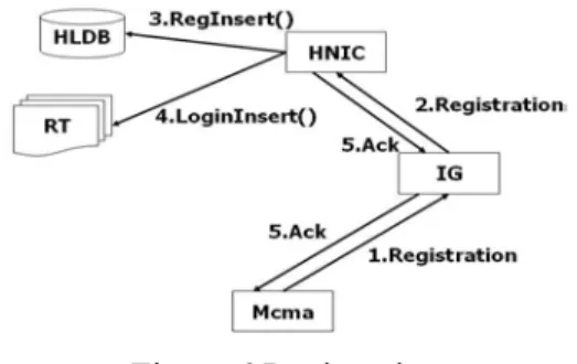
(5) Mcma is located, at Home Location Database in HNIC. If the registration is initial one, the address of HNIC is that of home HNIC of the requested Mcma. The registration process would also record the McmaPN and current IP address of requested Mcma at Redirect Table of its visiting HNIC; then the Mcma could connect or accept a connection request; Mcma should send an “alive” message to its visiting HNIC in a fixed period to announce that he is still alive, otherwise, the visiting HNIC of a Mcma would delete the location information of this Mcma.. accessed computer doesn’t necessarily aware the location of the accessing computer, i.e., the server on Internet need not do any modification in the new environment. All the modification is done on HNIC. The problem of triangle transmission is already reformed, the performance of global roaming and communication services would be better and also the transparency. (8) Programmable and application impendent The function provided by HNIC should be independent to applications or protocol. HNIC will provide the primitive mechanism, not the protocol, for roaming. Users can have their own protocol for their special purpose. If the primitive function is not enough for a special application, users can add new function to HNIC through the function provided by HNIC. (9) Identifier Each Mcma in this environment needs a unique name to identify itself. But the identification method is not always the same in different applications, e.g., an IP address is used to identify a computer on Internet; a number is used on PSTN or GSM. In our design, a two level naming method is used. A global unique name is employed in the first level, which is managed by HNIC; the second level is open to the application. When an application needs its own name, the developer should map his name into this global unique name, so that the current location of a Mcma can be found. For example, the ITG for VoIP application should map the number of a Mcma to a unique name. 4.. Figure 6 Registration The process of initial registration includes to ask for a name and to update the location information. The protocol is described in the following: (See Figure 6) (1) Mcma sends a Registration request with its McmaPN and its current IP address to the source of the beacon received. (2) IG transmits the request to HNIC, if needed. (3) After receiving the request, HNIC would determine if it is an initial registration or a handoff. ¾If it is an initial registration, then call a RegInsert() with Mcma NickName; the nicknamewill is checked; if it is already used, HNIC would send a failure Ack back to Mcma; if not, the McmaPN and the IP address of its visiting HNIC are recorded; then goto step (4). ¾If the Mcma already have a McmaPN, it just need to update the location information; then goto step (4). (4) HNIC would get the IP address of command source to be the Mcma Destination IP, this IP may be the Mcma current IP address or the IG IP address that link with this Mcma. Then, prepare to update the location information: ¾If the HNIC is the Home HNIC of Mcma: I. Call CHUpdate() function with HNICIP parameter to update the Current HNIC IP address at Home Location Database II. Call LogInsert() function with McmaPN. System Operation Model. 4.1 Registration Each Mcma should ask for a name before communication, which is called Permanent Name (McmaPN); it is a global unique name for the identification of a Mcma in the system. User can create a nickname by himself and send it to his home HNIC for registration. The system naming is McmaNickName@HomeHNIC_IP for Mcma, e.g., [email protected] is a name for a Mcma. CH_IP#HNIC_IP is for a CH, e.g., 140.16.39.53#140.116.39.67 is a name for a CH. When the registration successes, HNIC would send this Permanent Name to user, and record this McmaPN and IP Address of HNIC, where 5.
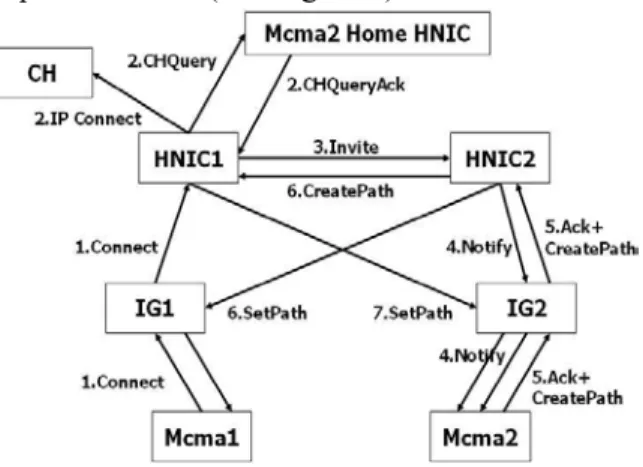
(6) (1) Mcma move to the control area of the other HNIC and received the beacon; (2) Mcma send the Registration/Handoff command to the Visit HNIC directly or transmit by IG2 include the McmaPN and its current IP address; (3) When Visit HNIC received the Registration/Handoff command: I. Record the McmaPN and Mcma current IP Address at Redirect Table, its use for Location Tracking; II. Determine the Home HNIC IP Address of Mcma by McmaPN and send the CHUpdate command with Visit HNIC IP Address parameter to Mcma Home HNIC; If this Visit HNIC is the Mcma Home HNIC, it would update the Mcma Current HNIC IP Address to be the self IP address at Home Location Database. III. If the command is Handoff, Visit HNIC should to rebuild the connection, if not, finished the processes. (4) Home HNIC received the CHUpdate command and to update the Mcma Current HNIC IP Address to be the Visit HNIC IP address at Home Location Database.. and Destination IP address parameters and to add this location information at Redirect Table。 ¾If not: Send the CHUpdate command to the Mcma Home HNIC with this HNIC IP address; (5) Send the registration success Ack back to the Mcma, finished the registration process. Mcma could start communication after finishing the registration. When the Mcma move to another place, it must register to the HNIC at that domain to update its location; If the Mcma is moving when communication, it must send the Handoff command to the HNIC to reestablish the route path. 4.2 Handoff When the Mcma move to the area of another HNIC controlled or switch the other network adapter, system will execute the Handoff process to update the location and establish the data path for keeping the former communication. There have two types of Handoff : Horizontal Handoff and Vertical Handoff. When the Mcma move to another environment and do not need to change the network adapter to keep online, this situation was called Horizontal Handoff, if need to change the network adapter was called Vertical Handoff. But no regardless of Horizontal handoff or Vertical Handoff, the processes in the system were consistency, system just according to the location information that Mcma sand in the Handoff command to reestablish the packets transmit path, the Mcma do not need to know about which kind of Horizontal handoff or Vertical Handoff, all the jobs Mcma need to do is send the current IP address to the system, the functions system provided would handle the routing problem after roaming, and also provide the transparency to Mcma when roaming. Figure 7 illustrate the processes of Handoff and list the steps below:. 4.3 Location Tracking & Connect In our design system, the Mcma could communication with the other Mcma or the host in Internet and the protocol model of both were the same. Every time Mcma want to communication with the other, it must search the location of the target by system and then set the connection to it. These steps were called Location Tracking or System Signal Path. The steps of location tracking and connect were explain below:(See Figure 8). Figure 8 Location Tracking & Connect. Figure 7 Handoff. (1) Mcma1send the Connect command to 6.
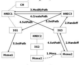
(7) command, those would change the state to Busy and record the name of communication target, and then send the success Ack back to HNIC that send the SetPath command. Finished the Connect steps. The data path is: ¾ Mcma1 Æ IG1 Æ HNIC2 Æ IG2 Æ Mcma2 ¾ Mcma2 Æ IG2 Æ HNIC1 Æ IG1 Æ Mcma1 ¾ Mcma1ÅÆIG1ÅÆHNIC1ÅÆCH If the Mcma use the Ethernet adapter, the data path would not pass through IG and direct to HNIC.. HNIC1 directly or transmit by IG1; (2) After HNIC1 received the Connect command, it would determine the communication target is Mcma or CH by its name with the “@” mark inside or not, if yes, the target is Mcma, if not, it is CH: ¾The target is Mcma:query the Mcma2 if under the control of HNIC1: 9 Yes, find out of its current IP Address and send the connection notify. Finished the Location Tracking; 9 No, HNIC1 send the query Mcma2 Current HNIC IP address request to the Mcma2 Home HNIC, HNIC2 would send the IP address of Mcma2 Current HNIC2 IP address back to HNIC1;if the field of Mcma2 current HNIC IP address at Mcma Home HNIC is empty, it means that the Mcma2 was offline, then send the failure Ack back to Mcma1; ¾The target is CH:HNIC1 connect to the CH directly use the CH IP address. Finished the Location Tracking and Connect. (3) After HNIC1 got the Mcma2 current HNIC3 IP address from Mcma2 Home HNIC, it would send the invite command to HNIC2; (4) After HNIC2 received the invite command, it would find out the Mcma2 Destination IP address from the Redirect Table according to Mcma2PN within the invite command, and then send the connect Notify to Mcma2 directly or transmit by IG2. Finished the Location Tracking. (5) After Mcma2 received the Notify command, if Mcma2 is on communication or do not accept the connect request, Mcma2 would send the failure Ack with the system message back to Mcma1;if Mcma2 accept the connect request, it would send the success Ack and CreatePath command to HNIC2 directly or transmit by IG2 to notify the HNIC2 set the connection to Mcma1; (6) After HNIC2 received the CreatePath command, it would send the CreatePath command to HNIC1 with Mcma2 IP and send the SetPath command to Mcma1 directly or transmit by IG1 to establish the connection; (7) After HNIC1 received the CreatePath command, it would send the SetPath command to Mcma2 directly or transmit by IG2 to establish the connection; (8) After both Mcma received the SetPath. 4.4 Roaming Due to the Mcma have the move ability and the situation that roaming on communication was take often, if there have not the suitable roaming functions, it would cause the communication interrupt and lost large packets, it just can say that the Mcma have no roaming ability. If roaming success and reestablished the route path, many systems have the triangle routing problem, it would reduce the performance;we improve our system aimed at roaming and transmission path to provide the effective operation model, there would describe the roaming protocol include the target is Mcma and CH below:(See Figure 9). Figure 9 Roaming (1) Mcma2 move to the control area of HNIC3 and received the new beacon; (2) Mcma2 send the Handoff command with Mcma1PN and HNIC1IP to the HNIC3 directly or transmit by IG3; (3) HNIC3 received the Handoff command and determine the communication target is the other Mcma or CH according to its name, 7.
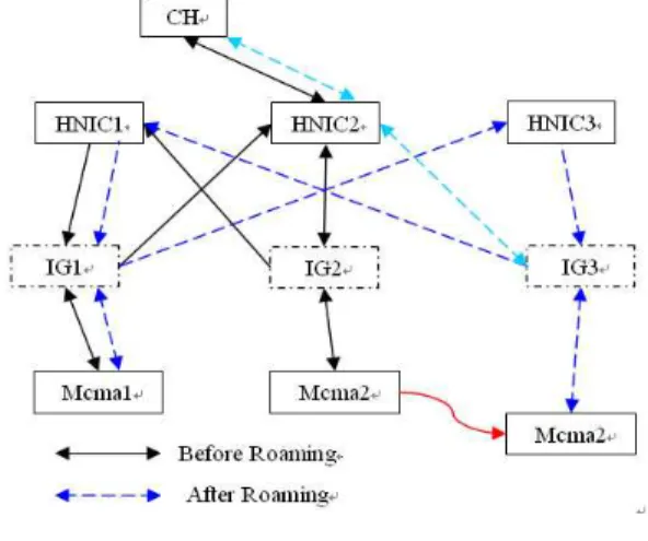
(8) ¾ If the target is CH, steps(4)(5)(6) ¾ If the target is Mcma, steps(7)(8)(9)(10) (4) HNIC3 received the Handoff command and to know the CH was connect with HNIC1 according to CH system name and then send the ModifyPath command with the new Mcma2 Destination IP address; (5) HNIC1 received the ModifyPath command and then disconnect the former connection, then, send the SetPath command to Mcma2 directly or transmit by IG3. Mcma2 IP was within the ModifyPath command; (6) Mcma2 received the SetPath command and send the success Ack back. Finished the roaming and keeping the former communication. The data path after roaming is: ¾ CH ÅÆ HNIC1 ÅÆ IG3 ÅÆ Mcma2. 4.5 Data transmission and recovery In the field of mobility, the data transmit path of many systems would become complex after roaming, it may take up the network bandwidth and have worse performance and even lost the packets easily. To consider these shortcomings, it’s important to improve the data path after roaming. In our design system, the data path model before and after roaming was the same no matter communication with Mcma or CH. This way would enhance the performance of data transmission and recover. The IG was design to link with each heterogeneous network, so the data path may pass through it unavoidable, but the IG could to be the role of an agent or access point, if the Mcma uses the Ethernet adapter connect to the system, the data path would not pass through the IG. The every path is just passing through one HNIC and the reason that passes through HNIC is to store the packets use for packets recover.. (7) HNIC3 received the Handoff command and send the ModifyPath command with the new Mcma2 Destination IP address to HNIC1 that within the Handoff command; (8) HNIC1 received the ModifyPath command and then disconnect the former connection, and send the CreatePath command with Mcma1 Destination IP address to HNIC3; Then, send the SetPath command to Mcma2 directly or transmit by IG3. Mcma2 IP was within the ModifyPath command; (9) HNIC3 received the CreatePath command with Mcma1 Destination IP Address and then send the SetPath command to Mcma1 directly or transmit by IG1; (10) After both Mcma received the SetPath command, those would send the success Ack back to HNIC that send the SetPath command. Finished the Roaming steps and keeping the former communication. The data path after roaming is: ¾ Mcma1 Æ IG1 Æ HNIC3 Æ IG3 Æ Mcma2 ¾ Mcma2 Æ IG3 Æ HNIC1 Æ IG1 Æ Mcma1 If the Mcma use the Ethernet adapter, the data path would not pass through IG and direct to HNIC. To compare the data path before and after roaming, we can see the data path model was the same. The system policy of roaming and reestablished the route path was improve the problem of triangle routing.. Figure 10 Data Path See the Figure 10, it’s the data path of our system: Before Roaming:(Thick lines) Mcma1 Æ Mcma2: Mcma1ÆIG1ÆHNIC2ÆIG2ÆMcma2 Mcma2 Æ Mcma1: Mcma2ÆIG2ÆHNIC1ÆIG1ÆMcma1 Mcma2 & CH: Mcma2ÅÆIG2ÅÆHNIC2ÅÆCH After Roaming:(Dotted lines) Mcma1 Æ Mcma2: Mcma1ÆIG1ÆHNIC3ÆIG3ÆMcma2 Mcma2 Æ Mcma1: Mcma2ÆIG3ÆHNIC1ÆIG1ÆMcma1 Mcma2 & CH: Mcma2ÅÆIG3ÅÆHNIC2ÅÆCH 8.
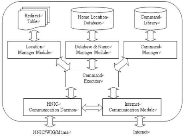
(9) (2) HNIC receiver the Bye command and determine the HNIC is the Home HNIC of Mcma or not: I. Yes, call CHDelete function with McmaPN parameter and to find out and clean the field of Mcma Current HNIC; II. No, HNIC send the CHDelete command with McmaPN to the Mcma Home HNIC; (3) HNIC finished the Bye process and then send the success Ack back to Mcma.. We can see the data path that describe above, the path model is sender (Mcma or CH) send the packets to the HNIC of receiver (Mcma or CH) directly or transmit by IG and then this HNIC transmit to the receiver (Mcma or CH) directly or transmit by IG. The data path model was consistency whatever how many the times Mcma roaming, this model was suitable for all kind of communication targets and also improve the problem of triangle routing. This model was also considered about the packets recover. See the Figure 11.. 5. The Design of System Module 5.1 HNIC The goal of HNIC is to provide the common function for integration and mobility support for constructing a seamless and transparency roaming environment. Its function includes providing a set of control signal, which is compatible with that of Internet, managing the Mcma, in charge of location tracking and connecting the corresponding host for the Mcma when it is roaming, reestablishing the data path and retransmit the loss packets. The Figure 13 is its software architecture.. Figure 11 Packets Recover When it’s need to execute the packets recover process, it just need to request the packets recover form former HNIC, the distance of packets recover would be shorter than request to the HNIC of sender, because the HNIC that before and after roaming would be neighbor, it’s obvious in the local roaming case, the Mcma just send the request to the same HNIC, the data path of recover is shortest. 4.6 Offline When the communication finished, Mcma should logout of the system. The system would clean the Mcma Current HNIC field at Home Location Database. If other Mcma want to communication with this Mcma, the system would find out this Mcma is not on the system, i.e., offline. The step is listed below:. Figure 13 HNIC Software Architecture The function of each component is described below: (1) HNIC Communication Daemon The HNIC communication daemon is always to be in monitor; it would receive or forward the packet from IG or other HNIC, and handle the action of registration and handoff. It is like the gate of Internet. (2) Internet Communication Module The Internet communication daemon is in charge of encapsulation and deencapsulation of packets, it would decapsulate the system packets to be the standard TCP/IP packets and send to. Figure 12 Offline Protocol (1) Mcma send the Bye command to the current HNIC directly or transmit by IG; 9.
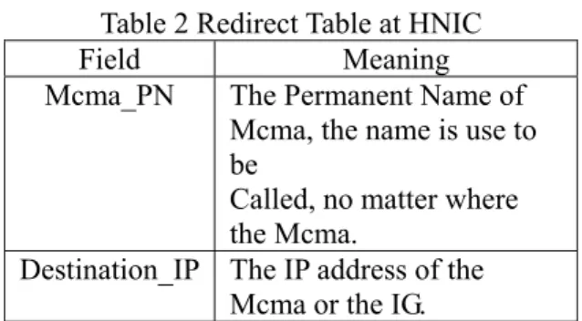
(10) the Internet, it would also encapsulate the TCP/IP packets to be the system packets and transmit the packets to the system command executor. (3) Command Executor This component is the core component in HNIC. Command Executor receives the command and data from HNIC Communication Daemon or Internet Communication Module, and interprets the command, then calls the corresponding function provides by other component (Name & Database Manager Module and Location Manager Module, Internet Communication Module) and to acquire relative information from database to execute. Besides, it can send command and data to Internet or IG and other HNIC through HNIC Communication Daemon or Internet Communication Module. (4) Location Manager Module The main function of this module was record 、 search or delete the Mcma location information in the Redirect Table. It would be refer when the communication and it would find out the destination IP address of Mcma by McmaPN. (5) Database & Name Manager Module The main function of this module was adding a McmaPN and maintains the current HNIC of Mcma at the Home Location Database. It would be refer when the communication and it would find out the current HNIC IP address of Mcma by McmaPN. (6) Command Manager This component allows user to add his commands at the command library into the system according to his requirement. (7) Database and Table The system must to design the database and table to record the location information for connect request and reestablished the data path after roaming. There have three recorder in HNIC, the data structure and contents were describe below: A. Home Location Database. This database is at HNIC, it is the home register of the Mcma, and it records the McmaPN and the current HNIC IP address of this Mcma; if there has someone want to call the Mcma, HNIC would query the current HNIC IP address of this Mcma. The database is permanence; it would not affect the contents of this database even HNIC was broken or shut down. B. Command Library Every HNIC was having this library, it stored the new functions by Command Manager, and HNIC would have more powerful services. C. Redirect Table Table 2 Redirect Table at HNIC Field Meaning Mcma_PN The Permanent Name of Mcma, the name is use to be Called, no matter where the Mcma. Destination_IP The IP address of the Mcma or the IG. This table is at HNIC, it is the visit register of the Mcma, and record the McmaPN and Mcma Destination IP address, the destination IP address may be the Mcma current IP address or the IG IP address which connect with Mcma when Mcma use specific adapter; when the other one want to connect with Mcma, HNIC would query the Redirect Table to find out the destination IP address of Mcma at present, than redirect the packets to this Mcma. 5.2 Intelligent Gateway The goal of design IG is to link with Mcma into Internet and expand the move ability of Mcma. The specific IG link with the Mcma with specific adapter and manage Mcma by applicable module. We want to make the IG simply and it would integrate the other network easily. The Figure 14 is the IG software architecture:. Table 1 Home Location Database at HNIC Field Meaning Mcma_PN The Permanent Name of Mcma, the name is use to be Called, no matter where the Mcma. Mcma_CHNIC The current HNIC of Mcma. Reserve Other information for authentication 10.
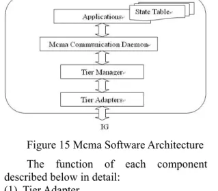
(11) It records the McmaPN and its wireless IP address. A Wireless IG would find the wireless IP address of a Mcma by McmaPN, then forward the message to it through wireless network. 5.3 The Mobile Computer In order to fully use the feature of the integrated environment, the mobile computer should be installed with more than one kind of network adapters. It is called Mcma. The Figure 15 is its architecture. Figure 14 IG Software Architecture To describe the function of each component in detail below: (1) Tier Adapters It is the physical interface of IG that provides communication between IGs and other subsystem like Mcma and HNIC. All information of IG will be received or transmitted through certain ADAPTER like Wireless LAN card or Ethernet card. (2) Tier Manager It manages the operation of all the adapters that IG owns and records the relative information. It is also responsible for the switch of adapters especially during a session of communication. (3) IG Communication Daemon It will transfer the received packets to the appropriate component of IG. It is the critical component that controls everything happening in IG. (4) Agent Manager It is responsible for the creation and the deletion of agents, and manages all the operations of agents. (5) Agent When Mcma registers to HNIC through IG, IG will activate an agent for Mcma. Every agent is designed for specific protocol like Mobile IP. During the session of communication, the agent will control the operations and record the information for served Mcma. (6) Mapping Table. Figure 15 Mcma Software Architecture The function of each component is described below in detail: (1) Tier Adapter It is the driver of hardware adapter, such as Wireless LAN card or Ethernet card. (2) Tier Manager It manages the operations of adapters that Mcma owns. It also provides has the policies for vertical handoff policy. (3) Mcma Communication Daemon It will deal with all the requests from users and all the operations from the system. It is the key component to provide the transparency to users. System can control the operations of Mcma and provide better communication quality by the component. (4) Application The system will offer an adequate environment for users to run the application. And the system will offer the customized operations user desire by setting the parameters in the sent packets. When Mcma communication Daemon receives the request by detecting the parameters, it will do the appropriate operations according to the parameters. (5) State Table. Table 3 Mapping Table at Wireless IG Field Meaning Mcma_PN The Permanent Name of Mcma, It is used to be Called, no matter where the Mcma. Mcma_Wirele The wireless IP-address of ss_IP Mcma when it used Wireless Adapter.. Table 4 State Table at Mcma Field Meaning Corresponding The Permanent Name or IP of 11.
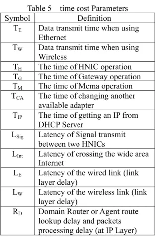
(12) _Host State. TReg(W) = 2(TM+TW+TG +TE )+TH Table 6 lists the data of the result, which is measured, repeatedly. The cost of registration of Mcma, which uses wireless adapter, is more than that uses Ethernet adapter. This is due to the registration through wireless adapter take two additional paths, i.e., 2*(TW+TG). This cost is 2TW+2TG = 180ms. The result is the same as our measurement.. a corresponding host. 0:Mcma is active, but ready for communication. 1:Mcma is active, but busy now.. This table is at Mcma, it record the state of communication of Mcma, the State field showed that the Mcma is on communication or just is normal registration, if the Mcma is on communication now, the table would record the name of communication target and change the state to be Busy.. Table 6 the cost of Registration process Unit: ms Ethernet Wireless Average Registration. 60. 240. 150. 6. Performance Handoff (E: Ethernet; W: Wireless) When the Mcma communicates with CH, there are various situations of handoff. The notation used in analysis is as follows: L: means Local Handoff. G: means Global Handoff. V: means Vertical Handoff H: means Horizontal Handoff A⇒B: means that Mcma change from the adapter A to adapter B. For example, TLVEW means the total cost of Mcma, which executes a Local Vertical Handoff and changes from Ethernet adapter to Wireless adapter. The cost is as followed:. A prototype is built in our laboratory. It seems function well. The performance test is aimed at the cost of handoff and registration. Table 5 is the symbol used in the analysis. Table 5 time cost Parameters Symbol Definition TE Data transmit time when using Ethernet TW Data transmit time when using Wireless TH The time of HNIC operation TG The time of Gateway operation TM The time of Mcma operation TCA The time of changing another available adapter TIP The time of getting an IP from DHCP Server LSig Latency of Signal transmit between two HNICs LInt Latency of crossing the wide area Internet LE Latency of the wired link (link layer delay) LW Latency of the wireless link (link layer delay) RD Domain Router or Agent route lookup delay and packets processing delay (at IP Layer). TLVE⇒W=LE+TCA+LW+2(TM+TW+TG+TE) +TH TLVW⇒E=LW+TCA+TIP+LE+2(TM+TE)+TH TLHW⇒W=2LW+2(TM+TW+TG+TE)+TH TGVE ⇒ W =LE +TCA +LW +2(TM +TW +TG)+ 5TE+2TH+4RD+2LInt TGVW ⇒ E = LW + TCA + TIP + LE + 2TM + 5TE + 2TH+4RD+2LInt TGHE ⇒ E =2LE +TIP +2TM +5TE +2TH +4RD + 2LInt TGHW ⇒ W =2LW +2(TM +TW +TG)+5TE +2TH +4RD+2LInt We can find the cost of transmitting a signal between two HNICs is fixed, which is the sum of several parameters, in Global Handoff. We use LSig to represent it.. Registration We can list the total cost of registration in different situation according to the definition above: TReg(E) means the cost of registration of Mcma that use Ethernet Adapter, TReg(W) means the cost of registration of Mcma that use Wireless Adapter. TReg(E) = 2(TM+TE )+TH 12.
(13) faster adapter (TCA) can be used; the getting and setting of an IP address (TIP) should be faster; and the system module should be optimized. 7. Conclusion and the Future Work The environment of next generation will be an integrated network; the users could use the terminals, which connect to the network through standard interfaces. The core network will provide various kinds of services and handle all the communication behavior. Our system is designed toward this aspect. The goal of our design is to provide a framework for integration and to construct a seamless roaming environment for the integrated environment. We bring up the solutions for constructing seamless roaming environment with multiple tiers. It should solve the problem of horizontal handoff, and vertical handoff, simultaneously. In summary, it is not easy to build a prototype for testing. Through our work, we have the following results: 1. Three-layer architecture provides a flexible framework for network integration. We successfully integrate three kinds of networks: Internet, Wireless LAN, and GSM. 2. The use of HNIC makes the construction of a seamless roaming environment become easier. 3. The operation of integrating the multiple tiers makes the recovery of the defect of a tier on line become feasible. In the future works, we will aim at some aspects to discuss: 1. To optimize the system modules. 2. Improving the effective of transmission. 3. To provide the API (Application Program Interface) for new application development. 4. To provide the function of QoS. 5. To provide the service of multimedia; 6. To meet the industry standard.. Figure 16 the cost of each path By figure 16, LSig=TE+RD+LInt+RD+TE=2(TE+RD)+LInt For easy in analysis, the above formula can be simplified to: TGVE ⇒ W=LE +TCA +LW+2(TM+TW+TG +TH +LSig)+TE TGVW⇒E=LW+TCA+TIP+LE+2(TM+TH+LSig) +TE TGHE⇒E=2LE+TIP+2(TM+TH+LSig)+TE TGHW ⇒ W = 2LW + 2(TM + TW + TG + TH + LSig)+TE Table 7 lists the data of the result, which are measured, repeatedly. Mcma could connect with HNIC directly when using Ethernet adapter. It does not have Ethernet Adapter Handoff in Local Handoff. Table 7 the cost of handoff process Unit: ms Vertical Horizontal Average Handoff E⇒ W⇒ E⇒E W⇒W W E Local 240 190 270 × Global. 390. 320. 280. 410. 300 240 355. By table 7, We can see that the cost difference of changing adapter from either Ethernet or Wireless adapter to Wireless adapter is “LE+TCA+20ms=LW”, no matter Local or Global Handoff is executed. It is thus clear that the cost of connecting and disconnecting link layer in wireless is much more than that in wired. Comparing the cost of Local and Global Handoff, the delay (i.e., LSig) of transmit signal between HNICs spend much time. The delay of routing from one domain to another domain is complex and hard to count. It depends on the situation of the network at that time. In Global Handoff, there is additional cost TH (Due to one more HNIC in co-operation). Therefore, the cost of Global Handoff is more “2LSig +TH -TE” more than that of Local Handoff. It is about 140ms. In order to improve the performance, a. Reference [1] J. B. Postel, ed.; “Internet Protocol”, RFC 791, Sept. 1981 [2] Lee, T.H., Samavati, H., Rategh, H.R.; “5-GHz CMOS wireless LANs”, Microwave Theory and Techniques, IEEE Transactions on , Volume: 50 Issue: 1 Part: 2 , Jan. 2002. [3] Qi Bi, Zysman, G.L., Menkes H.; “Wireless mobile communications at the start of the 21st century”, IEEE Communications 13.
(14) UMTS/IMT-2000 evolution”, Electronics & Communication Engineering Journal, June 2000. [17] Barani Subbiah and Yrjo Raivio; “Transport architecture evolution in UMTS/IMT-2000 cellular networks”, 3Com Corp. and Nokia Networks, May 2000.. Magazine, Volume: 39 Issue: 1, Jan. 2001. [4] Yile Guo, Antoniou, Z., Dixit, S.; “IP transport in 3G radio access networks:an MPLS-based approach”, Wireless Communications and Networking Conference, 2002. WCNC2002. 2002 IEEE. [5] Moritz P.; “Conveying IN into an All-IP network's service architecture”, Intelligent Network Workshop, 2000. Proceedings. 2000 IEEE , 2000 [6] Wolfgang Kellerer1, Hans-Jorg Vogel2, and Karl-Ernst Steinberg3; “A Communication Gateway for Infrastructure-Independent 4G Wireless Access”, 1Technische Universitat Munchen, 2Fantastic Corp., 3BMW, IEEE Communication Magazine, Mar. 2002. [7] Gyasi-Agyei, A.; “Mobile IP-DECT internetworking architecture supporting IMT-2000 applications”, IEEE Network, Volume: 15 Issue: 6, Nov.-Dec. 2001. [8] Huston, G.; “TCP in a wireless world”, IEEE Internet Computing, Volume: 5 Issue: 2, March-April 2001. [9] Verkama, M.; Soderbacka, L.; Laatu, J.; “Mobility Management in the Third Generation Mobile Network “Global Telecommunications Conference, 1996. GLOBECOM '96. 'Communications: The Key to Global Prosperity, Volume: 3, 1996 Page(s): 2058 –2062 vol.3. [10] Ian F.Akyildiz, Janise McNair, Joseph Ho, Huseyin Uzunalioglu, and Wenye Wang; “Mobility Management in Current and Future Communications Networks, IEEE Network, July 1998. [11] Akyildiz, I.F.; McNair, J.; Ho, J.S.M.; Uzunalioglu, H.; Wenye Wang; “Mobility Management in Next-Generation Wireless Systems” Proceedings of the IEEE, Volume: 87 Issue: 8, Aug. 1999 Page(s): 1347 –1384. [12] Lee, D.J.Y.; Lee, W.C.Y.; “Mobile IP/sup 2/”, Communications, Computers and signal Processing, 2001. PACRIM. 2001 IEEE Pacific Rim Conference on, 2001. [13] _____; “Routing Solution for the Next Generation Network Based on SoftSwitch”, ZTE Technology, www.zte.com.cn. [14] _____; “Challenges for Building Softswitches and the HSS Softswitch Approach”, A White Paper from, Hughes software system, www.hssworld.com., Mar. 2001. [15] http://www.ntpo.nsc.gov.tw/B3G/B3G_main .html [16] H. Aghvami and B. Jafarian; “A vision of 14.
(15)
數據
+7
相關文件
You are given the wavelength and total energy of a light pulse and asked to find the number of photons it
Wang, Solving pseudomonotone variational inequalities and pseudocon- vex optimization problems using the projection neural network, IEEE Transactions on Neural Networks 17
volume suppressed mass: (TeV) 2 /M P ∼ 10 −4 eV → mm range can be experimentally tested for any number of extra dimensions - Light U(1) gauge bosons: no derivative couplings. =>
Define instead the imaginary.. potential, magnetic field, lattice…) Dirac-BdG Hamiltonian:. with small, and matrix
incapable to extract any quantities from QCD, nor to tackle the most interesting physics, namely, the spontaneously chiral symmetry breaking and the color confinement..
• Formation of massive primordial stars as origin of objects in the early universe. • Supernova explosions might be visible to the most
其功能是列出系統的 ARP Table,以及設定及 刪除 ARP
經由 PPP 取得網路IP、Gateway與DNS 等 設定後,並更動 Routing Table,將Default Gateway 設為由 PPP取得的 Gateway
