A Method for Systematically Building Object-Oriented Framework Based on UML
9
0
0
全文
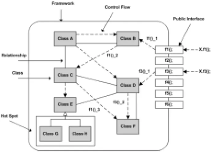
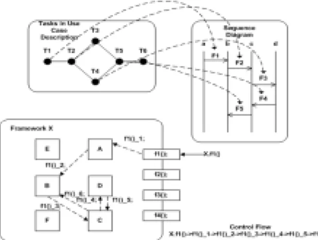
(2) skeleton of an implementation for an application. It is typically implemented as a set of abstract classes that define the core functionality of the framework along with concrete classes for specific applications included for completeness. Several different means of classifying frameworks have been proposed. Adair [7] defines three frameworks by scope, namely application, domain, and support frameworks. Johnson and Foote [2] define two types of frameworks, white box and black box by customization. Anderson Consulting [8] defines called and calling frameworks by how they interact with application extensions. 2.2 Framework Diagram Notation Frameworks consist of classes with a common functionality and have control flows among classes internally. Figure 1 shows a framework diagram notation. It consists of classes, relationship among classes, hot spots, control flows among classes and interfaces. Interfaces play a role of a path to communicate with other frameworks or classes. There are six interfaces, f1(), f2(), f3(), f4(), f5(), and f6() in Figure 2.5. Control flows of frameworks are indicated by forms of “interface name_control flow order”. By this notation, we know the interfaces as starting points of control flows and get flows of controls by numbering.. exist in variants and should be treat uniformly? (2) Is it possible to find a concrete concept that can be generalized? (3) Which parts of the system might change? (4) Where might a user want to hook custom code into the framework? The author suggests a two-phase framework design method to build an initial version of a framework; the first phase is called problem generalization and the second phase is called framework design [5]. Problem generalization starts from the specification of a representative application of the intended framework, and generalizes it in a sequence of steps into the most general (sensible) form. This phase typically makes use of the questions (1) and (2) to find the next generalization. During the second phase the generalization levels of the previous phase are considered in reverse order leading to an implementation for each level. The second phase make use of the questions (3) and (4) and of general design experience and domain knowledge to find the hot spots in the framework. The one of limitations of this method is that essential tasks to problem generalization or framework design are not defined concretely. Also, concrete guidelines to identify hot spot are not described in this method.. Figure 1 shows two control flows. One is X.f1() → f1()_1 → f1()_2 → f1()_3. And the other is X.f3() → f3()_1 → f3()_2. “X” represents a framework. And, f1() and f3() represent the interfaces of framework X to communicate with external world. 2.3 Existing Framework Development Methods 2.3.1 Design a Framework by Stepwise Generation When they design a framework, their main concern is to recognize things that should be kept flexible. These are called the hot spots [9] of the framework, i.e., the spots where the framework can be extended. In order to identify variant parts, some of questions are proposed as follows [5]:. 2.3.2 Developing Object-Oriented Frameworks Using Domain Models. (1) Which concepts of the problem domain. In this paper, they present an integrated. Figure 1. Framework Diagram Notation.
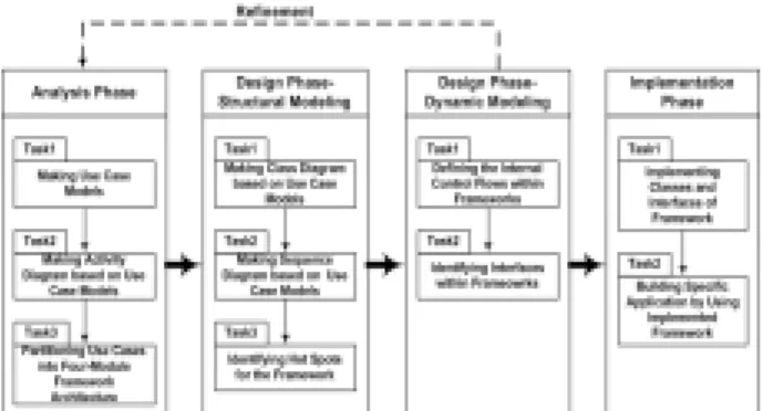
(3) approach to model the domain knowledge related to a framework and to map the identified domain models into object-oriented concepts [10]. The approach is described as follows:. As given in Figure 2, the object-oriented framework development process consists of three phases (e.g. analysis, design, implementation), and tasks for each phase are defined.. (1) They first model the top-level structure of frameworks using the so-called knowledge graphs.. Analysis phase consists of making use case models through extracting common functionality from a set of similar applications, making activity diagram based on use case models, and partitioning use cases into four-module framework architecture.. (2) Refining each node within a top-level knowledge graph into an acyclic sub-knowledge graph called knowledge domain. (3) They identify which nodes in a knowledge domain can be included together in the top-level knowledge graph. (4) Verifying whether the knowledge domains model the relevant knowledge, we match them against the use cases identified from the user requirements. (5) Finally, they map knowledge domains into object-oriented concepts. The main claim of this paper is that the framework refinement time may be reduced considerably by modeling the related domain knowledge explicitly. But, this paper just present five phase to developing framework, and within each phase they don’t define concrete methods or guidelines to develop framework.. Design phase consists of structural and dynamic modeling processes. The structural modeling consists of making class diagram based on use case models, making sequence diagram based on use case models, and identifying hot spots for the framework. The dynamic modeling consists of determining the internal control flows within frameworks and identifying interfaces within frameworks. Implementation phase consists of implementing classes and interfaces of framework and building specific application by using implemented framework.. 2.3.3 Framework Development with Domain Analysis In this paper [11], they outline how they use a domain analysis technique – Sherlock – to extract reusable frameworks and present a case study regarding the development of a graphic user interface framework for business and management information system.. Figure 2. Framework Development Process. Sherlock activities are definition of the context, domain characterization, and framework development.. 3.2 Analysis Phase. This paper present a domain analysis methodology targeted to frameworks such as Sherlock, which is the enabler to framework reuse. But, this methodology is not stabilized and no clear definition of all procedures.. Use case models are means to communicate requirements between customers and developers and to structure object models into manageable views. They offer a systematic and intuitive means of capturing functional requirements with a focus on value added to the user.. 3. UML-BASED OBJECT-ORIENTED FRAMEWORK DEVELOPMENT PROCESS. Use case models consist of use case diagrams and use case descriptions. A use case diagram shows the relationship between actors and uses cases. A use case description is structured as Figure. 3.1 Overview of Process. 3.2.1 Making Use Case Models.
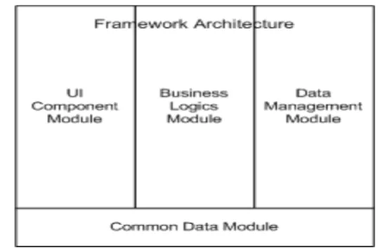
(4) 3., where each use case has a unique name. Use cases may additionally be numbered for quick identification in diagrams and in their textural form. Steps: (1) Initially, identifying actors. (2) Identifying use cases by listing all events from the outside environment to which we want to react. (3) Identifying communicates relationships between actors and use cases. (4) Identifying shared descriptions of functionality: In order to reduce redundancy, this sharing can be extracted and described in a separate use case that can then be reused by the original use cases. We show this reuse relation with a use relationship. (5) Identifying additional and descriptions of functionality.. partitioned set of actions. They are used to model the responsibilities of one or more objects for actions within an overall activity; that is, they divide the activity states into groups and assign these groups to objects that must perform the activities. Steps: (1) Structuring swim lanes. (2) Corresponding each use case in use case diagram to each activity. (3) Identifying event flow in use case description, we can define sequence between activities and conditions for outgoing transitions. (4) If use cases are very abstract, we decompose them into more concrete use cases. (5) Refining and elaborating as required.. optional. (6) Making use case descriptions for some use cases based on the notation in Figure 3. (7) Refining and elaborating as required.. 3.2.3 Partitioning Use Cases into Four-Module Framework Architecture By definition, the layered approach only allows a layer to communicate with the layers directly above and below it. Thus, in this task, we determine the modules of use cases on the degree of generality and specialty for each use case. The Framework is partitioned into four modules, which are UI Component Module, Business Logics Module, Data Management Module, and Common Data Module. The four-module framework architecture is depicted in Figure 4.. Figure 3. UML Notation for Use Case Description 3.2.2 Making Activity Diagram based on Use Case Models The way the individual use cases interrelate could be noted textually within the use case descriptions, but would not be very clear. Activity diagrams convey such relationships visually and therefore in a way that is easier to see.. 3.3 Design Phase – Structural Modeling. Activity diagrams can be subdivided into responsibility domains, the so-called swim lanes, which are graphically constructs that represent a. 3.3.1 Making Class Diagram based on Use Case Models. Figure 4. Four-Module Framework Architecture.
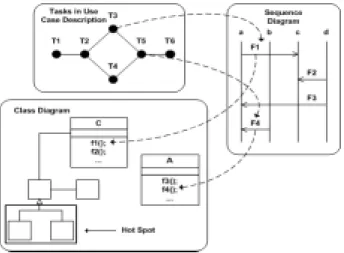
(5) Class diagrams are realizations of use cases. A class is the definition of the attributes, the operations, and the semantics of a set of objects. A class diagram describes the types of objects in the system and the various kinds of static relationships that exist among them. There are two principal kinds of static relationships: Associations (for example, a customer may render a number of videos) Subtypes (a nurse is a kind of person) Steps: (1) Making individual classes according to use cases of the four-module framework architecture in the analysis phase. (2) Tasks in use case descriptions are mapped to member functions of the specific classes in the class diagram. (3) Regard classes found in step2 as classes of the intended framework. (4) Making associations between classes and apply them to the intended framework.. functions signatures defined in the abstract classes. The function signatures of the abstract classes can be implemented differently according to the various applications. 3.3.4 Relationships among Diagrams for Structural Modeling In Figure 5, the use case description consists of six tasks, from T1 to T6. All of the tasks in use case description are mapped to the messages of the sequence diagrams. For example, T3 is mapped to F1 and T5 is mapped to F4. All of the messages in the sequence diagrams are mapped to the member functions of the classes. For example, F1 is mapped to function f1() in Class C and F4 is mapped to f4() in class A. Therefore, the tasks in use case description are mapped to the member functions of the classes in class diagrams. For example, T3 is mapped to f1() of class C and task T5 is mapped to f4() of class A. In the class diagram, an extracted hot spot is presented.. (5) Refining and elaborating as required.. 3.3.2 Making Sequence Diagram based on Use Case Models A sequence diagram shows a series of messages exchanged by a selected set of objects in a temporally limited situation, with an emphasis on the chronological course of events. Steps: (1) Regard classes of the class diagram as objects of the sequence diagram. (2) Tasks in use case descriptions are described as the messages in sequence diagrams.. Figure 5. Relationships among Diagrams for Structural Modeling. (3) Refining and elaborating as required. 3.4 Design Phase – Dynamic Modeling 3.3.3 Identifying Hot Spots for the Framework Guideline: In order to get the hot spots, we should extract common attributes and operations from classes in the class diagrams. And then we make abstract classes including them. The abstract classes are super classes and related concrete classes are sub classes. The abstract classes define function signatures without function bodies and concrete classes have implemented parts of the. 3.4.1 Defining the Internal Control Flows within Frameworks Steps: (1) Find the messages of the sequence diagrams mapped to the tasks of the use case description. (2) Find the message flows of the sequence.
(6) diagrams mapped to the control flows of the frameworks. 3.4.2 Identifying Interfaces within Frameworks Steps: (1) Find the method that is the starting point of the control flow. (2) Regard the found method as the interface. framework. Implementing framework interface is to implement control flows between classes contained in a framework. Second task is to build specific application by using implemented framework. This task applies framework to specific application and implements hook method through sub-classing hot spot in the case of white box approach and through composing object into framework in the case of black box approach.. of the framework. 3.4.3 Relationships among Diagrams for Dynamic Modeling Figure 6 shows the relationships between the use case descriptions and the sequence diagrams. Both the use case diagrams and the sequence diagrams are used to extract the control flows of the frameworks. In Figure 3.12., the flow of events of the use case description is T1 → T2 → T4 → T5 → T6. The flow of events is represented as the message flows of the sequence diagram, F1 → F2 → F3 → F4 → F5. The message flows in the sequence diagrams are mapped to the control flows among framework classes. In Figure 3.12., the flow of events in the use case descriptions is mapped to the control flow, f1()_1 → f1()_2 → f1()_3 → f1()_4f → f1()_5. X.f1() represents the framework interface.. 3.5.1 Implementing Classes and Interfaces of Framework Steps: (1) First of all, choosing the appropriate programming platform and language. (2) Architectural implementation: we implement the four-module framework architecture. (3) Outlining the file components: the source code that implements a class resides in a file component. Thus we must outline the file component and consider its scope, namely namespace. (4) Generating code from the operations and attributes that are defined in the class diagram. (5) Making the file component provide the. right interfaces. 3.5.2 Building Specific Application by Using Implemented Framework Steps: (1) First, implementing Common Data Module of implemented framework through inheritance or composition and overriding hook methods.. Figure 6. Relationships among Diagrams for Dynamic Modeling 3.5 Implementation Phase Implementation phase consists of two tasks. First task is to implement classes and interfaces of. (2) Next, implementing Data Management Module of implemented framework through inheritance or composition and overriding hook methods with suitable data management algorithms. (3) Next, implementing Business Logics Module of implemented framework through inheritance or composition and overriding hook methods with algorithms of business logics..
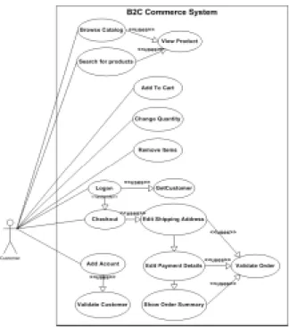
(7) (4) Finally,. implementing UI Component Module of implemented framework and reusing the UI components of implemented framework or adding specific user interfaces of your own application.. structure the activity diagram into swim lanes that are Main Process, Business Logics, and Data Management. We also decompose the use cases of the use case diagram in Figure 7 to more concrete use cases to fulfill the purpose of swim lanes.. 4. CASE STUDY In this section, we apply the mapping techniques between UML diagrams and framework diagrams to the Business-to-Consumer Electronic Commerce (EC) domain. Currently, EC is a spotlighted field and it will be very useful for development of applications if efficient EC frameworks are developed. Many of web applications for B2C EC domain have been established. Therefore, we collected similar application requirement specifications and extracted common functions from them. The common functions are ‘Searching For Products’, ‘Browsing Catalog’, ‘Account’, ‘Shopping Cart’, and ‘Checkout’. The use case diagram for these functions is depicted in Figure 7. Figure 8 shows a use case description for use case Search for Products.. Figure 8. Use Case Description for Search for Products After determining activity diagram, we partition the use cases into four-module framework architecture, which is depicted in Figure 10. In the structural modeling of design phase, we should construct a class diagram (Figure 11) based on four-module framework architecture that is depicted in Figure 10. Then, we make sequence diagrams (Figure 12) for different use cases. Next, we identify the hot spots of the intended framework (Figure 13).. Figure 7. Use Case Diagram for B2C EC Domain Sequence and workflow of among use cases in a framework are described through activity diagram, which is depicted in Figure 9. We. Figure 9. Activity Diagram for B2C EC Domain.
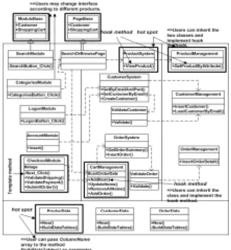
(8) Figure 12. Sequence Diagram for Use Case Search for Products Figure 10. The Four-Module Framework Architecture for B2C EC Domain. Figure 13. Identifying Hot Spots for B2C EC Domain Figure 11. The Class Diagram for B2C EC Domain Figure 14 shows the final framework diagram. The start points of the internal control flows of the framework are the interfaces of the framework. In the implementation phase, we choose Microsoft .NET Framework as the platform and VB.NET as the programming language. Then we implement all classes and interfaces of the Framework B2C that are depicted in Figure 14. Next, we build the specific application by using the implemented Framework B2C. We inherit the abstract classes and override the hook method from the Framework B2C.. Figure 14. The Final Framework Diagram for B2C EC Domain 5. CONCLUSIONS In this paper, we proposed a practical.
(9) object-oriented framework development process that is based on UML notations and semantics. We defined development phases (analysis, design, implementation) and tasks for each phases. We defined essential tasks for framework development and applied UML notations to each task. Each task is given a set of steps on how to carry out the task. Since the proposed process is based on UML diagrams and the basic Objectory process, we believe that object-oriented frameworks can be more efficiently developed by utilizing the proposed process, and higher quality object-oriented frameworks can be produced. 6. REFERENCES [1] Roberts D., Johnson R., Evolving Frameworks: A Pattern Language for Developing Object-Oriented Frameworks, Proc. of PloP’96, Third Annual Conference on the Pattern Languages of Programs, 1996. [2] Johnson, R. and Foote, B., Designing reusable classes, J. Object Oriented Program. 2(1), 22-35, 1988. [3] Nikas Landan, Axel Nikasson, Development of Object-Oriented Frameworks, Master Thesis, Dept. of Communication Systems, Lund Univ., Sweden, 1995. [4] Jan Bosch, Peter Molin, Michael Matsson, PerOlof Bengtsson, Object-Oriented Frameworks – Problem & Experiences, Dept. of CS & BA, Univ. of Karlskrona, Sweden, 1999. [5] K. Koskimies, H. Mossenbock, “Design a Framework by Stepwise Generalization”, 1997. [6] Martin Fowler, UML Distilled, 2nd Edition, Addison-Wesley, 2000. [7] Adair, D., Building object-oriented frameworks, AIXpert, Feb. 1995. [8] Sparks, S., Benner, K., and Faris, C., Managing object-oriented framework reuse, IEEE Comp., 29(9), 52-62, 1996. [9] W. Pree, “Meat Patterns – A means for capturing the essential of reusable object-oriented design,” Proceedings of the 8th European Conference on Object-Oriented Programming, Bologna, Italy, 1994. [10] M. Aksit, F. Marcelloni, B. Tekinerdogan,. Developing Object-Oriented Frameworks Using Domain Models, ACM Computer Surveys (CSUR), March, 2000. [11] G. Succi, A. Valerio, T. Vernazza, M. Fenaroli, P. Predonzani, “Framework Extraction with Domain Analysis”, ACM Computing Surveys, Vol.32, No.1, March 2000..
(10)
數據
+4
相關文件
Making use of the Learning Progression Framework (LPF) for Reading in the design of post- reading activities to help students develop reading skills and strategies that support their
The Seed project, REEL to REAL (R2R): Learning English and Developing 21st Century Skills through Film-making in Key Stage 2, aims to explore ways to use film-making as a means
After teaching the use and importance of rhyme and rhythm in chants, an English teacher designs a choice board for students to create a new verse about transport based on the chant
Lin, A smoothing Newton method based on the generalized Fischer-Burmeister function for MCPs, Nonlinear Analysis: Theory, Methods and Applications, 72(2010), 3739-3758..
Moreover, for the merit functions induced by them for the second-order cone complementarity problem (SOCCP), we provide a condition for each stationary point being a solution of
Moreover, for the merit functions induced by them for the second- order cone complementarity problem (SOCCP), we provide a condition for each sta- tionary point to be a solution of
• Use table to create a table for column-oriented or tabular data that is often stored as columns in a spreadsheet.. • Use detectImportOptions to create import options based on
• use Chapter 4 to: a) develop ideas of how to differentiate the classroom elements based on student readiness, interest and learning profile; b) use the exemplars as guiding maps to
