Proceedings of the 25" Annual International Conference ofthe IEEE EMBS
Cancun, Mexico * September 17-21,2003
Head-Controlled Device with M3S-Based for People with Disabilities
Show-Hong Chen', Yu-Luen Chen3, Ying-Han Chioul, Jen-Cheng Tsai', Te-Son Kuo'*~
'Department of Electrical Engineering, National Taiwan University, Taipei, Taiwan, R.O.C. Graduate Institute of Biomedical Engineering, National Taiwan University, Taipei, Taiwan, R.O.C. 'Department of Electronic Engineering, Hwa-Hsia College of Technology and Commerce, Taipei, Taiwan, R.O.C.
Absfract- The motivation of this research is to improve the ability of ambulation for people with a certain degree of disability. The control method is using two tilt sensors~as an inputsontrolling module. One of the Nt sensors detects the anteriorlposterior tilting of the head and moves the wheelchair or mouse cursor forwerdlbackward, the other distinguishes the lefffright swing of the head. In order to increase the safety of this system, the M3S protocol established by the European Commission is also applied to this research. The system based on M3S protocol has the advantage of real-time monitoring for people with severe disabilities.
K e y w o r d s M3S, People with Disabilities, Tilt Sensor, Wheelchair, Mouse
I. INTRODUCTION
Due to different degrees of disabilities, controlling methods of the wheelchair can be roughly sorted into two categories. The fnst method is suitable for the average physically challenged (e.g. joystick control), whereas the second one is suitable for the severely spinal cord injured
(SCI) patients (such as voice recognition, electromyographic
signal, etc.).
The Richard C. Simpson and Simon P. Levine's voice control method [3] is fit for a variety of people with disabilities; the controlling signals are obtained directly from the users' voice. However, the voice recognition module has to be fully trained before handling such duties. A different user would then be obliged to have an overall training of the same system again, which is a tedious task. By the way, error rates of the recognition module are greatly influenced by the stochastic background noise, especially during the ambulation of the system.
In comparison with the joystick control method, an SCI patient of the higher level could only depend on the movements of the head. In this research, a head controlled device designed for SCI patients, would utilize the position of the head-swing and decide whether the wheelchair should move forwardhackward or make a tum. Furthermore, he/she could switch and control the different output devices via an identical input that are integrated in the computer system of the wheelchair. The user can use the unique input device, which he/she is most familiar to, and he/she takes full control of the operation of this integrated system. Besides, the Multi Master Multi Slave (M3S) protocol is applied in order to fulfill the requirements for our system. The aims of the standard M3S protocol are as follows [4]:
0-7803-7789-3/03/$17.00 02003 lEEE
(I)
To provide the wheelchair user with optimal control over his mobility, and personal communications through one input device best suited to the user's needs.(2) To allow easy modification or expansion of a wheelchair's facilities as his needs change.
(3) To ensure that the wheelchair user is safe.
11. METHODOLWY
This system consists of one input device and two output devices. All devices are connected with the bus. The system is constructed as illustrated in Fig. 1, ( 1 ) tilt sensor module,
(2) the signal processing module, (3) controller area network (CAN) module. This system uses a head-controlled device instead of using joystick so that the corresponding analog voltage could be gathered by the tilt sensor in different levek. Afrer the conversion of 10 bits digital voltage, the analog voltage level signal is transmitted to the analog to digital converter (ADC) circuit and then to the Pulse Width Modulation (PWM) module. Then, it can either modulate the time length of the motor action, or transmit the digital voltage from the ADC circuit to the personal computer via RS232 and execute the corresponding displacements of the mouse cursor. The detailed information about this system is as follows:
1) The Tilt Sensor Module: The tilt sensor module contains two tilt sensors and one cheek touch switch containing IeWright switch. The output voltage of the tilt sensor is proportional to the angle of the tilting position, for example: now giving 5V DC power supply on the tilt sensor module, if the angle
of
the tilt is equalto
90", the Corresponding maximum output voltage will be 3.26V; if the angle of the tilt is equal to -90", the consistent minimum output voltage will be 1.74V. The neutral output voltage of the tilt sensor after calibration is 2.5 V without variation of the angle. Due to this system is designed for SCI patients, the ranges of the angles must be restrict between -45" and+45", and the corresponding voltage varies between 2.12V
and 2.88V. Therefore, the output device will move to corresponding position due to different voltage changes. The final target of this system is to integrate the computer mouse and wheelchair, the user only use the cheek touch switch to change the output device, e.g. controlling the motor driven circuit or computer mouse system. However, considering the priority decision of the output device, the motor driven circuit is higher than computer mouse system. The initial
state of the system is the wheelchair operation when the user puffs her cheek to trigger the touch switch the state of the system is changed into the computer mouse system. After closing the computer mouse system, the system will he set to the most priority state: motor driven circuit.
2 ) The Signal-Processing Module: In this system, the signal processing module comprises two parts: the ADC of the input device and the PWM of the output device.
IO
bits ADC circuit converts the analog voltage of the tilt sensor into the binary digital voltage. The digital voltage is produced by the ADC circuit to create the corresponding pulse width signals in PWM module. The PWM signal controls the current and the power of the Motor circuit via modulating the pulse width; it generates predictably the rotational speed and the torque through the motor driven circuit.3) Controller Area Network (CAN) Module: The kernel of CAN module is a digital signal processor (DSPS320F243), using a serial communication protocol which supports the distributed control in real time. The main job of the CAN module is the decision of the output devices transition, priority of each device, and real-time monitoring for device safety. Furthermore, it can provide the optimal control for operating in noisy and harsh environments, to make sure the extreme safety for user. The data frame is transmitted via the two port of the CAN (CANTX and CANRX) on the bus that is called the CAN bus. The data frame mainly consists of seven fields: start of the frame, arbitration field, control field, data field, cyclic redundancy check (CRC) field, acknowledgment and end of frame hits on the bus [I-21. Each device has the CAN module on the system,
so
it must declare the priority of the transmission of each device before the development. The input device will transmit the converted data to the consistent output device. The setup is as follows:Data Transmission and Reception: After CANTX and CANRX of the CAN module have received the digital data which is transmitted by the ADC module, it stores temporarily the digital data in the MBOXnA,B (data storage field) of the MAILBOXA,B, respectively. The arbitration field is to determine the priority of the data that is stored in the MSGIDnH,L (message identifier for high, low word mailboxes) of the MailBoxn. The input device must setup the Accceptance Mask Enable (AME) bit by matching the arbitration field one by one to ensure the connection between input and output device. Similarly, it has a CAN module in each output device. The content of the identifier field of each output device should he the same as the input device, and the AME bit should also be set zero. After clicking the touch switch device, it will send the low voltage level to the system kernel to change the priority number in input device. A new output device with the same priority number in input device will he chosen.
Safety Monitoring & Error Detection: To monitor and to make sure the device in accurate operation, the method of the safety monitoring is to check the Global
a)
b)
Status Register (GSR). A f e r the data frame has been transmitted on bus, the Transmit Mode (TM) bit will be equal to 1 in the input device. When a received frame message has been stored in a MailBoxn, the Receive Mode
(RM)
bit will be set 1 automatically by the CAN module of the output device. Therefore, it can detect the correct status of the transmission and reception via detecting theTM
andRM bit. About the input device accurately connects with corresponding output device is to check the Error Status Register (ESR) whether the: Bit Error Flag (BEF) will be equal to 1, which is determined a dominant bit is transmitted hut a receive bit is received during transmission of the arbitration field.
111. RESULTS
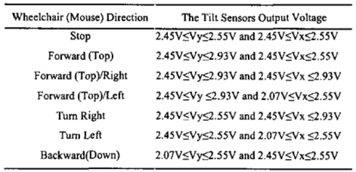
This system integrates two output devices to perform the multi-control via unique input device. It is necessary to make sure the safety for the SCI patients using the head- controlled device which applies to the M3S specification in this system. In order to avoid the slight swing movement of the head, there is the small ineffective ranges from 2.45V to 2.55V in default output voltage of the tilt sensor to make sure the device in accurate operation. The output voltage of the tilt sensor is corresponding to the output displacement as shown in Table I. The relationship function of Vx and Vy is: v x =VOIVG
where Vx or Vy is the actually changeable voltage range of the tilt sensor, VO is the primary output voltage of the tilt sensor, V6 is the default offset voltage such
as
dead band range.,
v y =VO+V6
IV. DISCUSSION & CONCLUSION
The objective of this paper is to improve the ability of
ambulation for people with a certain degree of disability in
our system, each device has a CAN module is used to detect its status, replies properly own error to the input deice,
so
that the system can hold the optimum status for SCI patients. Furthermore, it can apply hvo lines
for
safety features(SAF
bus) that includes the dead
man
switch (DMS) line andKEY
line switch to increase operating safety. In this paper, the user can also expand the suitable devices to the system without modifying the system construction. It only sets the priority and serial number of the arbitration field in each device, then it can correctly transmit and receive the data to make sure the link between input and output device properly. More research and system modification will be done in the near future.REFERENCES
[I] TMS320F243/F241lC242 DSP Cotustrollers Reference Guide
Syslem and Peripherals Literature Number: SPRU216C January [Z] M3S specification , version 2.0 from the Dissemination office, TNO Institute of Applied Physics, P.O. BOX ISS,NL 2600 AD Dclfl, The Netherlands.
[3] Richard C. Simpson and Simon P. Levine, "Voice Control of a
Powered Wheelchair" IEEE trans. On Neural Systems and Rehabilitation Engineering, vol. IO, N0.2, June 2002.
[4] Sven Limman "M3S The Local Network for Electric Wheelchairs and Rehabilitation Equipment" IEEE mans. On Rehabilitation engineering, v01.4,N0.3, September 1996. J. Beebe, "Signal wnversion (Book stylc with paper title and editor)," in Biomedical Digital Signal Processing, W. 1. Tompkins, Ed, Englewood Cliffs, N I Prentice-Hall, 1993, eh. 3, pp. 61-74. 2000.
TABLE
ITHE RELATIONSHIP BETWEEN THE TILT SENSOR OUTPUT VOLTAGE AND WHEELCHAIR POSITION
Wheelchair (Mouse) Direction The Tilt Senson Output Voltage slop 2.4SVSVyS2.SSV and 2.45V5Vx52.SSV Forward (Top) 2.4SVSVyS2.93V and 2.4SV5Vx52.SSV 2.4SVsVys2.93V and 2.4SV5Vx 4 . 9 3 V 2.4SV5Vy 4 . 9 3 V and 2.0lV5Vvx52.SSV 2.4SV5Vy4.5SV and 2.45VSVx 52.93V 2.4SV5Vy52.SSV and 2.07VsVx 52.SSV Backward(Down) 2.0lVsVyS2.SSV and 2.45VsVvx4.SSV Forward (TopyRight Forward (Top)lLcft Tum Right Tuum Lee ... ~
;e;
CAN pwu-
I
. . IWYI :.
.
1oc : : . . ... I i ... ;Fig. I . The system constmction based on M3S.