國立交通大學
電控工程研究所
博士論文
基於 ZigBee 智慧型環境與移動式機器人之
位置感知系統設計
Design of Location Aware Systems using
ZigBee-based Intelligent Environment and Mobile
Robots
研 究 生:林嘉豪
指導教授:宋開泰 博士
基於 ZigBee 智慧型環境與移動式機器人之位置感知
系統設計
Design of Location Aware Systems using
ZigBee-based Intelligent Environment and Mobile
Robots
研 究 生:林嘉豪 Student: Chia-How Lin
指導教授:宋開泰 博士 Advisor: Dr. Kai-Tai Song
國 立 交 通 大 學
電 控 工 程 研 究 所
博 士 論 文
A Dissertation
Submitted to Institute of Electrical Control Engineering College of Electrical and Computer Engineering
National Chiao Tung University in Partial Fulfillment of the Requirements
for the Degree of Doctor of Philosophy
in
Electrical Control Engineering June 2013
Hsinchu, Taiwan, Republic of China
基於 ZigBee 智慧型環境與移動式機器人之位置感知
系統設計
學生:林嘉豪
指導教授:宋開泰 博士
國立交通大學電控工程研究所
摘要
位置感知機器人系統透過智慧型環境中特定物體、使用者或機器人本身之位置及這 些位置所在的感測資訊提供適當的服務。ZigBee 無線感測網路由於成本低廉且功耗較低, 適合用來佈建智慧型環境。本論文之主旨即在於利用 ZigBee 建構之智慧型環境,結合移 動式機器人,提出一套能主動提供服務的位置感知服務系統。為了方便建置 ZigBee 無線 網路之位置感知系統,本論文發展一套以機率為基礎的無線訊號強度定位演算法。此演 算法只需要一次的校正即可應用於不同的環境,並維持一定的準確度。另一方面,為了 提供更低廉的機器人自主導航解決方案,本論文提出以單眼視覺為基礎的地平面偵測方 式進行環境中物體的偵測及物體距離量測,藉此可進而達成環境結構的估測,以利機器 人避障控制。本方法僅需單一攝影機即可在移動平台上偵測其障礙物之距離,不需要使 用特殊攝影機或者融合其他感測器資訊。本方法之特色在於融合了反向投影以及色彩分 割以穩定的分類地面/非地面區域,可以更加穩定在不同特性的地面和障礙物環境中同時 偵測出靜態與動態障礙物。在實際實施應用上本方法僅限制地面為平面,不限定環境中 地面及障礙物材質或顏色特性、不需要特定標號、亦不需要先對環境或障礙物特性進行 學習。本方法估測結果為 2D 平面上物體之距離與分佈地圖,因此除了可直接用以取代傳統距離感測器,亦可根據所建構之環境地圖進行路徑規劃。本論文在整合實驗中展示 此位置感知系統針對入侵者偵測和即時提供使用者服務兩個情境應用,以驗證所發展方 法之有效性。
Design of Location aware Systems using ZigBee-based
Intelligent Environment and Mobile Robots
Student: Chia-How Lin
Advisor: Dr. Kai-Tai Song
Institute of Electrical Control Engineering
National Chiao Tung University
ABSTRACT
A location aware system provides location information of objects, users and mobile robots from sensor nodes deployed in the intelligent environment. The information can be used to support various intelligent behaviors of a service robot in day-to-day application scenarios. This thesis presents a probability-based approach to building a location aware system. With this approach, the inconsistencies often encountered in received signal strength indicator (RSSI) measurements are handled with a minimum calibration. By taking off-line calibration measurement of a ZigBee sensor network, the inherent problem of signal uncertainty of to-be-localized nodes can be effectively resolved. The proposed RSSI-based algorithm allows flexible deployment of sensor nodes in various environments. The proposed algorithm has been verified in several typical environments and experiments show that the method outperforms existing algorithms. The location aware system has been integrated with an autonomous mobile robot to demonstrate the an on-demand robotic intruder detection system.
To provide a low-cost autonomous navigation solution, we have developed monocular vision system to estimate distances between the robot and obstacles based-on inverse perspective transformation (IPT) in image plane. A robust image processing procedure is proposed to detect and segment drivable ground area within the camera view. The proposed method integrates robust feature matching with adaptive color segmentation for plane
estimation and tracking to cope with variations in illumination and camera view. After IPT and ground region segmentation, a distance measurement result is obtained similar to that of a conventional laser range finder for mobile robot obstacle avoidance and navigation. The merit of this method is that the mobile robot has the capacity of path finding and obstacle avoidance by using a single monocular camera. Practical experimental results on a wheeled mobile robot show that the proposed imaging system successfully estimates distance of objects and avoid obstacles in an indoor environment. Several interesting integrated experiments are presented in this thesis to demonstrate the effectiveness of the location aware robotic system in a home setting.
誌謝
攻讀博士學位的過程是未進入博士班前所無法想像的,這是一條辛苦而又漫長的自 我成長之路。一路走來,由衷感謝我的指導教授宋開泰博士,感謝他多年來在我多次感 到氣餒之時不斷給予鼓勵,使我終能順利到站,展開人生新的旅途;另一方面,在專業 及論文寫作上的指導,不厭其煩的給我建議及修正方向,使我受益良多,也讓本論文得 以順利完成。亦感謝論文口試委員-陳永平教授、莊仁輝教授、郭重顯教授及葉廷仁教 授對於本論文的種種建議與指引,強化本論文的嚴整性與可讀性。 感謝學長戴任詔博士、蔡奇謚博士、韓孟儒博士對本論文的建議與討論,同時亦感 謝過往相互鼓勵的實驗室碩士班學弟妹巧敏、信毅、格豪、允智、崇民、松歭、俊瑋、 富聖、振暘、晉懷、濬尉、仕傑、煥坤、舒涵、科棟、奕文、哲豪、仕晟、建宏、上畯、 章宏、昭宇、俊儒、京叡、依穎、明翰等在實務驗證時所提供的協助,以及生活上所帶 來的樂趣。 另外,特別感謝我的父母,由於他們辛苦栽培,在生活上給予我細心地關愛與照料, 使我才得以順利完成此論文;也感謝朋友們的加油打氣,在我最無助及失意的時候給予 背後安定的力量。願能貢獻一己棉薄之力,成就有益家庭、社會之能事。Contents
摘要 ... I ABSTRACT ... III 誌謝 ... V CONTENTS ... VI LIST OF FIGURES ... VIII LIST OF TABLES ... XI
CHAPTER 1. INTRODUCTION ... 1
1.1 MOTIVATION ... 1
1.2 LITERATURE REVIEW ... 3
1.2.1 Localization of ZigBee-Based Wireless Sensor Network ... 3
1.2.2 Vision-based Mobile Robot Navigation ... 7
1.3 RESEARCH OBJECTIVES ... 10
1.4 ORGANIZATION OF THE THESIS ... 11
CHAPTER 2. PROBABILITY-BASED LOCATION AWARE DESIGN ... 12
2.1 INTRODUCTION ... 12
2.2 PROPOSED ZIGBEE LOCALIZATION METHOD ... 12
2.2.1 Modeling of RSSI vs. Distance Relationship ... 13
2.2.2 2D Probability Map ... 14
2.2.3 Filtered 2D Probability Map ... 16
2.2.4 Location Estimation ... 17
2.3 ROBUSTNESS TEST OF THE PROPOSED LOCALIZATION ALGORITHM ... 19
2.4 SUMMARY... 21
CHAPTER 3. MONOCULAR VISUAL NAVIGATION DESIGN ... 26
3.1 INTRODUCTION ... 26
3.2 SYSTEM OVERVIEW ... 27
3.3.1 Ground Feature Detection ... 30
3.3.2 Ground Region Segmentation ... 34
3.3.3 Obstacle Detection ... 35
3.4 CALIBRATION EXPERIMENT OF DISTANCE MEASUREMENT ... 37
3.5 SIMULATION RESULTS OF SYNTHETIC IMAGES ... 39
3.6 SUMMARY... 40
CHAPTER 4. LOCATION AWARE SYSTEM DESIGN ... 42
4.1 INTRODUCTION ... 42
4.2 INTELLIGENT ENVIRONMENT ... 42
4.2.1 Intrusion Detection Sensors ... 42
4.2.2 Visualization System ... 44
4.2.3 Speech Recognition system ... 47
4.2.4 OSA platform ... 48
4.3 MOBILE ROBOT SYSTEM... 49
4.3.1 Agent-based Control System ... 50
4.3.2 Mobile Robot Localization ... 50
4.3.3 Autonomous Navigation System ... 51
4.3.4 Human Detection and Tracking ... 53
4.4 SUMMARY... 54
CHAPTER 5. EXPERIMENTAL RESULTS ... 55
5.1 INTRODUCTION ... 55
5.2 HUMAN-MACHINE-INTERFACE IN INTELLIGENT ENVIRONMENT ... 55
5.3 MOBILE ROBOT OBSTACLE AVOIDANCE ... 56
5.4 INTRUDER DETECTION APPLICATION ... 61
5.5 ROBOT-ON-DEMAND EXPERIMENT ... 63
5.6 SUMMARY... 70
CHAPTER 6. CONCLUSION AND FUTURE WORKS ... 73
6.1 GENERAL CONCLUSIONS ... 73
6.2 FUTURE WORKS ... 74
List of Figures
Fig. 1-1: An example of RSSI irregularity. ... 6 Fig. 2-1: The flow chart of the proposed localization algorithm. ... 14 Fig. 2-2: Probability histogram of distance for RSSI = –88 dBm. ... 15 Fig. 2-3: The 2D pdf of a fixed RSSI reading between a reference node and a mobile node.
... 16 Fig. 2-4: An example of how filtered 2D maps obtained from different reference nodes are combined into the final map. ... 18 Fig. 2-5: Data flow of the ZigBee localization experiments. ... 20 Fig. 2-6: (a) Experimental environment 1 (EE1): the lab 622 and corridor (b) the location of deployed ZigBee beacons in the experiment (filled circles). ... 22 Fig. 2-7: (a) Experiment Environment 2 (EE2): the corridor of lab building, (b) the location of deployed ZigBee beacons in the experiment (filled circles). ... 23 Fig. 2-8: (a) Experiment Environment 3 (EE3): the lobby of the lab building (b) the location of deployed ZigBee beacons in the experiment (filled circles). ... 24 Fig. 3-1: Homography of coplanar points between image plane and ground plane. ... 27 Fig. 3-2: The architecture of the proposed MonoVNS. ... 29 Fig. 3-3: An example of ray casting in an image after IPT. The white area indicates the ground region. The dark area indicates obstacles. The distances between the camera center and obstacles can be estimated by measuring the length of the rays. ... 30 Fig. 3-4: Homography of coplanar points observed from two images. ... 31 Fig. 3-5: An example of ground feature detection. (a) and (b) are images taken in different views. (c) is the classification result of the matched features observed from (a) and (b). The features with blue label indicate features on the ground, while the features with orange label are features off the ground. ... 33 Fig. 3-6: (a) Color segmentation result and (b) ground region labeling result based on the images in Fig. 3-5. ... 37 Fig. 3-7: The obstacle used in the experiment. (a) the robot is 6m away from the obstacle (b) the robot is 1.6m away from the obstacle. ... 38
Fig. 3-8: The synthetic room experiment. (a) The structure of the environment. (b) A classification result. The red zone indicates the region correctly labeled as ground,
while the yellow region indicates false detection. ... 40
Fig. 4-1: Intruder detection module (a) hardware of the module (b) signal of the pyro sensor (c) signal of the microphone. ... 43
Fig. 4-2: An example of the “target marking” of the visualization system. (a)The map of the experiment environment. (b)The graphic user interface and the view of the pan-tilt camera at coordinate (8,-1) ... 47
Fig. 4-3: Snapshots from the experimental result of the “target marking” of the visualization system. (a) the person was at the coordinate (0,0) (b) the person was at the coordinate (0,6) (c) the person was at the coordinate (8,-1) ... 47
Fig. 4-4: OSA network services applied in the proposed system ... 49
Fig. 4-5: System architecture of autonomous navigation using behavior fusion design.. .... 52
Fig. 4-6: Examples of the human detection system: (a)human body detection, (b)face detection ... 54
Fig. 5-1: An example of the “asking-for-help” scene ... 56
Fig. 5-2: The mobile robot used in the navigation experiment. ... 57
Fig. 5-3: The navigation design of the experimental mobile robot ... 57
Fig. 5-4: The scale of the view from the mobile robot after IPT. ... 58
Fig. 5-5: The recorded trajectories of navigation experiments using the proposed MonoVNS and the URG-04LX-UG01 laser range finder. Label (a)-(l) represent the position of the robot in Fig. 5-6. (a)-(l). ... 58
Fig. 5-6: Snapshots from the navigation experiment... 59
Fig. 5-7: Experimental results of ground detection and pedestrian detection ... 60
Fig. 5-8: The hardware arrangment of an intruder detection system. ... 61
Fig. 5-9: Flowchart of the proposed intruder detection system ... 62
Fig. 5-10: The process and the images acquired by the robot in the intruder detection experiments: (a) a person claped his hands near the microphone; (b) the robot received the alert and moved to the person; (c) the robot took the person’s image and sent it to the user; (d) a person walked into the room from the doorway; (e) the robot received the alert and moved to the person; (f) the robot took the person’s image and sent it to the user; (g) a person (acting as a theif) intruded into the room; (h) the robot received the alert and moved to the person; (i) the robot took the image and sent it to the user. ... 64
Fig. 5-11: Snapshots of the intruder detection experiment corresponding to Fig. 5-10. ... 65 Fig. 5-12: The robot trajectory in the intruder detection experiment. The mark (a)-(i) represent the corresponding location of the robot in 5-10 (a)-(i) ... 65 Fig. 5-13:System Architecture of the dual arm mobile manipulator. ... 66 Fig. 5-14: The dual-arm mobile manipulator; (a)the mechanical design of the mobile manipulator; (b) a recent photo of the robot and the key components of the mobile manipulator. ... 67 Fig. 5-15: The user wearing two sensor modules in the experiment. ... 69 Fig. 5-16: Snapshots of phase 1 experiment; (a)The robot was at standby mode; (b) The robot took the package from the delivery man;(c) the robot delivered the package to the user; (d) The robot went back to the rest zone. ... 71 Fig. 5-17: Recorded trajectory of the robot and the user in phase 1 experiment. ... 71 Fig. 5-18: Snapshots of phase 2 experiment; (a)The the user had a heart attack; (b) The robot offered its hands to comfort the user;(c) the robot took a drug can from the cupboard; (d) The robot handed the drug to the user. ... 72 Fig. 5-19: Recorded trajectory of the robot in phase 2 experiment ... 72
List of Tables
Table 2-1: Configurations of Test Environments ... 21
Table 2-2: Estimation Error Comparision: EE1 ... 22
Table 2-3: Estimation Error Comparision: EE2 ... 23
Table 2-4: Estimation Error Comparision: EE3 ... 25
Table 3-1: Experimental Result for Distance Measurement by Using the proposed MonoVNS ... 39
Chapter 1.
Introduction
1.1
Motivation
As a result of the progress of medical technology and the reduction in birthrate in recent years, the population ratio of the elderly has been increasing in many countries. Elderly-care services will soon become essential and cause social problems in the near future. Technology can play an important role in this issue by providing solution to reduce the man power needed for such labor-intensive work and increase the quality of life of the elderly.
One interesting area is the intelligent environment, which can gather user and environment information spontaneously via context aware systems. It also provides the connectivity to distribute information remotely via wireless sensor networks (WSNs) and internet. For instance, a family member can request or subscribe the images and location information of the elderly through e-mail or cell phone. The location of the elderly is then estimated using the wireless sensor module attached. The location server then collects the information, and sends to the video server. The video server controls all the cameras in the house and thus can select a proper camera to acquire images of the elderly according to the location information provided by the location server. Finally, all the information will be sent to the user B to ensure the exact situation of the elderly. The elderly can also ask for help via speech recognition system. Family members will be alerted using the same infrastructure. In practice, however, the coverage of the camera may not be complete, and even if the event is monitored, the system cannot provide any physical aid.
Another interesting area is the mobile robot. The development of robotic security and monitoring systems for indoor environments such as factories, offices or home settings has gained increasing attention in recent years [1-3]. A mobile robot can provide sufficient mobility and flexibility to help security guards which lowers the relative cost as long as the demand for adequate security is satisfied. Furthermore, it has the ability to help the elderly physically. However, robots are still far from practical for daily-life use in many circumstances, especially in a home setting. One critical reason is that they lack the capability to gather sufficient information of the environment in order to adapt their changes in real-life application scenarios. For instance, under the scenario of a user having an asthma attack, the robot should have the following capabilities. The robot should notice the incident immediately by monitoring the bio-physical situation of the user. After detecting the emergency situation, the robot should be able to plan a task to resolve the problem, that is, to bring the quick-relief medicines to stop asthma symptoms. In order to accomplish the planned task, the robot should be able to locate the medicines and user, and to navigate to their location autonomously. For an on-demand robotic system, a locational aware module is required to provide location data of objects of interest, users and of the mobile robot itself. This information supports various intelligent behaviors of a service robot in day-to-day scenarios. According to the reasons above, this thesis aims to investigate the location aware system using intelligent environment and mobile robots, and establish a practical on-demand robotic system to assist the security and healthcare of elderly at home.
Taking home security as an example, conventional surveillance systems have various limitations and shortcomings. A security agent employing conventional security systems has to dispatch security guards to respond to alarms. This creates a heavy burden for security agencies, especially considering a high portion of alarms are actually false alarms. Furthermore, it normally takes some time for the security guard to reach the alarm location to handle the
situation. Critical time may have already been lost by the time the security guards arrive on the scene. The combination intelligent environment and mobile robots can solve this problem. By deploying the wireless sensor network (WSN) and security cameras all over the guarding area, false alarm can be reduced. In addition to passive monitoring, the mobile robot can take place the security agent to check the alarm spots more actively and agilely.
1.2
Literature Review
1.2.1
Localization of ZigBee-Based Wireless Sensor Network
In the past decade, the production of various off-the-shelf devices for wireless sensor networks (WSNs) has progressed rapidly and such devices can support the use of on-demand robotic systems. WSNs are constructed using a series of sensor nodes deployed throughout the monitored environment. These sensor nodes are connected and communicate with each other over a wireless network such as wireless LAN, Bluetooth, ultra-wide band or ZigBee. This allows the use of free-ranging, autonomous service robots which operate in human centered environments to assist people. Because the robot has limited onboard sensing and computing abilities, integrating service robots with a WSN is desirable to enable robots to be used for more practical applications. A WSN can serve as a low-cost, distributed and easily deployed monitoring system which extends the limited sensing capability of the robots.
Unlike a stand-alone security robot, which is normally equipped with a variety of sensors but still has only a limited sensing range, on-demand security robots can obtain thorough sensory information of the guarded area and make it available on line. When integrated with the WSN, a security robot can acquire information from the entire sensed environment in real time. To enhance the prompt response of security robots to an intrusion situation, many researchers have studied the application of WSN and mobile robot techniques for use in security and monitoring [4-5]. WSN-based localization can estimate the location of a mobile
node with an initially unknown position in a sensor network using available a priori knowledge of positions of a few specific reference nodes in the network. However, most of these designs require overly complex and impractical installation procedures and suffer from problems with signal calibration/training. For example, some wireless sensor modules have to be placed in restricted locations such as on a ceiling [3]. Among off-the-shelf WSN technologies, ZigBee is a popular ad hoc network based on the standard IEEE 802.15.4. ZigBee Alliance [6] defines the specification of ZigBee for networks and higher layers. The ZigBee standard has many advantages for real-time positioning systems in terms of battery life and network size. It is widely used in low data rates, low power, and cost effective wirelessly networked products
Localization algorithms should meet the requirements of various hardware configurations such as signal transmission, power requirements, computational complexity, etc. These factors allow us to divide various approaches into three main categories [7]: range-free, range-based, and fingerprinting. Range-free localization [8] is based on the connectivity of the network. It does not require any special hardware and the content of the messages is received through simple operations. Range-based localization, on the other hand, estimates the distance between nodes using certain ranging techniques. The distance information can then be used to locate the position of unknown sensor nodes. Most range based localization algorithms adopt the received signal strength indicator (RSSI) technique to estimate distance based on the strength and path loss model of the signal which was received. After RSSI is used to estimate the distance, the second phase of localization performs computations based on the relative distance between nodes. Many strategies exist for location estimation such as multi-lateration [9] and min-max [10]. Unfortunately, indoor radio channels are unpredictable, because reflections of the signal against walls or ceiling may result in severe multi-path interference at the receiving antenna [11]. A straightforward way to overcome the inaccuracy of RSSI is to use enhanced or
additional radio hardware, such as multiple directional antennas [12]. However, the devices used in these solutions generally demand more energy and are much more expensive to deploy. The fingerprinting approach or location pattern matching techniques [13] are based on the concept of identifying a specified position by relying on RSSI data received from nearby nodes. This approach uses two phases, a training phase and an estimation phase. In the training phase, the RSSI is measured at grid points in the area of interest. This information is used to estimate the propagation model parameters, which are employed later in the estimation phase. The accuracy of the calibration procedure depends on the number of points in the grid and the number of measures taken per point. Since the fingerprinting approach is basically a pattern matching and generalization technique, many researchers have applied state-of-the-art intelligent-computation approaches to resolve this problem. Oliveira et al. [14] combines the RSSI technique and the link quality indicator (LQI) using fuzzy logic and transferable belief model (TBM). Their results indicate that this type of combination metrics can refine the estimated distances. Gogolak et al.[15] preprocess the RSSI values to obtain the mean, median, and standard deviation of the data and uses these processed data to train a neural network in order to increase the accuracy of the localization system. Fang and Lin [16] proposed the discriminant-adaptive neural network (DANN), which extracts useful information into discriminative components (DCs) for neural network learning. The nonlinear relationship between RSSI and the object’s position is then accurately constructed by incrementally inserting the DCs and recursively updating the weights in the network until no further improvement is required. In general, these techniques yield improved performance when the number of nodes is relatively large. However, they are very time consuming as the process requires exhaustive data collection, which is a practical barrier to its wider adoption.
Due to the long calibration time required for fingerprinting approaches, range-based methods are more suitable in applications where fast deployment is necessary. The most
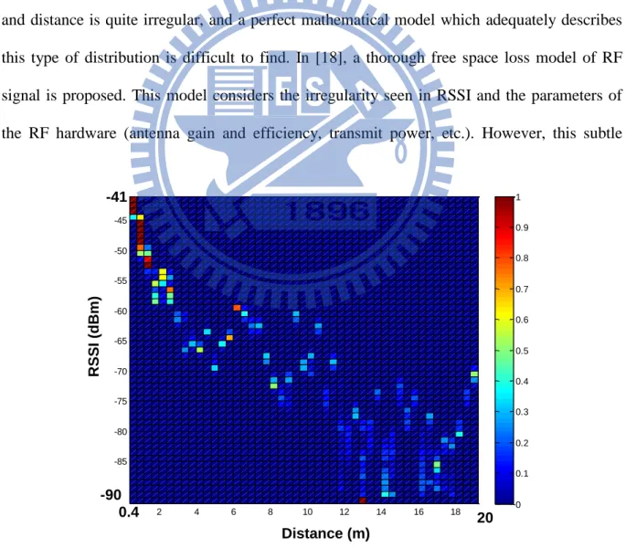
challenging problem is how to overcome the irregularity of range estimation using RSSI. Ramadurai and Sichitiu proposed to merge all the data collected and estimate the probability distribution of WiFi radio frequency (RF) signal strength as a normal distribution function of distance [17]. While their results indicate that the actual position of a signal node is well bounded by the estimated position obtained despite ranging inaccuracies, their method is not suitable for an indoor environment because of the presence of multipath fading. With lower power, stronger shadowing and fading effects, it is even more difficult to find a proper distribution for ZigBee-based systems. Fig. 1-1 shows an example of the relationship between RSSI and distance using ZigBee modules. As the figure shows, the relationship between RSSI and distance is quite irregular, and a perfect mathematical model which adequately describes this type of distribution is difficult to find. In [18], a thorough free space loss model of RF signal is proposed. This model considers the irregularity seen in RSSI and the parameters of the RF hardware (antenna gain and efficiency, transmit power, etc.). However, this subtle
Fig. 1-1: An example of RSSI irregularity.
2 4 6 8 10 12 14 16 18 -90 -85 -80 -75 -70 -65 -60 -55 -50 -45 0 0.1 0.2 0.3 0.4 0.5 0.6 0.7 0.8 0.9 1 Distance (m) RSSI ( dBm ) -41 20 0.4 -90
model assumes that only the direct signal reaches the antenna with the RSSI value, and may still fail in real life situations. Similar observations can also be found in many other attempts [19-21]. When the model fails to accurately describe the relationship between RSSI and distance, overall accuracy will decrease dramatically. Lee et al.[21] used both unscented Kalman filtering (UKF) and particle filtering (PF) to track a target tag with RSSI. The UKF assumes near-linearity and uni-modal Gaussians in the system while the PF does not. Their results show that the assumptions of UKF are very fragile and easily violated. Furthermore, while the tracking method itself is verified, several sets of parameters for the RSSI-model for different parts of the area need to be determined beforehand, to overcome the irregularity.
In summary, the currently available location-aware solutions, whether off-the-shelf or state-of-the-art approaches, suffer from the requirement of prior parameter training and retraining in different application areas. It is difficult or even impossible to build up a location aware system in a totally new environment. This motivated us to develop a new localization method which can provide a straightforward and practical solution for sensor-node calibration and provide WSN localization with acceptable accuracy. The proposed method requires no extra hardware. Most importantly, calibration is only needed once and provides adequate robustness in different environments.
1.2.2
Vision-based Mobile Robot Navigation
Obstacle detection and avoidance are essential for mobile robot navigation. Range-based systems such as ultrasonic sensors and laser scanners are most used sensing devices for environment detection. These ranging systems provide only distance information of the environment, making it difficult to distinguish between an obstacle and a target object, with which the robot would need to interact in many applications. On the contrast, vision-based environment detection systems provide rich information for mobile robot navigation, as long as
the illumination is sufficient in the environment. They have become promising alternatives considering the availability of low-cost image sensors and high-performance computing hardware. Various vision-based approaches, including omnidirectional cameras, stereo and RGB-depth cameras have been widely studied for environment detection, due to their wide view angles or the ability to estimate depth information. However, their specific hardware structures raise problems of price and system complexity and thus limit their applications. Monocular vision-based approaches, on the other hand, do not require special camera configuration. They are considered to be more suitable for cost-effective robotic applications.
Lacking depth information, many monocular vision-based approaches detect objects or obstacles with prior assumptions over the environment. For instance, color cue is commonly used to segment an obstacle or non-obstacle in an image frame [22]. Chen et al. [23] a applied moving object tracking techniques to find obstacles which have significant differences in motion. However, these approaches can only be applied to limited scenes. Optical flow, on the other hand, is a more general approach, which can be used to estimate time-to-collision of obstacles, or the environmental structure from motion (SFM) [24-25]. The computational load of optical flow is rather high, but the robustness against disturbance is still questionable. Recently, some researchers have proposed to use machine learning approaches to obtain depth or structural information using merely monocular cues from single view [26-27]. Although their results are quite impressive in many cases, the outcome is not predictable and stable enough.
Since detecting obstacles in a general manner is still challenging, many researchers propose to reduce the problem to ground detection in a road scene or indoor environments [28-31], with an assumption of ground planarity. The assumption assumes that the ground is always parallel to the robot's motion. Although this assumption may fail in certain environments such as wheelchair ramps or auditoriums, it is still valid in many common indoor
environments. Under this assumption, features on the ground can be modeled and tracked using projective invariants or homography matrix. Among many successful tools, Liang et al. [28] proposed to use reciprocal-polar (RP) image rectification and ground plane segmentation by sinusoidal model fitting in RP-space to segment the ground plane from a mobile robot’s visual field of view. Furthermore, the height of off-ground plane features can also be measured. Zhou et al. [29-30]derived constraints that the homography of the ground plane must satisfy, and then used these constraints to design algorithms for detecting the ground plane by assuming that the camera is fixed on the robot platform and can at most rotate horizontally. Conrad and Desouza use EM Algorithm to classify the features, and achieve an almost perfect detection rate (over 99%) despite the relatively higher number of errors in pixel correspondence [31]. The feature detection and ground model can then be used directly to control the robot or further ground region detection.
As for ground region detection, pixel-level obstacle representation such as warping or inverse perspective transform (IPT) techniques has been widely studied in both stereo-based and monocular-based approaches [32-37]. This technique uses ground plane homography to warp one of the acquired images. Therefore, only pixels which correspond to the ground plane will match in both images. This discrepancy can then be detected by image subtraction and thresholding. Yamaguchi et al. [35] estimate relevant parameters for camera motion as well as the 3D road plane from correspondence points between successive images. The road region is determined by first estimating the ground homography matrix and warping the image of previous frames. In their method, while subtraction is a simple and effective method to detect pixel-wise floor regions, it suffers from some limitations. Due to the nature of subtraction method, textureless obstacles cannot be detected since no discrepancy can be observed even under erroneous projection. Similarly, part of the obstacles may be projected into the floor region and cause some floor areas to be recognized as obstacles. Nevertheless, textureless
obstacles are also difficult to detect using feature-based methods. These problems become more significant in indoor environments due to the common appearance of mono color walls, and need to be resolved for practical applications.
1.3
Research Objectives
The objective of this thesis is to develop a location aware service system which features a ZigBee WSN and a mobile robot. By integrating these technology, the location-ware system will be able provide not merely location information passively, but also provide on-demand services such as intruder detection and active health care. Take intruder detection as an example, if any intruders or abnormal conditions are detected, the state and location of this alert will be transmitted to the security robot and monitoring center on the WSN. The robot can navigate autonomously to the alarm location using the probability-based localization system. After the robot arrives on the scene, the onboard camera will transmit real-time images to the user via both WiFi and 3G networks. The security guards and end-users can therefore easily determine the exact situation in real time.
In order to deploy the WSN for location aware system, this thesis presents a novel probability-based approach to building a location aware system. With this approach, the inconsistencies often seen in received signal strength indicator (RSSI) measurements are handled with a minimum of calibration. By taking off-line calibration measurement of a ZigBee sensor network, the inherent problem of signal uncertainty of to-be-localized nodes can be effectively resolved. The proposed RSSI-based algorithm allows flexible deployment of sensor nodes in various environments.
This thesis also aims to find a robust method to detect ground plane region in an indoor environment. In particular, the method should be able to deal with textureless and mono color ground and obstacles. The determined ground plane will be further processed to provide range
information for mobile robot obstacle avoidance. The main concept is to integrate multiple visual cues to avoid limitations in image feature extraction and achieve robustness against illumination and camera view variations. First, robust feature extraction and matching methods are adopted for feature extraction and matching to increase both robustness and speed in the homography estimation step. Furthermore, a key-frame selection criterion is proposed to guarantee the estimation is proper and avoid the virtual plane problem caused by zero/near-zero camera translations. To observe ground region pixel-wise, we propose an adaptive self-segmentation and tracking algorithm to find the ground region according to both the feature points and color segments. Applying IPT on the ground-region-segmented image, results in a rectified image, similar to an occupancy grid map. The robot can then use distance information to prevent from colliding with obstacles. The constructed map itself can also be used for many other robot control purposes.
1.4
Organization of the Thesis
The remainder of this thesis is organized as follows: In Chapter 2, the probability-based localization method is first presented. The proposed algorithm guarantees a robust localization method under different environment. The localization result can be applied on robot as well as a user with the ZigBee module In Chapter 3, monocular visual navigation system is presented to provide navigation ability for the robot with merely a camera. Chapter 4 shows the hardware and other sub system implemented for establishing the intelligent environment and the mobile robot system. Experimental results of the proposed are reported and discussed in Chapter 5. Chapter 6 concludes the contributions of this work and provides the recommendations for future research.
Chapter 2.
Probability-based Location Aware Design
2.1
Introduction
For an on-demand robotic system, a locational aware module is required to provide location data of objects of interest, users and of the mobile robot itself. This information supports various intelligent behaviors of a service robot in day-to-day scenarios. In this thesis, a novel probability-based approach to building up a location aware system is presented. In this approach, the uncertainties and inconsistencies often seen in received signal strength indicator (RSSI) measurements are handled with a minimum of calibration. By taking off-line calibration measurement of a ZigBee sensor network, the inherent problem of signal uncertainty of to-be-localized nodes can be effectively resolved. The proposed RSSI-based algorithm allows flexible deployment of sensor nodes in various environments. The proposed algorithm has been verified in several typical environments. The rest of this chapter is organized as follows: In section 2.2 the proposed probabilistic localization method is presented. The performance evaluation of the localization system are described and discussed in session 2.3.
2.2
Proposed ZigBee Localization Method
To overcome limitations posed by uncertainties of RSSI, we suggest a novel probability-based approach to estimating location by modeling the RSSI vs. distance relationship with discrete probability density functions. This approach aims to provide a straightforward method of describing different distributions without losing generality. While
most current approaches use mathematical equations to model the RSSI vs. distance relationship, the proposed method adopts the original RSSI vs. distance data to construct its own model. Furthermore, instead of using trilateration or fingerprint techniques, the location is estimated by accumulating a probability histogram observed from several reference nodes on a local probability map. This approach will be shown to have better tolerance against fluctuations and inconsistencies inherent with the RF signal. It is also flexible because it uses the available number of the RSSI measurements and the deployment of ZigBee nodes.
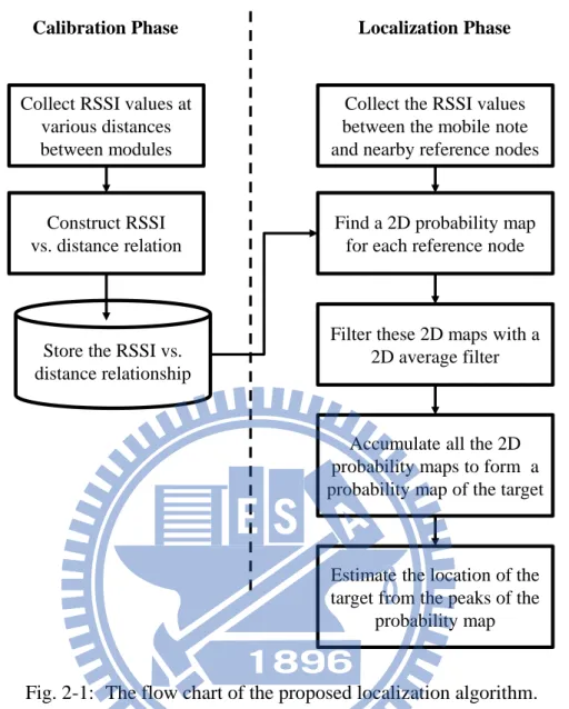
We first assume that the locations of all reference nodes are already known and the RSSI between each pair of nodes can be received. Fig. 2-1 shows a flow chart of the algorithm. It contains a calibration phase which models the RSSI vs. distance relationship and a localization phase which estimates the location using a filtered 2D probability map as follows.
2.2.1
Modeling of RSSI vs. Distance Relationship
The calibration phase estimates the distance between nodes based on the RSSI measurement. Instead of using a mathematical path-loss model, the RSSI vs. distance relationship is collected and modeled with a series of probability histograms, which record different distances measured under a fixed RSSI. The histogram therefore represents the discrete probability density function (pdf) of a given RSSI value. Let R and D denote the random variables of the RSSI reading and distance between nodes (in meters), respectively. Assume the model is tested from distance 0 to L meters at intervals of q meters. The pdf of the RSSI value equal to r can be defined as:
1 1 i i+1 0 0 P | =r = P d d | =r N N D i i i D R D R h
where di represents the distance of the ith interval, N = L/q is the total bins in the histogram and
= –88 dBm. This model can easily be implemented onboard the sensor node since it only needs a single look-up table. Clearly, the number of the bins in each histogram limits the resolution of the estimation of distance. This is, however, not critical since the RSSI value is also discrete in practice.
2.2.2
2D Probability Map
In the next step, the location of the mobile node is estimated using the RSSI values measured from several nearby reference nodes. The concept is to apply the two-dimensional multi-lateration method with the estimated pdfs. A trilateration method determines the location by finding the intersections of circles given from (1) the centers of the reference nodes; and (2)
Fig. 2-1: The flow chart of the proposed localization algorithm.
Collect RSSI values at various distances between modules
Collect the RSSI values between the mobile note and nearby reference nodes
Find a 2D probability map for each reference node
Filter these 2D maps with a 2D average filter
Accumulate all the 2D probability maps to form a probability map of the target
Calibration Phase Localization Phase
Store the RSSI vs. distance relationship
Construct RSSI vs. distance relation
Estimate the location of the target from the peaks of the
distance between the mobile node and several reference nodes (more than three). In the proposed algorithm, however, a mobile node may obtain several possible distance measurements from each reference node. The next step is to find the intersection sets of distance measurements with the largest probability from several reference nodes.
To simplify the calculations, the proposed algorithm estimates the 2D probability distribution directly on the 2D map quantized in grids of a fix size of K × K. Specifically, grids of the size N × M are spanned over the localization area, defined by (x,y), 1 x N and 1 y
M. The next step is to derive the location of the mobile node xm = (xm, ym) from a RSSI vector
R = (R1, R2…, Ri, … RK), containing the RSSI values received from K reference nodes with
known positions xr,i, 1 i K. For each reference node xr,i with a RSSI value r measured at
the mobile node, the 2D pdf P(x,y,i) of the mobile node at position (x,y) can be given as:
N , i 1 1 N , i 1 1P( , , )
P
( , ) | R = r
P
(
( , )) | R = r
M X Y m y x M r i y xx y i
x y
D
x y
x
x
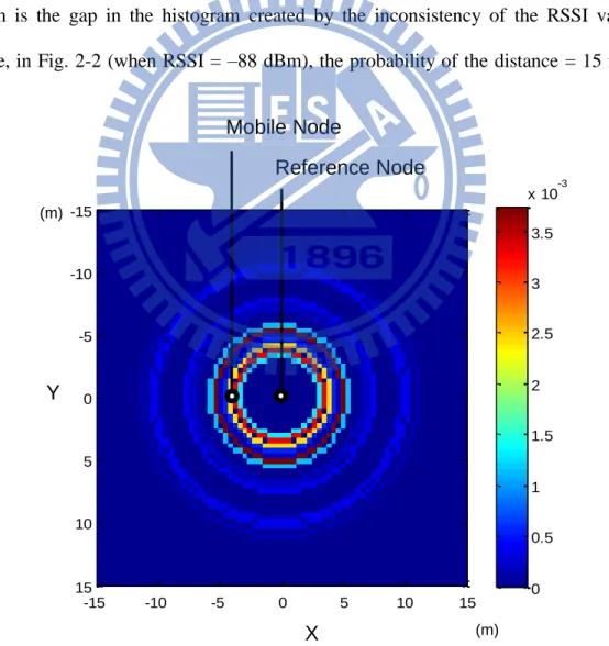
Since the RSSI vs. distance model is known and modeled as a 1D pdf, the 2D probability distribution is equivalent to a repeat of the 1D pdf P(D |R = r) in (1) around the coordinates of the reference node from 0 to 360 degree. Fig. 2-3 shows a graphical example of the 2D pdf with one mobile node and one reference node at (0,0). The 2D pdf indicates the probability of the mobile node by means of a 2D probability map.
2.2.3
Filtered 2D Probability Map
While the localization method described in the previous section works under many circumstances, some practical issues still need to be resolved. Among them, the most important problem is the gap in the histogram created by the inconsistency of the RSSI values. For instance, in Fig. 2-2 (when RSSI = –88 dBm), the probability of the distance = 15 m is zero,
Fig. 2-3: The 2D pdf of a fixed RSSI reading between a reference node and a mobile node. -15 -10 -5 0 5 10 15 -15 -10 -5 0 5 10 15 0 0.5 1 1.5 2 2.5 3 3.5 x 10⁻³ Reference Node Mobile Node X Y (m) (m)
which is unlikely in reality, because of the irregular nature of the radio signal. To realize the goal that “the model only needs to be built once,” we need to enhance the proposed model to tolerate these circumstances. Furthermore, for some WSN applications such as searching, it would also be beneficial if the proposed method can provide alternative locations when it fails on the first try. In order to resolve these issues, we treat the 2D probability map as an image and apply a 2D circular averaging filter H(x,y) with radius r to it. The idea is to smooth the map by filling the gaps and avoid any zero probability on the map by taking probabilities of nearby areas into account. The filter is defined as:
otherwise
,
0
if
,
1
1
)
,
(
2 2 2 2r
y
x
r
y
x
H
where the value of r is adjusted according to the variance of the RSSI values. The filtered map is thus stated as:
P
(
x
,
y
,
i
)
P
(
x
,
y
,
i
)
H
(
x
,
y
)
As a result, the filtered map provides a relatively more robust result than the raw map (refer to the experiment section). The filtered map also provides other possible locations for the robot or human to search for the target, if they failed to find the target at the location with the highest probability.
2.2.4
Location Estimation
Finally, the location of the current mobile node will be estimated by accumulating all the 2D probability maps obtained from reference nodes such that:
K ii
y
x
P
y
x
P
1)
,
,
(
)
,
(
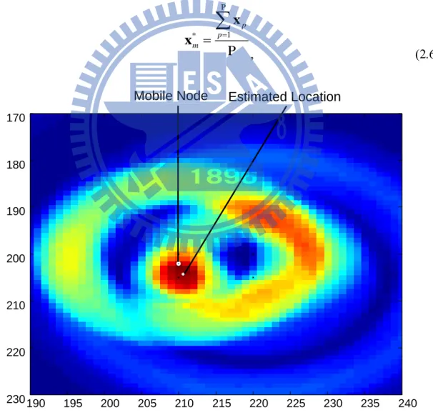
The summation of each grid P (x,y) is analogous to the convolution of all the individual distributions. Fig. 2-4 shows an example of how maps obtained from different reference nodes are accumulated into the final map. As a result, the mobile node is located by the peak value of the probability map, even though the upper-right map suggests a false result. However, because of the natural irregularities of the RSSI, the results may lead to a map with several peaks. The location of the mobile node will not be determined by one of the peaks under those circumstances. Instead, the propose algorithm determines the location by estimating the geometric center of all the peaks such that:
P 1 * P p p m
x x Fig. 2-4: An example of how filtered 2D maps obtained from different reference nodes are combined into the final map.
190 195 200 205 210 215 220 225 230 235 240 170 180 190 200 210 220 230 Estimated Location Mobile Node
where xp denotes location of the pth peak on the 2D pdf, 1 p P. Note that the
multi-lateration method can now be treated as a special case of the proposed algorithm, where the pdf of each reference node is an impulse function.
2.3
Robustness Test of The Proposed Localization Algorithm
The experiment aims to test if the proposed method can handle ZigBee localization in different environments more robustly than other methods. Three localization methods: Min-max, ROCRSSI, and CC2431 are compared with the proposed method in this experiment. Min-Max is a widely-adopted range-based localization method [7]. The technique known as Ring Overlapping based on Comparison of Received Signal Strength Indication (ROCRSSI) is a commonly used range-free approach [8] to localization. The CC2431 location engine is embedded in a Texas Instruments CC2431 system-on-chip (Soc) solution for ZigBee/IEEE 802.15.4 wireless sensor networks. CC2431 implements Motorola’s IEEE 802.15.4 radio– location solution exploiting a maximum likelihood estimation algorithm [6]. To compare the CC2431 location engine with the proposed method, we have adopted our modules with CC2431 chips to perform the experiment.
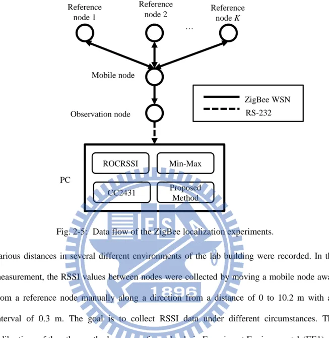
Fig. 2-5 shows the data flow of the experimental system. RSSI values of reference nodes were first estimated by the mobile node. The values were then sent to the observation node and finally transmitted to the host PC via a serial link. The collected RSSI values were then estimated with different algorithms and compared with ground truth. Three experiments have been performed in three different types of environments. Table 2-1 shows the configurations of these environments. The localization result using raw data as well as the filtered 2D map were individually tested in the experiment to further investigate the effectiveness of the proposed method. Fig. 2-6 , Fig. 2-7 and Fig. 2-8 provide photos and the locations of beacons in these environments. During the calibration measurements of the proposed method, RSSI values at
various distances in several different environments of the lab building were recorded. In the measurement, the RSSI values between nodes were collected by moving a mobile node away from a reference node manually along a direction from a distance of 0 to 10.2 m with an interval of 0.3 m. The goal is to collect RSSI data under different circumstances. The calibrations of the other methods were performed only in Experiment Environment 1 (EE1). In the experiments, every ZigBee module was fully charged before the experiment, since the power of ZigBee sensor nodes affects RSSI and hence the location prediction.
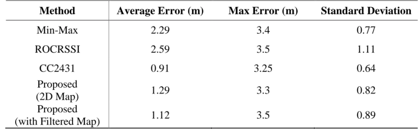
Table 2-1 shows the overall localization results of EE1. The results show practically no difference in the localization error between the proposed method and the CC2431 localization engine. Both results outperform the Min-Max and ROCRSSI methods, which is similar to the results reported in [7]. Notice that the parameters of the signal propagation model used in the CC2431 localization engine are given to maximize the accuracy of the experiment, while our approach uses the sensor model established beforehand from other calibration places. In
Fig. 2-5: Data flow of the ZigBee localization experiments. Reference node 1 Reference node 2 … Mobile node Observation node PC ROCRSSI Min-Max Proposed Method CC2431 ZigBee WSN RS-232 Reference node K
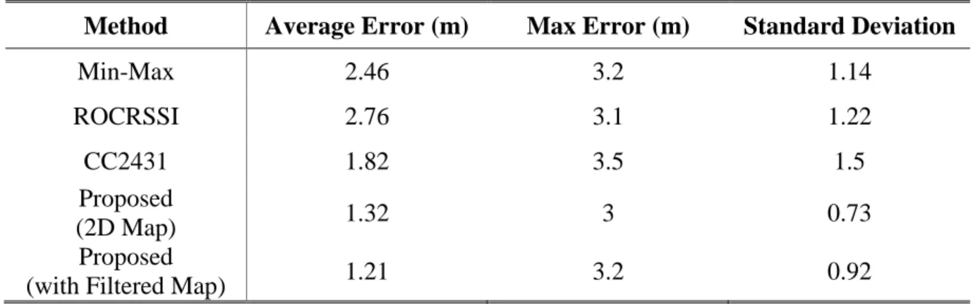
Experiment Environments 2 (EE2) and 3 (EE3), the same RSSI models and parameters were applied as were used in EE1. Tables III and IV show the overall localization error of the experiments in EE2 and EE3, respectively. Since these two environments are different from the test in EE1, the RSSI-based localization models of the other methods are no longer suitable. As a result, other methods perform more poorly in the new environments. On the contrary, the proposed method already considers possible changes in the environment and preformed more robustly in different environments.
2.4
Summary
This chapter presents a novel method for localizing a ZigBee node in a WSN. The probability-based approach takes the uncertainties of RSSI-based distance estimation into account. The method is independent of the sensor node distribution and environment configuration and therefore can minimize the calibration burden in practical applications. The performance of the proposed algorithm has been evaluated by experiments in three different environments. The experimental results show that the average error of the implemented location aware system is 1.7 m, despite a much higher range uncertainties from raw RSSI values. This accuracy can effectively support service robotic applications, especially when properly combined with a vision system. For instance, the localization system can provide a possible area of a user calling the robot for service or when an emergency situation occurs.
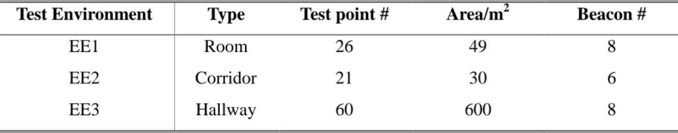
Table 2-1: Configurations of Test Environments
Test Environment Type Test point # Area/m2 Beacon #
EE1 Room 26 49 8
EE2 Corridor 21 30 6
(a)
(b)
Fig. 2-6: (a) Experimental environment 1 (EE1): the lab 622 and corridor (b) the location of deployed ZigBee beacons in the experiment (filled circles).
Table 2-2: Estimation Error Comparision: EE1
Method Average Error (m) Max Error (m) Standard Deviation
Min-Max 2.29 3.4 0.77 ROCRSSI 2.59 3.5 1.11 CC2431 0.91 3.25 0.64 Proposed (2D Map) 1.29 3.3 0.82 Proposed
(with Filtered Map) 1.12 3.5 0.89
Corridor LAB 622 RN1 (0, 0) RN3 (0, 6) RN5 (3.5, 0) RN7 (3.5, 5) RN2 (2.25, 2) RN4 (2.25, 8) RN6 (6, 2) RN8 (6, 7)
(a)
(b)
Fig. 2-7: (a) Experiment Environment 2 (EE2): the corridor of lab building, (b) the location of deployed ZigBee beacons in the experiment (filled circles).
Table 2-3: Estimation Error Comparision: EE2
Method Average Error (m) Max Error (m) Standard Deviation
Min-Max 2.46 3.2 1.14 ROCRSSI 2.76 3.1 1.22 CC2431 1.82 3.5 1.5 Proposed (2D Map) 1.32 3 0.73 Proposed
(with Filtered Map) 1.21 3.2 0.92
(0,0) (0,4)
(4,4)
(8,4) (8,0)
(a)
(b)
Fig. 2-8: (a) Experiment Environment 3 (EE3): the lobby of the lab building (b) the location of deployed ZigBee beacons in the experiment (filled circles).
Table 2-4: Estimation Error Comparision: EE3
Method Average Error (m) Max Error (m) Standard Deviation
Min-Max 3.7 6.3 1.29 ROCRSSI 3.1 5.2 1.61 CC2431 2.2 7.58 1.74 Proposed (2D Map) 1.5 4.2 0.89 Proposed
Chapter 3.
Monocular Visual Navigation Design
3.1
Introduction
Obstacle detection and avoidance are essential for mobile robot navigation. This chapter proposed a monocular vision-based obstacle avoidance design for mobile robot navigation. A novel image processing procedure is developed to estimate the distance between the robot and obstacles based-on inverse perspective transformation (IPT) in an image plane. A robust image processing solution is proposed to detect and segment a drivable ground area within the camera view. The proposed method integrates robust feature matching with adaptive color segmentation for plane estimation and tracking to cope with variations in illumination and camera view. After IPT and ground region segmentation, distance measurement results are obtained similar to those of a laser range finder for mobile robot obstacle avoidance and navigation. The merit of this algorithm is that the mobile robot can have the capacity of path finding and obstacle avoidance by using a single monocular camera. The rest of this chapter is organized as follows: The concept of the system is described in section 3.2. Section 3.3 goes through the detailed algorithm of ground plane and obstacle detection. The calibration experiment of distance measurement is presented in section 3.4. Section 3.5 shows the simulation result using synthetic images. Experimental results using mobile robot will be reported in Chapter 5.
3.2
System Overview
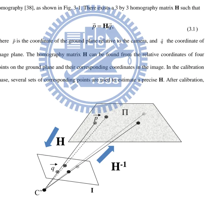
In order to estimate range information for mobile robot navigation control using merely monocular image sequence, the basic idea is to find the world coordinates of pixels belongs to the ground plane from the image plane by applying IPT. For common indoor environments, we can make the following assumptions: (1) the ground is a plane; (2) the robot moves parallel to the ground; and (3) the camera is fixed on the robot. The distance between the camera and the ground plane is thus fixed and the IPT of the ground plane can be determined beforehand. With the pinhole camera model, applying IPT can be simplified by using plane-to-plane homography [38], as shown in Fig. 3-1. There exists a 3 by 3 homography matrix H such that
p
H
q
,
where pis the coordinate of the ground plane relative to the camera, and q the coordinate of image plane. The homography matrix H can be found from the relative coordinates of four points on the ground plane and their corresponding coordinates in the image. In the calibration phase, several sets of corresponding points are used to estimate a precise H. After calibration,
Fig. 3-1: Homography of coplanar points between image plane and ground plane.
p
C’
I
H
H
-1
the projected images can then provide the relative position of each pixel on the ground in world coordinates [33,34]. Off-ground objects, on the other hand, will be distorted after the transformation. A recalibration will be necessary if the position or angle of the camera is changed.
Due to the assumptions, IPT can only map pixels on the ground plane. In practical obstacle avoidance applications, pixels which belong to the ground plane must be found on the fly in order to determine distance to obstacles. The proposed system therefore aims to solve this problem via multiple visual clues. Fig. 3-2 illustrates the architecture of the proposed monocular visual navigation system (MonoVNS). In this design, two parallel procedures are launched simultaneously after the image preprocessing step. In the ground feature detection process, the system extracts all the features in current image at time step t, and matches them to features observed in previous N frames. N is determined by the frame number that can be processed in one second. According to the correspondence and pre-determined ground features, ground homography and features on the ground in the newly acquired image can be found. The system then uses the homography matrices among consecutive frames to classify all other features as on the ground or not. Meanwhile, in a parallel process, images are segmented into patches according to their color homogeneity. These segments are then classified into ground or off-ground regions by comparing with warped images. The detailed algorithm is described in Section 3.3.
Once the ground and off-ground areas are segmented, the coordinates of the ground area (relative to the camera) can be estimated by applying IPT to the acquired images. The images are virtually rectified with a downward-looking pose. The range information can then be obtained by a ray-casting operation. Ray casting is a procedure to mimic a laser range finder (LRF) using the rectified image. A set of virtual rays are casted from the camera center, one per pixel, until the pixel belongs to an off-ground area, as shown in Fig. 3-3. The distance of a
Fig. 3-2: The architecture of the proposed MonoVNS. R o b u s t F e a tu re E x tr a c ti o n F e a tu re M a tc h in g G ro u n d F e a tu re D e te c ti o n G ro u n d P la n e R e g io n S e g m e n ta io n R o b u s t H o m o g ra p h y E s ti m a ti o n In v e rs e P e rs p e c ti v e T ra n s fo rm a ti o n Im a g e S e g m e n ta ti o n S e g m e n t c o m p a ri s o n G ro u n d /n o n -g ro u n d s e g m e n t c la s s if ic a ti o n R a y C a s ti n g O b s ta c le D e te c ti o n R o b o t N a v ig a ti o n C o n tr o ll e r G ro u n d /n o n -g ro u n d r e g io n l a b e le d i m a g e Im a g e s e g m e n ts S U R F p o in ts G ro u n d / N o n -g ro u n d f e a tu re s Im a g e s e g m e n ts Ra n g e d a ta G ri d m a p M a tc h e d f ra m e s a n d fe a tu re p a ir s G ro u n d / N o n -g ro u n d f e a tu re s C la s s if ic a ti o n r e s u lt M o n o c u la r C a m e ra Im a g e s e q u e n c e
ray to an object can thus be estimated by the two-norm of the pixel. The distances of these rays
now represent the distances to obstacles, just like a typical LRF, but with a smaller view angle. This information can be applied to any LRF-based obstacle avoidance scheme, and make it to work in a similar manner.
3.3
Ground Plane and Obstacle Detection
3.3.1
Ground Feature Detection
In order to obtain robust matching results of corresponding points, the feature extractor should have properties such as invariance to rotation, scale, illumination and image noise. In previous related works, Harris and FAST [39] corner detectors have been widely adopted [28-31]. The robustness of these descriptors is relatively limited in practical applications. In last decade, there have been many advances in scale/rotation-invariant feature extractors, such as Scale-Invariant Feature Transform (SIFT) [40]. A An array of image gradient histograms has been used as a descriptor instead of a raw image patches. However, the heavy computation
Fig. 3-3: An example of ray casting in an image after IPT. The white area indicates the ground region. The dark area indicates obstacles. The distances between the camera center
and obstacles can be estimated by measuring the length of the rays. Camera center
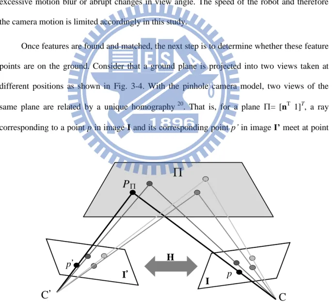
load of SIFT algorithm makes it unsuitable for real-time navigation applications. In this work, a combination of robustness and execution speed has been investigated. In the current design, the FAST corner detector is first applied to find interesting feature points. These points will be further described with Speeded Up Robust Features (SURF) [41] for its superior robustness and execution speed. FAST provides a high speed corner detection performance, which can reach full-frame feature detection up to 400Hz. While the robustness can be preserved, SURF is about three times faster than SIFT in feature extraction step. SURF also provides an indexing value for fast matching purpose. Nevertheless, these methods may still fail under excessive motion blur or abrupt changes in view angle. The speed of the robot and therefore the camera motion is limited accordingly in this study.
Once features are found and matched, the next step is to determine whether these feature points are on the ground. Consider that a ground plane is projected into two views taken at different positions as shown in Fig. 3-4. With the pinhole camera model, two views of the same plane are related by a unique homography 20. That is, for a plane = [nT 1]T, a ray corresponding to a point p in image I and its corresponding point p’ in image I’ meet at point
Fig. 3-4: Homography of coplanar points observed from two images. p
p’
C’
C
I’
IH
P
P in plane . Therefore, if a set of coplanar points pi with homogeneous image coordinates
(xi, yi, 1)T are found, and their correspondences {pi p'i} in two images are also found, there
exists a 3 by 3 homography matrix H such that
pipi Hpi 1 ) 1 ( K R tn K H T d
where K is the intrinsic camera parameter matrix, R is the rotation matrix, t is the translation vector, is the scale factor, and d is the distance between the plane and the camera. To determine H, four non-degenerated corresponding points are required since each point correspondence provides two independent constraints. In the proposed system, the features on the ground are initially determined, i.e., a subset of pi is known as on the ground plane. The
homography of the ground plane can thus be determined initially. To further reduce possible matching errors, we apply RANdom SAmple Consensus (RANSAC) to eliminate outliers and robustly determine H [42-43]. Note that the H matrix here is only relevant to find a robust plane relationship between two frames. It does not affect the homography matrix applied in IPT computation. Once the homography matrix is determined, the rest of the corresponding points can also be determined if it is on the ground by using the back projection technique such that:
otherwise
threshold
p
p
p
i i i,
ground
-off
if
ground,
H
The factor of determining the threshold depends on how accurate the ground feature classification should be. Since the mobile robot can run over certain small obstacles, there is a small range of tolerance for the feature classification. This facilitates the mobile robot to navigate on somewhat uneven surfaces. A fixed value is determined beforehand in the current