在直接平行指令集運算架構中處理失速週期
57
0
0
全文
(2) 在直接平行指令集運算架構中處理失速週期 Handling Stall Cycles in EPIC Architecture. 研 究 生:顏先駿. Student: Hsien-Chun Yen. 指導教授:鍾崇斌. Advisor: Chung-Ping Chung. 國立交通大學 資訊工程學系 碩士論文. A Thesis Submitted to Department of Computer Science and Information Engineering College of Electrical Engineering and Computer Science National Chiao Tung University in partial Fulfillment of the Requirements for the Degree of Master in. Computer Science and Information Engineering. June 2004 Hsinchu, Taiwan, Republic of China. 中華民國九十三年六月.
(3) 在直接平行指令集運算架構中處理失速週期 學生:顏先駿. 指導教授:鍾崇斌 博士. 國立交通大學資訊工程學系碩士班. 摘. 要. 由於處理器效能不斷的提升,與記憶體、週邊裝置間的速度差距也愈 來愈大。有一些指令,會因為快取記憶體失誤 (cache miss) 或執行延遲等 原因,造成該指令的執行時間,會依照執行當時的運算子、狀態等而有所 不同。這些指令在編譯時期無法預測執行時間,做出最佳的靜態排程 (static scheduling)。而執行時期發生失速 (stall) 的情況,會直接影響整個系 統的效能。於是,我們需要一個好的動態執行機制。 在這篇論文中,我們針對直接平行指令集運算 (EPIC) 架構,提出一個 方法來處理失速的問題。我們在每一道指令 (instruction) 前面,額外增加 硬體動態執行機制所需要的提示,並且在程式可能發生無法預測執行時間 的指令和其相關指令上標記該提示,使得處理器得以直接利用標記的資 訊,不需外加複雜的硬體來做煩冗的相依性檢查,即可打破指令群 (instruction group) 的執行順序限制,正確執行程式,並且達成動態執行的 效果。將失速的週期與不同的失速週期重疊,或把被阻擋而未完成的指令 與其他指令一起執行,即可隱藏失速所造成的影響,進而增進處理器的效 能。. -i-.
(4) Handling Stall Cycles in EPIC Architecture Student: Hsien-Chun Yen. Advisor: Dr. Chung-Ping Chung. Department of Computer Science and Information Engineering National Chiao Tung University. ABSTRACT There are many types of stalls. Some instructions have unpredictable execution latencies because of stall occurred. It is impossible at compile time to identify all possible sources of stalls and their durations. Also, it is impossible to give an optimized instruction scheduling at compiler time. When executing a program, stalls may occur and break down the performance. So, a good dynamic scheduling execution mechanism is necessary. In this thesis, we introduce an approach for an EPIC architecture to become an out-of-order execution architecture. Instead of additional complex hardware, we attach several bits to each instruction to show hardware how to execute program dynamically without hazard detection and instruction scheduling circuit. Stall cycles can overlap with other stall cycles and the blocked instructions can be executed with non-blocked instructions. When the stall cycles are hidden, the total execution time can be reduced and archive performance improvement.. - ii -.
(5) 誌. 謝. 首先感謝我的指導老師 鍾崇斌教授,在老師的諄諄教誨、辛勤指導 與勉勵下,得以順利完成此論文。老師除了給我學業上的指導外,也告訴 我許多與人相處的智慧。 我也要感謝本實驗室的另一位大家長,也是我的口試委員. 單智君教. 授,單老師在我的碩士生涯當中,給了我許多寶貴的指導。同時我也感謝 另一位口試委員 金仲達教授,由於老師們的建議和指正,使得這篇碩士 論文能夠更加完整。 感謝實驗室的同學們,大家每次都不厭煩地與我討論,告訴我論文的 不足之處,給我非常大的幫助。 最後我要感謝我的父母以及我的女友,由於你們無時無刻的支持我、 勉勵我,我才得以順利完成此論文。 謝謝你們!. 顏先駿 2004 年 6 月. - iii -.
(6) Table of Contents 摘. 要 .......................................................................................... i. ABSTRACT......................................................................................... ii 誌. 謝 ........................................................................................ iii. Table of Contents................................................................................ iv List of Figures..................................................................................... vi List of Tables .................................................................................... viii Chapter 1 Introduction ......................................................................... 1 1.1 Instruction-Level Parallelism ...........................................................................................1 1.2 Stall Reasons ....................................................................................................................2 1.3 Cycle Accounting .............................................................................................................2 1.4 Motivation ........................................................................................................................4 1.5 Objective...........................................................................................................................5 1.6 Organization of this Thesis...............................................................................................5. Chapter 2 Background ......................................................................... 6 2.1 Overview of Multiple-Issue Processors............................................................................6 2.2 Explicitly Parallel Instruction Computing (EPIC) ...........................................................8 2.3 Dynamic Execution ........................................................................................................11 2.3.1 Dynamic Scheduling................................................................................................11 2.3.2 Register Renaming Issue on Predicated Code .........................................................13 2.4 Related Work..................................................................................................................14 2.4.1 Advanced Load........................................................................................................15 2.4.2 Out-of-order Execution Itanium Processor..............................................................16. Chapter 3 Design of Out-of-order Execution Mechanism ................. 18 3.1 Concept...........................................................................................................................18 3.1.1 The Stall Problem of Instruction Groups.................................................................20 3.1.2 Observation..............................................................................................................20. - iv -.
(7) 3.2 Dependency Control.......................................................................................................22 3.2.1 Dependency Bit .......................................................................................................22 3.2.2 Hardware Modification............................................................................................23 3.3 Dependency Bit Marking Method ..................................................................................25 3.4 Example..........................................................................................................................31. Chapter 4 Simulation Environment and Result.................................. 40 4.1 Simulation Environment.................................................................................................40 4.1.1 IA-64 Simulator .......................................................................................................40 4.1.2 IA-64 Compiler........................................................................................................42 4.1.3 Benchmarks .............................................................................................................42 4.2 Simulation Results and Analysis ....................................................................................42. Chapter 5 Conclusions and Future Works ......................................... 45 5.1 Conclusions ....................................................................................................................45 5.2 Future Works ..................................................................................................................46. References.......................................................................................... 47. -v-.
(8) List of Figures Figure 1.1: Itanium Processor Family Cycle Accounting ..........................................................4 Figure 2.1: Renaming issue ......................................................................................................14 Figure 3.1: A program's control-data-flow graph and its EPIC representation ........................19 Figure 3.2: One instruction stall occurred, whole instruction group stall. ...............................19 Figure 3.3: In-order execution vs. out-of-order execution .......................................................21 Figure 3.4: Dependency bits.....................................................................................................22 Figure 3.5: General EPIC block diagram .................................................................................23 Figure 3.6: Proposed EPIC architecture with dependency control block.................................24 Figure 3.7: Detail of the dependency control ...........................................................................25 Figure 3.8: Step 1: Mark all instructions which may cause stall..............................................26 Figure 3.9: Step 2: Mark all continuous instructions needed to be blocked when that stall occurred. .......................................................................................................................27 Figure 3.10: Step 3: Mark the first instruction with data dependence after the continuous dependency chain. ........................................................................................................28 Figure 3.11: Discard the redundant dependency bit. ................................................................29 Figure 3.12: Merge two dependency bit without overlap.........................................................30 Figure 3.13: Merge two dependency bit with overlap..............................................................30 Figure 3.14: The 1st clock cycle. There are 3 function units and 8 slot of instruction bundle queue.............................................................................................................................31 Figure 3.15: The 2nd clock cycle. ............................................................................................32 Figure 3.16: The 3rd clock cycle. .............................................................................................32 Figure 3.17: The 4th clock cycle. .............................................................................................33 Figure 3.18: The 5th clock cycle. .............................................................................................33 Figure 3.19: The 6th clock cycle. A marked instruction can be executed if no stall instructions with the same mark in the function units. When execute a marked instruction, the executable status of all continuous instructions are set. ...............................................34 Figure 3.20: The 7th clock cycle. A stall occurred...................................................................34 Figure 3.21: The 8th clock cycle. The blocked instructions are skipped at this time. Note that these two instructions can be executed at the same time because they belong to the same instruction group. A branch mispredict occurred at this clock cycle. .................35 Figure 3.22: The 9th clock cycle. .............................................................................................35 Figure 3.23: The 10th clock cycle. ...........................................................................................36 Figure 3.24: The 11th clock cycle. ...........................................................................................36 Figure 3.25: The 12th clock cycle. ...........................................................................................37 - vi -.
(9) Figure 3.26: The 13th clock cycle. No instruction can be executed until the stall instruction completed......................................................................................................................37 Figure 3.27: The 14th clock cycle. The stall instruction is completed. Blocked instructions in the queue can be executed now. ...................................................................................38 Figure 3.28: The 15th clock cycle. ...........................................................................................38 Figure 3.29: The 16th clock cycle. Set the executable status of next continuous marked instructions....................................................................................................................39 Figure 3.30: The 17th clock cycle. ...........................................................................................39 Figure 4.1: The length of continuous instructions after each stall instruction. ........................43 Figure 4.2: Simulation Results .................................................................................................43. - vii -.
(10) List of Tables Table 2.1: The five primary approaches in use for multiple-issue processors and the primary characteristics that distinguish them...............................................................................7 Table 4.1: The five execution unit slots in the IA-64 architecture and what instructions type they may hold are shown. .............................................................................................41. - viii -.
(11) Chapter 1 Introduction In this chapter, we introduce an overview of instruction-level parallelism, stalls, and cycle accounting. Then we give the research motivation and objective of this thesis. At last, the organization of this thesis is introduced.. 1.1 Instruction-Level Parallelism All processors since about 1985, including those in the embedded space, use pipelining to overlap the execution of instructions and improve performance. This potential overlap among instructions is called instruction-level parallelism (ILP) since the instructions can be evaluated in parallel. Because of the limitation imposed by data and control dependences, the processor cannot exploit parallelism unlimited. There are two largely separable approaches to exploiting ILP. One approach covers techniques that are largely dynamic and depend on the hardware to locate the parallelism. The other approach focuses on techniques that are static and rely much more on software. In practice, this partitioning between dynamic and static and between hardware-intensive and software-intensive is not clean, and techniques from one camp are often used by the other. The techniques of exploiting ILP to increase performance are the key to achieving rapid performance improvements. The question of how much ILP exists is critical to our long-. -1-.
(12) term ability to enhance performance at a rate that exceeds the increase in speed of the base integrated circuit technology. On a shorter scale, the critical question of what is needed to exploit more ILP is crucial to both computer designers and compiler writers.. 1.2 Stall Reasons If an instruction can not be executed smoothly in expected way or expected cycle counts, it calls ‘stall’. There are many stall reasons, such as memory access cycles, cycles spent flushing the pipe due to branch mispredicts, cycles spent flushing the pipe due to interrupts and exceptions, and etc. It is not possible at compile time to identify all possible sources of stalls and their durations. In a VLIW architecture, suppose a memory access causes a cache miss, leading to a longer than expected stall. If other, parallel, functional units are allowed to continue operating, sources of data dependency may dynamically emerge. For example, consider two operations which have an output dependency. The original scheduling by the compiler would ensure that there is no consequent WAW (write after write) hazard. However, if one stalls and the other ‘runs ahead’, the dependency may turn into a WAW hazard. So if you are serious about getting the compiler to do all dependency resolution, you must stall all elements together. This is a performance problem.. 1.3 Cycle Accounting The first step in any performance analysis is to understand the performance characteristics of the workload under study. There are two fundamental measures of interest: event rates and program cycle break down. [4] •. Event Rate Monitoring: Event rates of interest include average retired instructions per clock, data and instruction cache miss rates, or branch mispredict rates measured -2-.
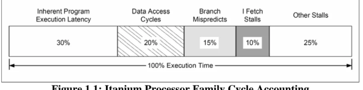
(13) across the entire application. Characterization of operating systems or large commercial workloads (e.g. OLTP analysis) requires a system-level view of performance relevant events such as TLB miss rates, VHPT walks/second, interrupts/second, or bus utilization rates. •. Cycle Accounting: The cycle breakdown of a workload attributes a reason to every cycle spent by a program. Apart from a program’s inherent execution latency, extra cycles are usually due to pipeline stalls and flushes. While event rate monitoring counts the number of events, it does not tell us whether. the observed events are contributing to a performance problem. A commonly used strategy is to plot multiple event rates and correlate them with the measured IPC (instructions per cycle) rate. If a low IPC occurs concurrently with a peak of cache miss activity, chances are that cache misses are causing a performance problem. To eliminate such guess work, a processor can provide a set of cycle accounting monitors, which break down the number of cycles that are lost due to various kinds of microarchitectural events. As shown in Figure 1.1, this lets us account for every cycle spent by a program and therefore provides insight into an application’s microarchitectural behavior. Note that cycle accounting is different from simple stall or flush duration counting. Cycle accounting is based on the machine’s actual stall and flush conditions, and accounts for overlapped pipeline delays, while simple stall or flush duration counters do not. Cycle accounting determines a program’s cycle breakdown by stall and flush reasons, while simple duration counters are useful in determining cumulative stall or flush latencies.. -3-.
(14) Figure 1.1: Itanium Processor Family Cycle Accounting The Itanium 2 processor cycle accounting monitors account for all major single and multi-cycle stall and flush conditions. Overlapping stall and flush conditions are prioritized in reverse pipeline order, i.e. delays that occur later in the pipe and that overlap with earlier stage delays are reported as being caused later in the pipeline. The six back-end stall and flush reasons are prioritized in the following order: 1. Exception/Interruption Cycle: cycles spent flushing the pipe due to interrupts and exceptions. 2. Branch Mispredict Cycle: cycles spent flushing the pipe due to branch mispredicts. 3. Data/FPU Access Cycle: memory pipeline full, data TLB stalls, load-use stalls, and access to floating-point unit. 4. Execution Latency Cycle: scoreboard and other register dependency stalls. 5. RSE Active Cycle: RSE spill/fill stall. 6. Front-end Stalls: stalls due to the back-end waiting on the front-end.. 1.4 Motivation As the mentioned above, the performance of an in-order execution EPIC processor can suffer significantly due to stalls. If the stall cycles can be hidden by overlapping them with other stall cycles, or executing the blocked instructions using unused function units, we can reduce the total execution time.. -4-.
(15) 1.5 Objective Because overlapping the stall cycles can hide some stall time and further improve total execution time. We modify the original EPIC architecture to handle stalls such that the program can be executed out of order without a hardware circuit checking dependences and hide the stall latency cycles.. 1.6 Organization of this Thesis The organization of this thesis is divided as follows: In Chapter 2, the background is presented. In Chapter 3, we describe our design on an EPIC architecture. In Chapter 4, we show the simulation environment, simulation results and relative analysis. Finally, we summarize our conclusions and future work in Chapter 5.. -5-.
(16) Chapter 2 Background In this chapter, overview of multiple-issue processors is described first. Next, we will show the implementation of traditional dynamic execution. Then we will introduce our target architecture, Explicitly Parallel Instruction Computing (EPIC). Finally, we will discuss the previous work and related research on handling stalls.. 2.1 Overview of Multiple-Issue Processors The goal of the multiple-issue processors is to allow multiple instructions to issue in a clock cycle. Multiple-issue processors come in two types: superscalar processors and VLIW (very long instruction word) processors. Superscalar processors are ILP processor implementations for sequential architectures—architectures for which the program is not expected to convey and, in fact, cannot convey any explicit information regarding parallelism. Since the program contains no explicit information about available ILP, if this ILP is to be exploited, it must be discovered by the hardware, which must then also construct a plan of action for exploiting the parallelism. Very long instruction word (VLIW) processors are examples of architectures for which the program provides explicit information regarding parallelism. The compiler identifies parallelism in the program and communicates it to the hardware by specifying which operations are independent of one another. This information is of direct value to the. -6-.
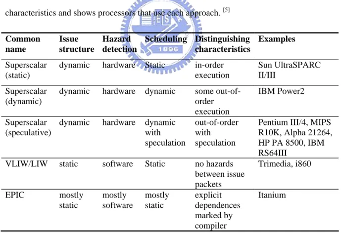
(17) hardware, since it knows, with no further checking, which operations it can start executing in the same cycle. The Explicitly Parallel Instruction Computing (EPIC) style of architecture is an evolution of VLIW that has also absorbed many superscalar concepts, albeit in a form adapted to EPIC. EPIC provides a philosophy of how to build ILP processors, along with a set of architectural features that support this philosophy. In this sense, EPIC is like RISC: The term denotes a class of architectures that subscribe to a common philosophy. Just as there is more than one distinct RISC instruction set architecture (ISA), there can also be more than one EPIC ISA. Depending on which EPIC features it uses, an EPIC ISA can be optimized for distinct domains such as general-purpose or embedded computing. Table 2.1 summarizes the basic approaches to multiple issue and their distinguishing characteristics and shows processors that use each approach. [5] Common name. Issue Hazard Scheduling Distinguishing Examples structure detection characteristics. Superscalar (static). dynamic. hardware. Static. in-order execution. Sun UltraSPARC II/III. Superscalar (dynamic). dynamic. hardware. dynamic. IBM Power2. Superscalar dynamic (speculative). hardware. dynamic with speculation. some out-oforder execution out-of-order with speculation. VLIW/LIW. software. Static. static. Pentium III/4, MIPS R10K, Alpha 21264, HP PA 8500, IBM RS64III Trimedia, i860. no hazards between issue packets Itanium EPIC mostly mostly mostly explicit static software static dependences marked by compiler Table 2.1: The five primary approaches in use for multiple-issue processors and the primary characteristics that distinguish them.. -7-.
(18) Although early superscalar processors used static instruction scheduling, and embedded processors still do, most leading-edge desktops and servers now use superscalars with some degree of dynamic scheduling.. 2.2 Explicitly Parallel Instruction Computing (EPIC) EPIC defines a new style of architecture that could rival RISC in terms of impact. This philosophy seeks to simplify hardware while extracting even more instruction-level parallelism from programs than either VLIW or superscalar strategies. [6] One of goals for EPIC was to retain VLIW’s philosophy of statically constructing the POE, but to augment it with features—akin to those in a superscalar processor—that would permit it to better cope with dynamic factors, which traditionally limited VLIW-style parallelism. To accomplish these goals, the EPIC philosophy has the following key aspects. •. Designing the desired POE at compile time EPIC places the burden of designing the POE on the compiler. Whereas, in general, a processor’s architecture and implementation can obstruct the compiler in performing this task, EPIC processors provide features that assist the compiler in designing the POE. An EPIC processor’s runtime behavior must be predictable and controllable from the compiler’s viewpoint. Dynamic out-of-order execution can obfuscate the compiler’s understanding of how its decisions will affect the actual ROE constructed by the processor; the compiler has to second-guess the processor, which complicates its task. An “obedient” processor, which does exactly what the program instructs it to do, is preferable.. -8-.
(19) The essence of engineering a POE at compile time is to reorder the original sequential code to best take advantage of the application’s parallelism and make best use of the hardware resources to minimize the execution time. Without suitable architectural support, this reordering can violate program correctness. Thus, because EPIC places the burden of designing the POE on the compiler, it must also provide architectural features that support extensive code reordering at compile time. •. Permitting the compiler to play the statistics An EPIC compiler faces a major problem in constructing the POE: Certain types of information that necessarily affect the ROE can only be known at runtime. For example, a compiler cannot know for sure which way each conditional branch will go, and, when scheduling code across basic blocks in a control flow graph, the compiler cannot know for sure which control-flow path is taken. In addition, it is typically impossible to construct a static schedule that jointly optimizes all paths within the program. Ambiguity also results when a compiler is unable to resolve whether memory references are to the same location. If they are, they need to be sequentialized. If not, they can be scheduled in any order. With such ambiguities, there often exists a strong probability of a particular outcome. An important part of the EPIC philosophy is to allow the compiler to play the odds under such circumstances—the compiler constructs and optimizes a POE for the likely case. However, EPIC provides architectural support—such as control and data speculation, which we discuss later—to ensure program correctness even when the guess is incorrect. When the gamble does not pay off, program execution can incur a performance penalty. The penalty is sometimes visible within the program schedule, for instance. -9-.
(20) when a branch exits a highly optimized program region and then executes code within a less optimized region. Or, the penalty may be incurred in stall cycles that are not visible in the program schedule; certain operations execute at full performance for the likely, optimized case but stall the processor to ensure correctness for the less likely, non-optimized case. •. Communicating the POE to the hardware Having designed a POE, the compiler must communicate it to the hardware. To do so, the ISA must be rich enough to express the compiler’s decisions as to when to issue each operation and which resources to use. In particular, it should be possible to specify which operations are to issue simultaneously. The alternative would be for the compiler to create a sequential program that the processor reorganizes dynamically to yield the desired ROE. But this defeats EPIC’s goal of relieving the hardware of the burden of dynamic scheduling. When communicating the POE to the hardware, it is important to provide critical information at the appropriate time. A case in point is a branch operation, which—if it is going to be taken—requires that instructions start being fetched from the branch target well in advance of the branch being issued. Rather than providing hardware to deduce when to do so and what the target address is, the EPIC philosophy provides this information to the hardware, explicitly and at the correct time, via the code. There are other decisions the microarchitecture makes that are not directly concerned with code execution, but which do affect execution time. One example is cache hierarchy management and the associated decisions as to what data to promote up the hierarchy and what data to replace. Such policies are typically built into the. - 10 -.
(21) cache hardware. EPIC extends its philosophy of having the compiler orchestrate the ROE to having it also manage these microarchitectural mechanisms. To this end, EPIC provides architectural features that permit programmatic control of mechanisms that the microarchitecture normally controls.. 2.3 Dynamic Execution The potential performance gains of a dynamic execution engine are facilitated by the following two techniques: •. Dynamic scheduling: Instructions are reordered to reduce unnecessary stalls.. •. Register renaming: Registers are renamed to eliminate false dependencies. Typically, the dynamic portion of the processor consists of a register renaming. mechanism, which maps between temporary and architectural files, a reorder buffer, reservation stations, and execution units.. 2.3.1 Dynamic Scheduling A simple statically scheduled pipeline fetches an instruction and issues it, unless there was a data dependence between an instruction already in the pipeline and the fetched instruction that cannot be hidden with bypassing or forwarding. (Forwarding logic reduces the effective pipeline latency so that the certain dependences do not result in hazards.) If there is a data dependence that cannot be hidden, then the hazard detection hardware stalls the pipeline (starting with the instruction that uses the result). No new instructions are fetched or issued until the dependence is cleared. [5] We explore an important technique, called dynamic scheduling, in which the hardware rearranges the instruction execution to reduce the stalls while maintaining data flow and exception behavior. Dynamic scheduling offers several advantages: It enables handling some - 11 -.
(22) cases when dependences are unknown at compile time (e.g., because they may involve a memory reference), and it simplifies the compiler. Perhaps most importantly, it also allows code that was compiled with one pipeline in mind to run efficiently on a different pipeline. As we will see, the advantages of dynamic scheduling are gained at a cost of a significant increase in hardware complexity. Although a dynamically scheduled processor cannot change the data flow, it tries to avoid stalling when dependences, which could generate hazards, are present. In contrast, static pipeline scheduling by the compiler (covered in the next chapter) tries to minimize stalls by separating dependent instructions so that they will not lead to hazards, Of course, compiler pipeline scheduling can also be used on code destined to run on a processor with a dynamically scheduled pipeline. A major limitation of the simple pipelining techniques is that they all use in-order instruction issue and execution: Instructions are issued in program order, and if an instruction is stalled in the pipeline, no later instructions can proceed. Thus, if there is a dependence between two closely spaced instructions in the pipeline, this will lead to a hazard and a stall will result. If there are multiple functional units, these units could lie idle. If instruction j depends on a long-running instruction i, currently in execution in the pipeline, then all instructions after j must be stalled until i is finished and j can execute. For example, consider this code: mul add sub. fO, f2, f4 f1O, fO, f8 f12, f8, f14. The sub instruction cannot execute because the dependence of add on mul causes the pipeline to stall; yet sub is not data dependent on anything in the pipeline. This hazard creates a performance limitation that can be eliminated by not requiring instructions to execute in program order.. - 12 -.
(23) To allow us to begin executing the sub in the above example, we must separate the issue process into two parts: checking for any structural hazards and waiting for the absence of a data hazard. We can still check for structural hazards when we issue the instruction; thus, we still use in-order instruction issue (i.e., instructions issued in program order), but we want an instruction to begin execution as soon as its data operand is available. Thus, this pipeline does out-of-order execution, which implies out-of-order completion.. 2.3.2 Register Renaming Issue on Predicated Code As the instructions enter the renaming stage in processor, all registers are renamed and each register definition is assigned a unique physical register. Occasionally, the renaming mechanism may need to stall the pipeline if some predicates are not fully resolved. This situation occurs when the renaming unit processes multiple instructions that, guarded by different unresolved predicates, write to a common architectural register. As usual, each definition of this common register would be assigned a unique physical register during renaming. When a consumer instruction that uses the common register reaches the rename stage, the renaming would become ambiguous. Without evaluating the predicates that guarded the definitions of the common register, the renaming unit cannot yet map the common register to the correct physical register. Thus, the processor needs stall the consumer instruction until the predicates are resolved. The stall would induce bubbles in the pipeline and may result in performance loss. [7]. - 13 -.
(24) Before Rename I5: I6: I7:. (p8) mov (p9) ld cmp. r14 = r21 r44 = [r50] p6, p7 = r44, 0. After Rename I5: I6: I7:. (pQ) mov (pR) ld cmp. rA = rE rB = [rF] pS, pT = r(A? or B?), 0. Figure 2.1: Renaming issue In our example above, both the mov instruction I5 and the ld instruction I6 assign their results to the same architectural register r44, and they are guarded by p8 and p9, respectively. Figure 2.1 shows the instructions before and after renaming. To distinguish from the architectural registers, we use alphabetical letters to identify the physical registers. After renaming, the definitions of r44 by I5 and I6 are assigned to rA and rB, respectively. With unresolved predicates, the renaming of r44, the source operand of the consumer instruction I7, cannot yet be determined for using either rA or rB. Thus, until the predicates are resolved,. the processor needs to stall I7 to prevent it from entering the rename stage.. 2.4 Related Work In order to hide the stall latencies, some software approaches and hardware approaches were purposed. In the following subsections, we introduce two approaches. One is called “advanced load”, implemented in real Itanium processors. The other is a survey of the speedups gained by out-of-order execution Itanium processor over the baseline in-order processor. However, it is too complex to implement on hardware.. - 14 -.
(25) 2.4.1 Advanced Load Data speculation is the execution of a memory load prior to a store that preceded it and that may potentially alias with it. Data speculative loads are also referred to as “advanced loads”. [1] Consider the code sequence below: store(st_addr, data) load(ld_addr, target) use(target). The process of determining at compile time the relationship between memory addresses is called disambiguation. In the example above, if ld_addr and st_addr cannot be disambiguated, and if the load were to be performed prior to the store, then the load would be data speculative with respect to the store. If memory addresses overlap during execution, a data-speculative load issued before the store might return a different value than a regular load issued after the store. Therefore analogous to control speculation, when the compiler data speculates a load, it leaves a check instruction at the original location of the load. The check verifies whether an overlap has occurred and if so it branches to recovery code. The code sequence above now translates into: /* off critical path */ aload(ld_addr, target) /* other operations including uses of target */ store(st_addr, data) acheck(target, recovery_addr) use(target). Due to explicit support to control speculation and data speculation provided in the Itanium architecture, the advanced compiler can potentially achieve performance comparable to out-of-order execution through effective instruction scheduling. However, in applications with complex memory access patterns and very short load-to-use distances, it is difficult for the compiler to reduce the impact of cache misses for such applications.. - 15 -.
(26) 2.4.2 Out-of-order Execution Itanium Processor As the speeds of processors and memory systems continue to diverge, the performance of a processor depends more heavily on its ability to hide memory latency. In-order execution processors, such as the current Itanium processor designs, may suffer an expensive stall when servicing data cache misses. This problem is exacerbated in programs exhibiting hard-topredict memory accesses. To effectively hide the latency for in-order execution processors, microarchitecture enhancements as well as software optimizations can be applied. For example, caches can be implemented as non-blocking caches to avoid unnecessary processor stalls, or the compiler can insert prefetch hints into the program. This related work evaluates the memory latency tolerance microarchitecture approaches for the future Itanium processors. The approach is to implement an out-of-order execution core. [8] Out-of-order (OOO) execution allows the processor to dynamically schedule the code and adapt to the run-time behavior of the program. Its major objectives are to prevent unnecessary stalls and to hide memory latency. Due to explicit support to control speculation and data speculation provided in the Itanium architecture, the advanced compiler can potentially achieve performance comparable to out-of-order execution through effective instruction scheduling. However, in applications with complex memory access patterns and very short load-to-use distances, it is difficult for the compiler to reduce the impact of cache misses for such applications. An out-of-order Itanium core can discover independent instructions dynamically and overlap their execution with the unpredictable outstanding cache misses, thereby effectively hiding the miss latency. This related work compares the speedups gained by the OOO processor over the baseline in-order processor. The in-order baseline processor suffers significant performance losses due to the large number of cache misses incurred in the memory-intensive benchmarks. The in-order pipeline stalls when an instruction attempts to use the destination register of an - 16 -.
(27) outstanding load miss. The memory-intensive benchmarks often have extensive use of pointer de-references, which are translated into adjacent dependent loads with very short distances in between. Consequently, cache misses on the dependent loads will quickly induce pipeline stalls upon these nearly immediate uses. The OOO processor can achieve an impressive speedup over the baseline in-order processor, with 87% average across the memory-intensive benchmarks. For the compute-intensive benchmarks, OOO can achieve on average 27% speedup over in-order due to OOO’s ability to tolerate L1 cache misses.. - 17 -.
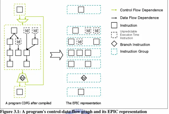
(28) Chapter 3 Design of Out-of-order Execution Mechanism In this chapter, we propose an out-of-order execution mechanism on EPIC architecture to handle stalls. Then we describe the design detail of the hardware and software additions.. 3.1 Concept When a program compiled, the program should become a control-data-flow graph (CDFG). The graph contains all the program information, including basic blocks, instructions, control flow dependences, and data flow dependences. In order to keep the execution order, compiler should have some way to show the processor when to execute which instructions. As Figure 3.1, the EPIC architecture uses instruction groups to keep the information of control flow dependences and data flow dependences. Comparing to VLIW, the instruction group is an easy way not only to keep dependences information, but also flexible.. - 18 -.
(29) Figure 3.1: A program's control-data-flow graph and its EPIC representation. Figure 3.2: One instruction stall occurred, whole instruction group stall.. - 19 -.
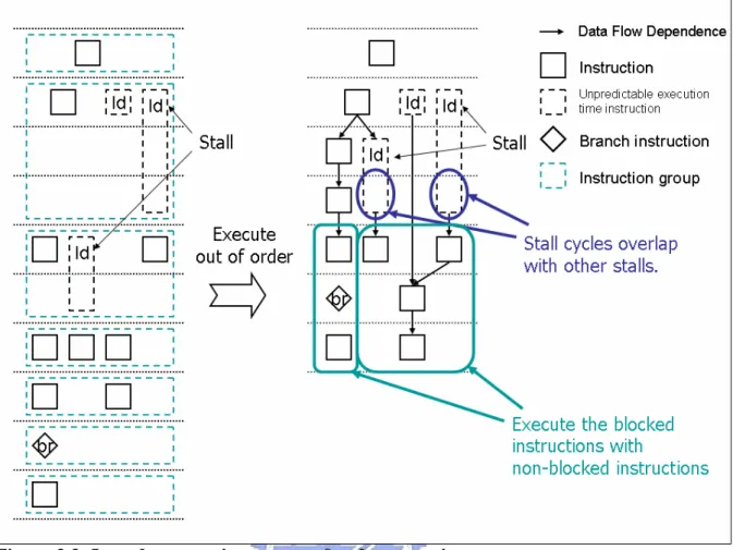
(30) 3.1.1 The Stall Problem of Instruction Groups Once instructions are issued as a group, they will proceed as a group through the pipeline. If one instruction in the issue group has a stall condition, the whole group will stall. This stall will also stall all instructions behind it (younger). Figure 3.2 shows the execution result if the second instruction group has 2 cycles stall and the third instruction group has 1 cycle stall. In fact, when the stall occurred, some instructions can still be executed if there is no data dependence from the stalled instruction. The way to solve this problem is using an out-of-order execution mechanism. Through the instruction group is an easy way to keep dependences information, it loses the detail dependence information about each instruction in the group. Even if the function unit is not busy, no information can guarantee which instruction can be executed without waiting the execution of previous instruction group completed.. 3.1.2 Observation When an instruction group is executed completely, all the result defined by those instructions will be ready, and the instruction of next instruction group can use the result without hazard detecting. It means that all instructions in the true dependency chain will appear continuously in each instruction groups. As Figure 3.3, if we allow instructions to execute out of order when there are sufficient resources and no data dependences, only overlapping the stall cycles can gain the benefit. In other words, even if all non-blocked instructions are executed, the blocked instructions need to be executed later and no other instruction can overlap with, and no clock cycle saved.. - 20 -.
(31) Figure 3.3: In-order execution vs. out-of-order execution In the superscalar architecture, the performance gains of a traditional dynamic execution mechanism are facilitated by dynamic scheduling and register renaming. However, a register renaming mechanism is not suitable on a predicated code and the mechanism needs to speculate the register name with instructions executed before. We do not use register renaming mechanism in this design. In order to execute out of order without checking the dependence relation, we introduce a hint attached on each instruction to control the dependency and add some hardware modification.. - 21 -.
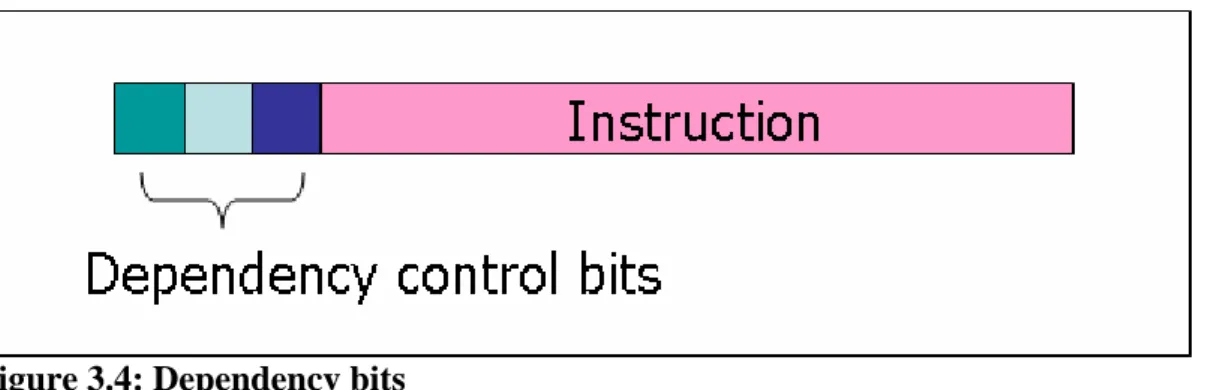
(32) 3.2 Dependency Control Because we allow some blocked instructions to be executed later, the non-blocked instructions cannot use the registers used by those blocked instructions. We introduce the dependency control to keep the dependency relations, like the scoreboard mechanism, the dependency control knows which instructions shall be blocked when an instruction stalled, and preserves the execution correctness without checking them in execution stage. The dependency control is divided into two parts: the dependency bit and the hardware modification.. 3.2.1 Dependency Bit Without a complex hardware circuit checking dependences, a dependency bit represents all registers needed by a stall instruction and instructions depending on it. All instructions dependent on a stall instruction can overlap with other instructions independent from the stall dependency chain. We use one bit only to record the first continuous instructions in whole dependency chain and preserve all registers used by those continuous instructions. One bit gives one opportunity of out-of-order execution.. Figure 3.4: Dependency bits For each instruction, we attach some dependency bits on it. Figure 3.4 shows the instruction format after attaching dependency bits. Those bits are disjoint and can be used in the same instruction.. - 22 -.
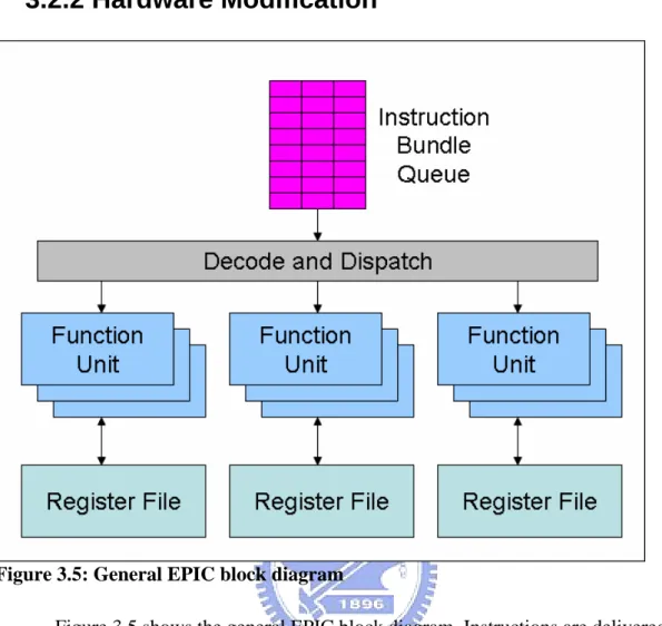
(33) 3.2.2 Hardware Modification. Figure 3.5: General EPIC block diagram Figure 3.5 shows the general EPIC block diagram. Instructions are delivered to the processor in bundles, and the instruction bundles will be issued into the instruction bundle queue. The instructions in queue deliver and execute in groups. Instructions in different group will not be deliver at the same time.. - 23 -.
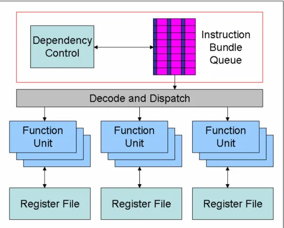
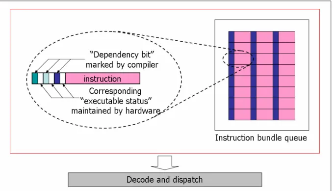
(34) Figure 3.6: Proposed EPIC architecture with dependency control block Figure 3.6 is the proposed EPIC architecture. We modify the instruction bundle queue, and add a dependency control block. Detail of the dependency control block is in Figure 3.7. Each instruction has its own depency bits and the executable status corresponding to each bit.. - 24 -.
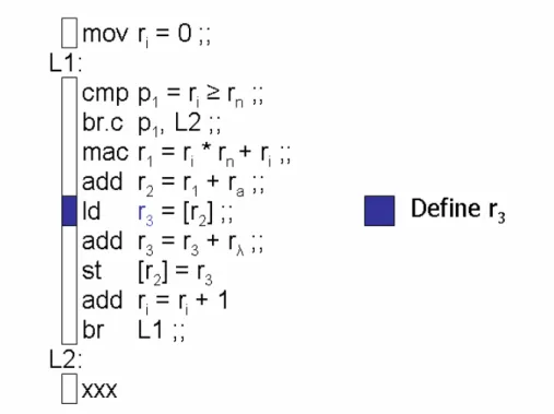
(35) Figure 3.7: Detail of the dependency control The dependency control block follows the execution policy listed below: •. For each dependency bit, executes instructions in the instruction group order.. •. Before executing marked instructions, sets the executable status to all continuous instructions when no instruction with the same bit is executing.. •. An instruction group cannot be executed if one corresponding executable status of any instruction in the group is not set.. •. No more instruction can be executed when a control instruction (branch, call, or return) is blocked.. 3.3 Dependency Bit Marking Method The dependency bit is marked in compile time. We divide the dependency bit marking method into four steps. We also give an example to see how it works. 1. Mark all instructions which may cause stall.. - 25 -.
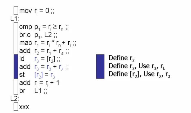
(36) At this step, we assume that there are infinity dependency bits, find out all possibly stall instructions, and give each possibly stall instruction a control bit. If two or more stall instructions appear in the same instruction group, we may share the same dependency bit with those stall instructions. Note that at this step, the dependency bit only represents the destination register of that instruction, because when this stall happened, destination register may not be defined, and can not to be used by nonblocked instruction. For example, to mark the instruction “ld r3 = [r2]”, only register r3 need to be concerned.. Figure 3.8: Step 1: Mark all instructions which may cause stall. 2. Mark all continuous instructions needed to be blocked when that stall occurred. All continuous instructions within the data dependency chain must be marked. In order words, all instructions which have data dependences (RAW, read after write) or name dependences (WAR, write after read, and WAW, write after write) to the destination register of the previous step must be marked.. - 26 -.
(37) When the length of continuous dependency chain is longer than the instruction queue length, we just simply discard up the mark. Because when the stall occur, the non-blocked instructions cannot issue into the instruction queue, and no more instruction can be executed until the stall instruction finished. When the dependency chain is not continuous, we stop tracing and go to next step.. Figure 3.9: Step 2: Mark all continuous instructions needed to be blocked when that stall occurred. 3. Mark the first instruction which has dependency relation to those blocked instructions. We don’t use the register renaming mechanism in this design. In order to execute program correctly, no more than the first instruction with data dependence the continuous dependency chain can be executed. So we mark the first non-continued instruction with register conflict (data dependences or name dependences).. - 27 -.
(38) If a control instruction is met, stop tracing at that instruction and mark it when the branch target is unknown (indirect branch, call library, or return), or just tracing all possible paths otherwise. Figure 3.10 shows that the control instruction “br L1” meet, we continue to trace code after L1, because they are in the same procedure. The instruction “add r2 = r1 + ra” need to be marked because it write r2 after the store instruction “st [r2] = r3” read. Note that instructions after L2 need to be checked, because the. branch instruction “br.c p1, L2” is conditional.. Figure 3.10: Step 3: Mark the first instruction with data dependence after the continuous dependency chain.. - 28 -.
(39) 4. Discard or merge marks. If the resisters used by one dependency bit are subset of another dependency bit in the same code fragment, we discard the subset one of the marks. As Figure 3.11, the dependency bit is redundant.. Figure 3.11: Discard the redundant dependency bit. Also, if we run out of dependency bit, we shall discard or merge them to fit the limitation. Figure 3.12 shows the merging case of no overlap situation. Two dependency bits are merged to one. Figure 3.13 shows another case, if we want to merge dependency bits with some overlap instruction groups, we should take care of all possible stalls and prevent all possible incorrectness.. - 29 -.
(40) Figure 3.12: Merge two dependency bit without overlap.. Figure 3.13: Merge two dependency bit with overlap.. - 30 -.
(41) 3.4 Example We will show the execution process of one dependency control bit machine in Figure 3.14 to Figure 3.30 below.. Figure 3.14: The 1st clock cycle. There are 3 function units and 8 slot of instruction bundle queue.. - 31 -.
(42) Figure 3.15: The 2nd clock cycle.. Figure 3.16: The 3rd clock cycle.. - 32 -.
(43) Figure 3.17: The 4th clock cycle.. Figure 3.18: The 5th clock cycle.. - 33 -.
(44) Figure 3.19: The 6th clock cycle. A marked instruction can be executed if no stall instructions with the same mark in the function units. When execute a marked instruction, the executable status of all continuous instructions are set.. Figure 3.20: The 7th clock cycle. A stall occurred.. - 34 -.
(45) Figure 3.21: The 8th clock cycle. The blocked instructions are skipped at this time. Note that these two instructions can be executed at the same time because they belong to the same instruction group. A branch mispredict occurred at this clock cycle.. Figure 3.22: The 9th clock cycle.. - 35 -.
(46) Figure 3.23: The 10th clock cycle.. Figure 3.24: The 11th clock cycle.. - 36 -.
(47) Figure 3.25: The 12th clock cycle.. Figure 3.26: The 13th clock cycle. No instruction can be executed until the stall instruction completed.. - 37 -.
(48) Figure 3.27: The 14th clock cycle. The stall instruction is completed. Blocked instructions in the queue can be executed now.. Figure 3.28: The 15th clock cycle.. - 38 -.
(49) Figure 3.29: The 16th clock cycle. Set the executable status of next continuous marked instructions.. Figure 3.30: The 17th clock cycle.. - 39 -.
(50) Chapter 4 Simulation Environment and Result In this chapter, we will describe the simulation environment, including simulator, compiler, and benchmarks. Then we will show the simulation results of total execution time and give an analysis for the simulation results.. 4.1 Simulation Environment The only one implementation of EPIC architecture is the Intel IA-64 Itanium family. We use the Itanium 2 processor for the simulation target processor.. 4.1.1 IA-64 Simulator The IA-64 is a RISC-style, register-register instruction set, but with many novel features designed to support compiler-based exploitation of ILP. The components of the IA-64 register state are •. 128 64-bit general-purpose registers, which as we will see shortly are actually 65 bits wide. •. 128 82-bit floating-point registers, which provide two extra exponent bits over the standard 80-bit IEEE format. •. 64 1-bit predicate registers - 40 -.
(51) •. 8 64-bit branch registers, which are used for indirect branches. •. a variety of registers used for system control, memory mapping, performance counters, and communication with the OS. Execution unit slot I-unit. Instruction type A I. Instruction description Integer ALU Non-ALU integer. Example instructions. add, subtract, and, or, compare integer and multimedia shifts, bit tests, moves M-unit A Integer ALU add, subtract, and, or, compare M Memory access Loads and stores for integer/FP registers F-unit F Floating point Floating-point instructions B-unit B Branches Conditional branches, calls, loop branches L+X Extended Extended immediates, stops and no-ops L+X Table 4.1: The five execution unit slots in the IA-64 architecture and what instructions type they may hold are shown. The IA-64 instruction set architecture (ISA) includes six instructions types, which are A-type, I-type, M-type, F-type, B-type, and L+X-type. A-type instructions, which correspond to integer ALU instructions, may be placed in either an I-unit or M-unit slot. L+X slots are special, as they occupy two instruction slots; L+X instructions are used to encode 64-bit immediates and a few special instructions. L+X instructions are executed either by the I-unit or the B-unit. There is no open source IA-64 simulator. We write a simulator to simulate the processor. Our simulator simulates all the A-type instructions, I-type instructions, M-type instructions, and B-type instructions. This simulator also simulates some F-type instructions. The simulator counts the clock cycles and simulate the branch mispredict, instruction fetch stalls, and data access cycles.. - 41 -.
(52) 4.1.2 IA-64 Compiler We use two of the free C/C++ compiler for IA-64 architecture as below: •. Microsoft C/C++ Optimizing Compiler for IA-64. •. GNU C/C++ compiler These two compilers can save the object file into ELF64 format for our simulator.. Instead of code rewriting, we write an independent program to provide the dependency bits and store the result in the corresponding file.. 4.1.3 Benchmarks Because some of the floating-point instructions not implemented, we only write two simple benchmarks. One is computer-intensive program, which is a RSA algorithm implementation. The other is memory-intensive program, which is just implementing a block memory coping.. 4.2 Simulation Results and Analysis The length of continuous instructions after each stall instruction is very short in our chosen compilers. Figure 4.1 is the counting result of a parser generator called ‘Bison’. So we just simply use infinity dependency bits without concerning the overhead of merging them.. - 42 -.
(53) Figure 4.1: The length of continuous instructions after each stall instruction.. Figure 4.2: Simulation Results. - 43 -.
(54) Figure 4.2 shows the simulation results. For compute-intensive program, 24.2% of total clock cycles will be saved. For memory-intensive program, 48.1% of total clock cycles can be saved. The simulation results show us that when executing a compute-intensive program, stall can overlap with other non-stall instructions and execute the blocked instructions later with non-stall instructions. When a memory intensive program executed, stall cycles can overlap with other stall cycles. The real performance gain may less than the result because some other stalls are not simulated. However, those stalls can still be overlapped.. - 44 -.
(55) Chapter 5 Conclusions and Future Works This chapter concludes this thesis. We summarize and conclude this study in section 5.1. Section 5.2 points out some possible issues worth further investigation.. 5.1 Conclusions In this thesis, an approach to an out-of-order execution EPIC is proposed and simulated. Complier gives the hint of handling stall cycles to hardware instead of using a complex circuit to detect the instruction dependency. In order to hide the stall cycles and become an out-of-order execution processor, the way to keep the dependency relation is the key point of this research. Not only retain the dependency information between each instruction, but also execute them correctly. The dependency chain will occupy whole execution resources very soon, and no more instruction can be executed if stall duration is too long. Therefore, the out-of-order execution mechanism is most effective in tolerating stall penalty of short instruction length. As the simulation results, both compute-intensive program and memory-intensive program can get the performance improvement.. - 45 -.
(56) 5.2 Future Works Still, there are some other issues worth further investigation. This design is a conservative approach to prevent the incorrect execution. It is not an optimized out-of-order execution mechanism. To become an optimized approach, maybe all the dependency relations are needed and it may hard to store those relations. The simulator of this thesis assumes that there are infinity dependency bits without concerning the merging issue. This issue may need to be verified and improve the merging method. Finally, comparing to the simultaneous multi-threading technology (SMT) where multiple threads of software applications can be run simultaneously on one processor, it is effective in tolerating large stall penalty. They don’t have conflict and the combination of these technologies may be interesting.. - 46 -.
(57) References [1]. Intel Itanium Architecture Software Developer’s Manual Volume 1: Application Architecture, Revision 2.1. [2]. Intel Itanium Architecture Software Developer’s Manual Volume 2. System Architecture, Revision 2.1. [3]. Intel Itanium Architecture Software Developer’s Manual Volume 3. Instruction Set Reference, Revision 2.1. [4]. Intel Itanium 2 Processor Reference Manual For Software Development and Optimization. [5]. Computer Architecture: A Quantitative Approach, Third Edition John L. Hennessy; David A. Patterson. [6]. EPIC: Explicitly Parallel Instruction Computing Schlansker, M.S.; Rau, B.R. Computer, Volume: 33, Issue: 2, Feb. 2000. [7]. Register renaming and scheduling for dynamic execution of predicated code Wang, P.H.; Hong Wang; Kling, R.M.; Ramakrishnan, K.; Shen, J.P. High-Performance Computer Architecture, 2001. HPCA. The Seventh International Symposium on, 19-24 Jan. 2001. [8]. Memory Latency-Tolerance Approaches for Itanium Processors: Out-of-Order Execution vs. Speculative Precomputation Wang, P.H.; Hong Wang; Collins, J.D.; Grochowski, E.; Kling, R.M.; Shen, J.P. High-Performance Computer Architecture, 2002. Proceedings. Eighth International Symposium on, 2-6 Feb. 2002. - 47 -.
(58)
數據
+7
相關文件
circuit sat: Given a circuit, is there a truth assignment such that the circuit outputs truea. • circuit sat ∈ NP: Guess a truth assignment and then evaluate
Machine language ( = instruction set) can be viewed as a programmer- oriented abstraction of the hardware platform. The hardware platform can be viewed as a physical means
Machine language ( = instruction set) can be viewed as a programmer- oriented abstraction of the hardware platform. The hardware platform can be viewed as a physical means
Instead, we could move the point P to the outside of the triangle, the parallelograms and the regular polygons and generalize the original result to be the form of the fixed sum of
A factorization method for reconstructing an impenetrable obstacle in a homogeneous medium (Helmholtz equation) using the spectral data of the far-field operator was developed
A factorization method for reconstructing an impenetrable obstacle in a homogeneous medium (Helmholtz equation) using the spectral data of the far- eld operator was developed
We would like to point out that unlike the pure potential case considered in [RW19], here, in order to guarantee the bulk decay of ˜u, we also need the boundary decay of ∇u due to
According to the historical view, even though the structure of the idea of Hua-Yen Buddhism is very complicated, indeed, we still believe that we can also find out the
