Cite this: RSC Advances, 2013, 3, 559
Formation of size-tunable dandelion-like hierarchical
rutile titania nanospheres for dye-sensitized solar cells3
Received 7th November 2012, Accepted 7th November 2012 DOI: 10.1039/c2ra22807f www.rsc.org/advances
Chi-Ming Lan, Shang-En Liu, Jia-Wei Shiu, Jyun-Yu Hu, Meng-Hung Lin and Eric Wei-Guang Diau*
A sol–gel method with a modified solvent comprising of three simple steps under low-temperature
conditions was used to synthesize mono-disperse rutile TiO2nanospheres with dandelion-like hierarchical
morphology (DHRS) as a light-scattering layer for dye-sensitized solar cells (DSSC). 1,2-Ethanediol (ED)
served as a key retardation agent in the second step at 25uC to slow the hydrolysis and condensation of
the TiCl4aqueous solution prepared in the first step at 0uC; the subsequent nucleation of a rutile type
phase occurred homogeneously in the third step at 70uC to generate the rutile TiO2nanospheres with
highly uniform sizes. The spherical sizes of DHRS were well controlled with the volume ratios of the ED-water solvent mixture in the second step, for which the DHRS of diameter 650–200 nm were produced from the solvent system containing 5–25% ED. A detailed mechanism is presented to rationalize the formation of nanospheres of uniform size in six steps: 1) hydration and hydrolysis, 2) hydrolysis and retardation, 3) hydrolysis and condensation, 4) homogeneous nucleation, 5) aggregation and growth of rod-like crystals and 6) DHRS formation. The DSSC device with a scattering layer made of DHRS (size ~300
nm) performed comparably to that with a scattering layer made of a commercially available TiO2paste,
making this nano-material a cost-effective alternative for future DSSC commercialization.
Introduction
Dye-sensitized solar cells (DSSC) have attracted much atten-tion because they present a highly promising alternative to conventional photovoltaic devices with the advantages of light weight, low cost, and ease of processing.1–4 Efficiencies of conversion of light to electric power (g) greater than 11% have been obtained with polypyridyl ruthenium complexes5–8 and zinc porphyrin sensitizers9–12 adsorbed on nanoporous TiO2
films. For most of the highly efficient Ru-based photosensi-tizers,5–8 the absorption in the 600–800 nm region is weak
because of the forbidden nature of the singlet–triplet excita-tion of the Ru dyes. To enhance the light-harvesting ability of the dye, many strategies have been applied.13 For example, well-ordered one-dimensional TiO2 nanotube (TNT) arrays
served as working electrodes with a native light-scattering effect;14–16 flower-like platinum nanostructures served as counter electrodes with a highly reflective character;17 and
micro-spherical porous TiO2voids served as scattering centers
for DSSC.18,19A traditional approach to enhance the efficiency of light harvesting is to prepare the TiO2films with a
double-layer structure, for which a light-scattering double-layer (LSL) with particles of size 250–300 nm was added on top of a transparent TiO2 active layer containing nanoparticles ~20 nm.13,20–22
Moreover, multiple TiO2layers containing small (~20 nm) and
large nanoparticles (~100 nm) at various mixing ratios served as working electrodes for DSSC to achieve a performance significantly enhanced relative to a device made of solely its TiO2monolayer counterpart.23
Although the TiO2LSL has an advantage of improving the
light harvesting ability of the dye, the large particle size with modest surface area would decrease the amounts of dye loaded on TiO2films. To combine both dye-loading ability and
light-scattering effect in one TiO2 layer, Lee and Park
developed mesoporous TiO2hollow spheres with spherical size
1–3 mm and wall thickness ~250 nm;24 Caruso and Cheng
developed mesoporous spherical TiO2beads of size 830 nm.25–27
Both hollow spheres and beads are composed of TiO2
nanopar-ticles in the anatase phase of size ~20 nm so that they exhibited an excellent bi-functional character for use as photoanodes to promote the overall performance of the DSSC. Anatase hierarch-ical TiO2spheres consisting of various nanostructures, such as
nanorods,28 nanocubes29 and nanosheets,30 were reported for
DSSC applications. These investigations29–31 indicate that the device performance depends on the fraction of exposed {001} facets in the anatase TiO2 single crystals – the greater the
fraction, the better the performance.31
Department of Applied Chemistry and Institute of Molecular Science, National Chiao Tung University, Hsinchu 30010, Taiwan E-mail: [email protected]; Fax: +886-3-5723764; Tel: +886-3-5131524
3Electronic supplementary information (ESI) available: Supplementary figures, Fig. S1–S4, and supplementary tables, Tables S1–S2. See DOI: 10.1039/
PAPER
Published on 08 November 2012. Downloaded by National Chiao Tung University on 28/04/2014 02:15:45.
View Article Online
Size-tunable mono-dispersed mesoporous TiO2 spheres
were produced via controlled sol–gel processes and subse-quent solvothermal treatment using various titania precur-sors.32–35 For example, the rates of hydrolysis of titanium tetraisopropoxide (TTIP) in water were controlled on varying the molar ratios of TTIP to H2O (r-factor) so that the size of
nanoporous TiO2spheres can be set over a range 260–980 nm
because the nucleation and growth of the titania colloids were well separated in two steps.33When these TiO2submicrometer
spheres were used as LSL in a double-layer structure for DSSC, the devices showed the best light-scattering performance with particle size ~500 nm.33–35Although TiO2spheres of uniform
size at varied diameters were satisfactorily produced, the crystallization of TiO2in the anatase phase requires a tedious
hydrothermal (or solvothermal) treatment, which is costly and unnecessary if those mono-disperse TiO2spheres serve as LSL
for DSSC. Our present work has developed a simple non-hydrothermal synthetic approach to prepare the TiO2 of
uniform size featuring dandelion-like hierarchical rutile spheres (DHRS) with retarded hydrolysis and condensation of the TiCl4precursor in the presence of 1,2-ethanediol (ED),
for which the size of these DHRS is well controlled in a range 200–650 nm on adjusting the volume ratios of ED and H2O to
allow homogeneous nucleation under conditions of low temperature, T = 70 uC. The DSSC device fabricated using the DHRS of size ~300 nm achieved g = 9.3% (dye = Z907), which is comparable with, or superior to, that of a device made of expensive commercial LSL TiO2pastes with nanoparticles of
mixed size or with a broad distribution of size under the same experimental conditions.
Experiments
Preparation of TiO2DHRS
Mono-disperse TiO2 DHRS with spherical size in the range
200–650 nm were prepared according to a simple hydrolysis/ condensation at a low temperature. First, liquid titanium tetrachloride (5 mL, 99% TiCl4, Aldrich) was slowly added into
a beaker containing ice water (50 mL, 0uC) and stirred for 1 h; the color of the TiCl4 aqueous solution turned from initially
milky to transparent after stirring. Second, the transparent solution in the original beaker was added to another beaker containing solvent mixture (50 mL, 25uC) and stirred for 1 h to complete the two-step hydrolysis. Third, depending on the volume ratios of the solvent mixture, the pre-treated transpar-ent solution was heated at 70uC for 2 h (0.5–1 h in the case of pure water) to complete the condensation and nucleation to form DHRS. These spheres were then collected on centrifuga-tion, washed several times with ethanol, and dried at 100uC. To prepare a screen-printable paste, ethyl cellulose, ethanoic acid and a-terpineol were added to the ethanol solution of the TiO2DHRS; ethanol was then removed from the solution with
a rotary evaporator to obtain a viscous paste suitable for screen printing.36
The solvents employed in the second hydrolysis process include ethanol (CH3CH2OH), 1,2-ethanediol (ethylene glycol,
HOCH2CH2OH), 1,3-propanediol (trimethylene glycol,
HO(CH2)3OH), 1,4-butanediol (tertamethylene glycol,
HO(CH2)4OH) and 1,5-pentanediol (pentamethylene glycol,
HO(CH2)5OH). For an appropriate control of the size of the
DHRS, the volume ratios of ED/water (total volume 100 mL) were varied: 0/100 (pure water; ED0), 5/95 (ED5), 10/90 (ED10), 15/85 (ED15), 20/80 (ED20) and 25/75 (ED25). TiO2 DHRS of
controlled size were thus synthesized from hydrolysis and condensation of TiCl4(5 mL) in solvent mixtures (100 mL in
total) with the ED/H2O volume ratio varied from 5% to 25%;
the diameters of the TiO2DHRS were thereby controlled to be
650, 550, 400, 300 and 200 nm for solvent systems ED5, ED10, ED15, ED20 and ED25, respectively.
Spectral and structural characterizations
The reflectance spectra of the TiO2films were measured with a
UV-visible-NIR spectrophotometer (V-570, JASCO) equipped with an integrating sphere (ISN-470, JASCO). The morpholo-gies of the TiO2 samples were investigated with a
field-emission scanning electron microscope (FESEM, JSM-7401F, JEOL). The microstructures of the products were further analyzed with a high-resolution transmission electron micro-scope (FE-HRTEM, JEM-2100F, JEOL) with energy-dispersive X-ray (EDX) analysis of the composition. The crystal phases of the products were characterized with an X-ray diffractometer (XRD, X9Pert Pro, PANalytical, Cu-Ka radiation), in a range 2q from 10 to 80 degree.
Fabrication of DSSC
For the working electrode, a paste composed of TiO2 NP
(particle size ~20 nm) prepared with a combined sol–gel/ hydrothermal method37,38 as a transparent active layer was coated on a TiCl4-treated FTO glass substrate (TEC 7, Hartford,
USA) to obtain the required thickness (~14 mm) of a film with repetitive screen printing. Apart from our DHRS, three commercially available TiO2 scattering pastes, PST-400C
(CCIC, JGC Catalysts and Chemicals Ltd, Japan), 18NR-AO (Dyesol Ltd, Australia) and R/SP (Solaronix SA, Switzerland) served as LSL to print on top of the transparent nanocrystal-line TiO2 active layer. The TiO2 films with a double-layer
structure were annealed according to a programmed proce-dure: heating at 80uC for 15 min, at 135 uC for 10 min, at 325 uC for 30 min, at 375 uC for 5 min, at 450 uC for 15 min, and at 500uC for 15 min. The TiO2films (active size 0.4 6 0.4 cm2) as
prepared were sensitized in a solution (Z907 dye, Solaronix, 3
6 1024 M) containing chenodeoxycholic acid (CDCA, 3 6
1024M) in acetonitrile/tert-butanol (v/v = 1 : 1) mixture for 12 h. The electrolyte solution containing GuNCS (0.1 M), I2(0.03
M), PMII (0.6 M), 4-tert-butylpyridine (0.5 M) in a mixture of acetonitrile and valeronitrile (volume ratio 85/15) was intro-duced into the space between the two electrodes, so complet-ing the fabrication of these DSSC devices.
Photovoltaic characterization
The photovoltaic performance of a device with a shadow mask (area 0.25 cm2) was assessed through measurement of an I–V curve with a solar simulator (AM 1.5G, XES-40S1, SAN-EI), calibrated with a standard Si reference cell (Oriel PN 91150V, VLSI standards). The incident monochromatic efficiencies for
conversion from photons to current (IPCE) spectra of the corresponding devices were measured with a system compris-ing a Xe lamp (A-1010, PTi, 150 W), monochromator (PTi, 1200 gr mm21blazed at 500 nm), and source meter (Keithley 2400, computer controlled). A standard Si photodiode (S1337-1012BQ, Hamamatsu) served as a reference for the calibration of the power density of the light source at each wavelength.
Results and discussion
Morphology and crystallinityUnlike other preparations of high-quality nanoporous
titania spheres with a hydrothermal or solvothermal
approach,28,32–35,39,40 the mono-disperse titania DHRS were
synthesized with a simple condensation via heating the as prepared sol–gel solutions to 70uC for 2 h; the sizes of the nano-spheres were well controlled on varying the volume ratios of the ED/H2O mixture, labeled as EDx for x% of ED in
the solvent mixture, during the hydrolysis and condensation in the TiCl4aqueous solution. Fig. 1 shows typical FESEM images
of TiO2 DHRS obtained from these experiments; the sizes of
the mono-disperse nanospheres were controlled accordingly to give the average size/nm 650 (ED5), 550 (ED10), 400 (ED15), 300 (ED20) and 200 (ED25) shown in Fig. 1a–e, respectively; for the volume ratios of ED/H2O greater than 25%, the hydrolysis
was too slow and the size of DHRS less than 200 nm was difficult to obtain. The magnified SEM image in Fig. 1f indicates the surface morphology of ED25; the mono-disperse TiO2spheres comprise small pieces of TiO2nanostructure. To
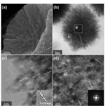
delve into the morphology and crystallinity inside these nanostructural spheres, we investigated the profiles of a cross section of those nano-spheres with the high-resolution SEM and TEM images (Fig. 2).
Fig. 2a shows the SEM image of a broken ED5 sphere. According to this profile of the cross section, one expects that
the nano-sphere is formed from various TiO2 nanorods
emanating from the center of the sphere. Hydrolysis of TiCl4
at low temperature producing rod-like rutile TiO2 has also
been reported.41The TEM images of the ED20 sphere shown in Fig. 2b–d confirm this mechanism of sphere formation. As clearly demonstrated in the TEM image shown in Fig. 2b, the nano-sphere has a solid structural feature in the inner sphere and a fine-hair, fibrous feature in the outer sphere. Fig. 2c and 2d show the corresponding high-resolution TEM images of ED20 in the outer and inner spheres, respectively. These HRTEM images indicate two important aspects of the formation of the nano-spheres: first, the nano-spheres are not amorphous – the lattice structures were unambiguously observed. The inset of Fig. 2c shows the distance between the adjacent lattice fringes to be 0.326 nm, which matches exactly the value for rutile TiO2in the (110) facet (JCPDS No. 21-1276).
Fig. 1 FESEM images of TiO2dandelion-like hierarchical rutile spheres (DHRS)
synthesized according to a ED-modified sol–gel procedure at 70uC showing spherical size/nm (a) 650 (ED5), (b) 550 (ED10), (c) 400 (ED15), (d) 300 (ED20), and (e) 200 (ED25) on varying the volume ratios of ED in aqueous solutions of fixed TiCl4volume. (f) shows a magnified image of DHRS of diameter 200 nm
(ED25).
Fig. 2 Typical SEM (a) and TEM (b–d) images of the TiO2dandelion-like
hierarchical rutile spheres (DHRS) showing internal morphologies and crystal phases of the nanostructures: (a) shows a highly magnified FESEM image of internal shell of a broken DHRS of diameter 650 nm (ED5) and (b) shows a cross-sectional profile of TEM image of DHRS of diameter 300 nm (ED20). (c) and (d) show high-resolution TEM images of the same DHRS (ED20) near the edge and the core, respectively, of the nano-sphere as the windows indicated in (b). The inset of (c) shows the fine structure of the lattice with rutile phase; the inset of (d) shows the corresponding electron diffraction pattern of a selected area near the core.
The XRD patterns shown in Fig. S1
3
also confirm the rutile crystalline phase of the ED0-ED25 spheres. Second, the orientation of the lattice was random in the inner sphere (Fig. 2d) but it became aligned toward the outward direction in the outer sphere (Fig. 2c). The electron diffraction pattern of a selected area (SAED) shown in the inset of Fig. 2d exhibits a set of rings instead of spots, consistent with the HRTEM image showing a random orientation of the rutile TiO2(110) lattice atthe spherical center.42,43Based on this structural information,
we conclude that the growth of the TiO2nano-spheres began
from nucleation at the spherical center forming nanorods along the [001] direction of the TiO2 rutile lattice spreading
outwards randomly; the titania DHRS, mono-disperse rutile TiO2 nano-spheres with a dandelion-like morphology, were
eventually produced.
Both TEM images and XRD patterns indicate that the titania nano-spheres as prepared had a rutile phase rather than being amorphous, even though the temperature of the reaction in air was only 70uC. Large concentrations44–46of TiCl
4 and small
pH44,47,48are two criteria to form rutile TiO2because only the
rutile-type nuclei exist in the solution under such condi-tions.45,48 For our sol–gel solutions prepared in the first
procedure, the concentration of TiCl4was as much as 0.9 mol
L21(5 mL TiCl4in 50 mL H2O). The hydration and hydrolysis
of TiCl4 in aqueous solution thus produced HCl at a large
concentration, resulting in a highly acidic aqueous solution to facilitate the formation of the seeding of the rutile titania. Crystal growth mechanism
Even though the formation of nanocrystalline rutile TiO2 at
low temperature with needle-like morphology is
reported,46,48,49 the uniformity of particle size was not well controlled. The hydrolysis and condensation in the dissolution and reprecipitation of titanium precursors occurred so rapidly that uniform and fine TiO2 particles were difficult to obtain,
because the nucleation and growth of titania cannot be separated into two steps in those conventional sol–gel methods.32,49 To solve this problem, researchers used ED serving as a chelating agent to form titanium glycolate to decrease significantly the rates of hydrolysis of titanium-alkoxide precursors.32,50,51 The titanium glycolate precursor was highly resistant to moisture for its slow hydrolysis, and mono-disperse titania colloids were produced when the titanium glycolate/ED solution was poured into a bath of acetone containing a little water.32,50 According to this
method, the crystal phase of the TiO2 nanoparticles as
prepared was amorphous; further calcinations at high tem-peratures are required for transition to a crystalline phase. In our approach, ED played an important role as a retardation agent in the second stage, and the fraction of ED in the ED/ water solvent is an essential factor to control the rates of hydrolysis, condensation and nucleation for final growth of crystals with a rutile phase. In Scheme 1 we propose a mechanism to rationalize the formation of mono-disperse DHRS TiO2as we have observed.
The formation of the DHRS TiO2of tunable size is considered
to involve six steps – (1) hydration and hydrolysis, (2) hydrolysis and retardation, (3) hydrolysis and condensation, (4) homo-geneous nucleation, (5) aggregation and rod-like crystal growth and (6) DHRS formation. In the first step, TiCl4was used instead
of titanium alkoxide precursors because the hydrolysis of TiCl4in
aqueous solution would produce HCl under highly acidic conditions to facilitate the formation of the rutile phase.44–49 When TiCl4was added at a large concentration to ice water at 0
uC, the titanium cation is believed to form a hexacoordinated monomer in aqueous solution.45,52 Hydration is accordingly
expected to occur at the beginning to form the octahedral complex [Ti(H2O)6]4+; hydrolysis proceeded to form the complex
[Ti(OH)n(H2O)62n](+42n), with n ¡ 6. To form the precursor of the
dispersed monomer complex in aqueous solution before condensation and nucleation, hydration and hydrolysis pro-ceeded at low temperature (0uC) with vigorous stirring.
To retard the hydrolysis and the following condensation, ED was added as a retardation agent in the second step. We expect that partially chelated titanium complex [Ti(OH)n(OCH2CH2O)m
(H2O)62n22m]42n22m, with n ¡ 6, m ¡ 3 and n + 2m ¡ 6, was
produced in the solution in the presence of ED. The glycolate ligand has a bridged chelating feature to prevent the approach of water molecules toward the central metal ion and is thus expected to slow significantly both the hydrolysis and the following condensation. We expect that the fraction of ED in the ED/H2O
solvent determines the values of m and n and thus controls the rates of hydrolysis and condensation occurring in the third step when the temperature was raised to 70 uC. Because the final products had only the rutile structure, formation of [TiO(H2O)5]2+
monomers is a key step in generating the rutile-type nuclei seeding in the solution for the succeeding condensation to occur.45The [TiO(H2O)5]2+complex might also exist in the first step but the
nucleation reaction would be slow at the low temperature; ED thus plays a key role to retard the hydrolysis of the
Scheme 1 Mechanism to form solvent-controlled nano-disperse TiO2dandelion-like hierarchical rutile spheres (DHRS).
[Ti(OH)n(H2O)62n](42n)complex so that homogeneous nucleation
occurs through condensation of the [TiO(H2O)5]2+complex in the
solution at a higher temperature (70uC). Once the nucleation occurred in a homogeneous manner, the spherical size became controllable through aggregation; mono-disperse TiO2 DHRS
were produced as schematically presented in Scheme 1. Effect of varied solvent
The effect of ED was examined with the use of pure water or other protic solvent in the second step. In the absence of ED (ED0), the TiCl4aqueous solution turned from transparent to turbid in ~20
min of heating; a white precipitate was rapidly produced because hydrolysis and condensation reactions were rapid. The corre-sponding SEM image in Fig. 3a (ED0) indicates that the size of the TiO2spheres was much larger (~1 mm) than that of other
ED-modified spheres with a broad distribution. In contrast, when ethanol (10%) served as a retardation agent in the solvent system of ethanol and water, irregular TiO2aggregates were produced
with particle size in the range 50–200 nm (Fig. 3b).
For diols, only ethan-1,2-diol (ED10) and propan-1,3-diol (10%) have an ability to tune the size so as to produce mono-disperse TiO2nano-spheres, as can be seen in the SEM images
shown in Fig. 3c and 3d, respectively. When the central hydrocarbon chains of the diols were extended beyond three carbons, e.g., in butan-1,4-diol and pentan-1,5-diol, the control of the formation of uniform size was lost; the SEM images (Fig. 3e and 3f) exhibit large and small spheres with size over a broad range. The 400 nm size of nanospheres generated from
propan-1,3-diol is smaller than that, 550 nm, generated from ED10, indicating that the rates of hydrolysis and condensation were much smaller for the former than the latter. The bridging diol units with three carbon atoms chelated the titanium central ion more efficiently than the ethan-1,2-diol units, effectively to prevent the approach of water molecules and to retard the hydrolysis. When the number of carbon atoms increased beyond three, the diol with a bidentate chelating structure formed a larger ring, which is both thermodynami-cally and sterithermodynami-cally unfavorable to stabilize such a bidentate complex. As a result, the retardation of hydrolysis vanished so that a random distribution was produced for the solvent systems based on butan-1,4-diol (Fig. 3e) and pentan-1,5-diol (Fig. 3f), similar to the case of pure water (Fig. 3a).
Photovoltaic performance as a scattering overlayer
The DSSC devices were made with identical components – transparent TiO2 active layer (~14 mm), Z907 dye, iodide/
triiodide electrolyte and Pt counter electrode – except that varied mono-disperse titania DHRS, ED5-ED25, of the same thickness (~5 mm) were used as LSL for DSSC. The current– voltage ( J-V) characteristics and the corresponding IPCE action spectra of these devices are shown in Fig. S2a and S2b, ESI
3
, respectively, and the photovoltaic parameters are summarized in Table S13
. The photovoltaic performance of these devices is similar: the best device (ED20) arose from its short-circuit photocurrent density (JSC) greater than the others because of asuperior light-scattering effect for DHRS of spherical size ~300 nm, consistent with the results obtained from theoretical simulations.20 The device with the LSL made of ED20 was hence used to compare with the devices with the LSL made of three TiO2scattering pastes commercially available.
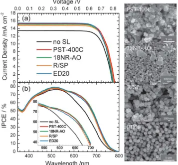
Fig. 4a and 4b show a typical set of J-V curves (working electrode a) and the corresponding IPCE action spectra of the devices with the LSL made of PST-400C (CCIC), 18NR-AO (Dyesol), R/SP (Solaronix) and ED20 (present work); the photovoltaic performances of each device were measured based on three identical working electrodes (labeled a–c, Table S2, ESI
3
), but only the results of device a are displayed in the plots and the related photovoltaic parameters are summarized in Table 1. The top-view SEM images of these LSL are shown in the right panel of the figures; the side-view SEM images of these films are shown in Fig. S3a–S3d3
to display the double-layer structure with an optimal film thickness (14 + 5 mm).53 From the morphological point of view, the PST-400C paste consists of irregular large aggregates (size ~400 nm) mixed with small nanoparticles (size ~20 nm), the 18NR-AO paste contains small nanorods (size ~20 nm) mixed with large crystals (size 200–400 nm), and the R/PS paste comprises nanoparticles (size 100–200 nm); no such commercial TiO2colloid has uniform size like ED20, but the effects of these LSL on photovoltaic performance are similar; the efficiencies of power conversion exhibited the order ED20 ~ PST-400C . 18NR-AO . R/SP, with the best devices (ED20 and PST-400C) attaining g = 9.3%, and the worst device (R/SP) attained g = 9.1%; the differences in photovoltaic performances of these devices were within the experimental uncertainties. Note that the reference device without a LSL shows much lower JSCthan
Fig. 3 FESEM images of titania nanospheres generated with various solvents in the second hydrolysis: (a) pure water, (b) ethanol, (c) ethan-1,2-diol (ED), (d) propan-1,3-diol, (e) butan-1,4-diol, and (f) pentan-1,5-diol, with the same sol– gel procedure and volume ratio (cosolvent/H2O/TiCl4= 10/90/5). Each scale bar
indicates 1 mm.
the others, giving a much poorer power conversion efficiency g = 8.2%.
The IPCE spectra shown in Fig. 4b indicates that the LSL effect enhances the efficiencies in the spectral region of 550– 750 nm, which is consistent with the results predicted from the theoretical simulation.13,20The inset of Fig. 4b shows enlarged IPCE spectra for detailed comparison of their performance in the 550–700 nm region. The ED20 device with mono-disperse DHRS as LSL exhibited a slightly larger JSCthan those of other
devices because of a superior scattering effect at wavelengths ,550 nm and .700 nm, which might be rationalized by the UV-Vis reflectance spectra shown in Fig. S4
3
: the DHRS has higher reflectance than the others because of higher refractive index for the rutile phase than for the anatase phase.22As the ED20 device performed similarly to those made of expensive commercial TiO2 scattering pastes, the LSL made of DHRStitania colloids provides a cheap alternative as a key material for future DSSC commercialization.
Conclusions
Mono-disperse TiO2dandelion-like hierarchical rutile spheres
(DHRS) were produced with a solvent-controlled sol–gel method at a low temperature. The synthetic procedure is divisible into three simple steps using only TiCl4, water and a specific diol
solvent mixture with water. First, the TiCl4precursor and water
were mixed in a volume ratio 1/10 in an ice bath and stirred for 1 h to generate a hydrated titanium complex. Second, a diol-water solvent mixture of volume the same as that of water in the first step was added into the transparent TiCl4 aqueous solution
near 298 K and stirred for another hour to form a hydrated titanium diol complex to retard the hydrolysis and condensa-tion. Third, when the temperature of the solution as prepared was raised to 70 uC for 2 h, the retarded hydrolysis and condensation led to homogeneous nucleation of a crystalline rutile-type structure to generate a rod-like seed; aggregation followed by growth of rod-like crystals along the [001] facet direction of the rutile phase extending randomly from the core of the seed to form the mono-disperse rutile TiO2nanospheres
with a dandelion-like hierarchical structure.
Among the tested solvents, only ethan-1,2-diol (ED) and propan-1,3-diol mixed with water have the ability to form the DHRS of uniform size, indicating that these diols with two or three carbons are amenable to form a hydrated titanium diol complex effectively to retard the subsequent hydrolysis and condensation so that nucleation occurs in a homogeneous manner to generate mono-disperse nano-spheres, according to our experiments. The size of DHRS is well controlled to give average diameter 650, 550, 400, 300 and 200 nm with volume ratio of ED with respect to the total water as 5% (ED5), 10% (ED10), 15% (ED15), 20% (ED20) and 25% (ED25), respectively. The DSSC device fabricated with Z907 dye using the DHRS of size ~300 nm (ED20) as light-scattering layer (LSL) achieved g = 9.3%, which is comparable with or superior to that of a device made of an expensive commercial LSL TiO2paste – PST-400C from (CCIC)
g = 9.3%, 18NR-AO (Dyesol) g = 9.2% and R/SP (Solaronix) g = 9.1%. The present work provides a non-hydrothermal approach to synthesize mono-disperse rutile TiO2in three simple steps at
low temperature using only three inexpensive initial materials, whereby the reported method becomes feasible for mass production and offers great opportunities not only as LSL for DSSC but also for other industrial applications such as sensing, photocatalysis, photovoltaics, water splitting, photonic crystals, electrochromic devices and so forth.49
Acknowledgements
National Science Council of Taiwan and Ministry of Education of Taiwan, under the ATU program, provided support for this project.
Table 1 Amount of dye-loading (DL) and optimized photovoltaic parameters of devices made of Z907 dye and various scattering TiO2pastes – PST-400C,
18NR-AO, R/SP and ED20 – with the same transparent TiO2films (labeled as no SL)
and TiCl4post-treatment under simulated AM-1.5G illumination (power 100
mW cm22) and active area 0.16 cm2with a shadow mask 0.25 cm2
LSL DL JSC VOC FF g /nmol cm22 /mA cm22 /mV /% no SL 204 13.5 797 0.758 8.2 PST-400C 235 15.2 819 0.750 9.3 18NR-AO 252 15.1 799 0.760 9.2 R/SP 226 14.7 813 0.761 9.1 ED20 242 15.3 803 0.754 9.3
Fig. 4 Optimized photovoltaic properties: (a) current–voltage characteristics and (b) corresponding IPCE action spectra of devices sensitized with Z907 dye and made of varied TiO2scattering pastes – PST-400C, 18NR-AO, R/SP and ED20
(thickness ~5 mm) on top of a transparent TiO2active layer of thickness ~14 mm
(labeled as no SL) with TiCl4post-treatment under irradiation (one-sun
AM-1.5G). The SEM images corresponding to these LSL appear in the right panel.
References
1 B. Oregan and M. Gra¨tzel, Nature, 1991, 353, 737–740. 2 M. K. Nazeeruddin, A. Kay, I. Rodicio, R. Humphry-Baker,
E. Mu¨ller, P. Liska, N. Vlachopoulos and M. Gra¨tzel, J. Am. Chem. Soc., 1993, 115, 6382–6390.
3 M. Gra¨tzel, Nature, 2001, 414, 338–344.
4 A. Hagfeldt, G. Boschloo, L. C. Sun, L. Kloo and H. Pettersson, Chem. Rev., 2010, 110, 6595–6663.
5 M. K. Nazeeruddin, F. D. Angelis, S. Fantacci, A. Selloni, G. Viscardi, P. Liska, S. Ito, T. Bessho and M. Gra¨tzel, J. Am. Chem. Soc., 2005, 127, 16835–16847.
6 Q. Wang, S. Ito, M. Gra¨tzel, F. Fabregat-Santiago, I. Mora-Sero, J. Bisquert, T. Bessho and H. Imai, J. Phys. Chem. B, 2006, 110, 25210–25221.
7 C.-Y. Chen, M. K. Wang, J.-Y. Li, N. Pootrakulchote, L. Alibabaei, C. Ngoc-Ie, J.-D. Decoppet, J.-H. Tsai, C. Gra¨tzel, C.-G. Wu, S. M. Zakeeruddin and M. Gra¨tzel, ACS Nano, 2009, 3, 3103–3109.
8 Q. J. Yu, Y. H. Wang, Z. H. Yi, N. N. Zu, J. Zhang, M. Zhang and P. Wang, ACS Nano, 2010, 4, 6032–6038.
9 T. Bessho, S. M. Zakeeruddin, C.-Y. Yeh, E. W.-G. Diau and M. Gra¨tzel, Angew. Chem., Int. Ed., 2010, 49, 6646–6649. 10 Y.-C. Chang, C.-L. Wang, T.-Y. Pan, S.-H. Hong, C.-M. Lan,
H.-H. Kuo, C.-F. Lo, H.-Y. Hsu, C.-Y. Lin and E. W.-G. Diau, Chem. Commun., 2011, 47, 8910–8912.
11 A. Yella, H.-W. Lee, H. N. Tsao, C. Yi, A. K. Chandiran, M. K. Kazeeruddin, E. W.-G. Diau, C.-Y. Yeh, S. M. Zakeeruddin and M. Gra¨tzel, Science, 2011, 334, 629–634.
12 L.-L. Li and E. W.-G. Diau, Chem. Soc. Rev., 2013, DOI: 10.1039/C2CS35257E.
13 Q. Zhang, D. Myers, J. Lan, S. A. Jenekhe and G. Cao, Phys. Chem. Chem. Phys., 2012, 14, 14982.
14 C.-C. Chen, H.-W. Chung, C.-H. Chen, H.-P. Lu, C.-M. Lan, S.-F. Chen, L.-Y. Luo, C.-S. Hung and E. W.-G. Diau, J. Phys. Chem. C, 2008, 112, 19151–19157.
15 L.-L. Li, C.-Y. Tsai, H.-P. Wu, C.-C. Chen and E. W.-G. Diau, J. Mater. Chem., 2010, 20, 2753–2758.
16 L.-L. Li, Y.-J. Chen, H.-P. Wu, N. S. Wang and E. W.-G. Diau, Energy Environ. Sci., 2011, 4, 3420–3425.
17 L.-L. Li, C.-W. Chang, H.-H. Wu, J.-W. Shiu, P.-T. Wu and E. W.-G. Diau, J. Mater. Chem., 2012, 22, 6267–6273.
18 S. Hore, P. Nitz, C. Vetter, C. Prahl, M. Niggemann and R. Kern, Chem. Commun., 2005, 2011–2013.
19 S.-H. Han, S. Lee, H. Shin and H. S. Jung, Adv. Energy Mater., 2011, 1, 546–550.
20 J. Ferber and J. Luther, Sol. Energy Mater. Sol. Cells, 1998, 54, 265–275.
21 S. Hore, C. Vetter, R. Kern, H. Smit and A. Hinsch, Sol. Energy Mater. Sol. Cells, 2006, 90, 1176–1188.
22 H.-J. Koo, J. Park, B. Yoo, K. Yoo, K. Kim and N.-G. Park, Inorg. Chim. Acta, 2008, 361, 677–683.
23 Z.-S. Wang, H. Kawauchi, T. Kashima and H. Arakawa, Coord. Chem. Rev., 2004, 248, 1381–1389.
24 H.-J. Koo, Y. J. Kim, Y. H. Lee, W. I. Lee, K. Kim and N.-G. Park, Adv. Mater., 2008, 20, 195–199.
25 D. Chen, F. Huang, Y.-B. Cheng and R. A. Caruso, Adv. Mater., 2009, 21, 2206–2210.
26 F. Huang, D. Chen, X. L. Zhang, R. A. Caruso and Y.-B. Cheng, Adv. Funct. Mater., 2010, 20, 1301–1305.
27 F. Sauvage, D. Chen, P. Comte, F. Huang, L.-P. Heiniger, Y.-B. Cheng, R. A. Caruso and M. Gra¨etzel, ACS Nano, 2010, 4, 4420–4425.
28 J.-Y. Liao, B.-X. Lei, D.-B. Kuang and C.-Y. Su, Energy Environ. Sci., 2011, 4, 4079–4085.
29 H. Zhang, Y. Han, X. Liu, P. Liu, H. Yu, S. Zhang, X. Yao and H. Zhao, Chem. Commun., 2010, 46, 8395–8397. 30 W. Yang, J. Li, Y. Wang, F. Zhu, W. Shi, F. Wan and D. Xu,
Chem. Commun., 2011, 47, 1809–1811.
31 X. Wu, Z. G. Chen, G. Q. Lu and L. Z. Wang, Adv. Funct. Mater., 2011, 21, 4167–4172.
32 Xuchuan Jiang, Thurston Herricks and Younan Xia, Adv. Mater., 2003, 15, 1205–1209.
33 I. G. Yu, Y. J. Kim, H. J. Kim, C. Lee and W. I. Lee, J. Mater. Chem., 2011, 21, 532–538.
34 Y.-C. Park, Y.-J. Chang, B.-G. Kum, E.-H. Kong, J. Y. Son, Y. S. Kwon, T. Park and H. M. Jang, J. Mater. Chem., 2011, 21, 9582–9586.
35 Y. Chen, F. Huang, D. Chen, L. Cao, X. L. Zhang, R. A. Caruso and Y.-B. Cheng, ChemSusChem, 2011, 4, 1498–1503.
36 S. Ito, P. Chen, P. Comte, M. K. Nazeeruddin, P. Liska, P. Pechy and M. Gra¨tzel, Progr. Photovolt.: Res. Appl., 2007, 15, 603–612.
37 C. J. Barbe´, F. Arendse, P. Comte, M. Jirousek,
F. Lenzmann, V. Shklover and M. Gra¨tzel, J.Am. Ceram. Soc., 1997, 80, 3157–3171.
38 S. Ito, T. N. Murakami, P. Comte, P. Liska, C. Gra¨tzel, M. K. Nazeeruddin and M. Gra¨tzel, Thin Solid Films, 2008, 516, 4613–4619.
39 Y. J. Kim, M. H. Lee, H. J. Kim, G. Lim, Y. S. Choi, N.-G. Park, K. Kim and W. I. Lee, Adv. Mater., 2009, 21, 3668–3673.
40 D. H. Chen, L. Cao, F. Z. Huang, P. Imperia, Y. B. Cheng and R. A. Caruso, J. Am. Chem. Soc., 2010, 132, 4438–4444. 41 N.-G. Park, G. Schlichtho¨rl, J. van de Lagemaat, H. M. Cheong, A. Mascarenhas and A. J. Frank, J. Phys. Chem. B, 1999, 103, 3308–3314.
42 S. K. Das, M. K. Bhunia and A. Bhaumik, Dalton Trans., 2010, 39, 4382–4390.
43 D. Eder and A. H. Windle, J. Mater. Chem., 2008, 18, 2036–2043.
44 H. Cheng, J. Ma, Z. Zhao and Limin Qi, Chem. Mater., 1995, 7, 663–671.
45 Z. Yanqing, S. Erwei, C. Zhizhan, L. Wenjun and H. Xingfang, J. Mater. Chem., 2001, 11, 1547–1551. 46 Y. Li, Y. Fan and Yi Chen, J. Mater. Chem., 2002, 12, 1387–1390. 47 M. Wu, G. Lin, D. Chen, G. Wang, D. He, S. Feng and R. Xu,
Chem. Mater., 2002, 14, 1974–1980.
48 S. Yin, H. Hasegawa, D. Maeda, M. Ishitsuka and T. Sato, J. Photochem. Photobiol., A, 2004, 163, 1–8.
49 X. Chen and S. S. Mao, Chem. Rev., 2007, 107, 2891–2959. 50 M. Pal, J. G. Serrano, P. Santiago and U. Pal, J. Phys. Chem.
C, 2007, 111, 96–102.
51 V. N. Krasil’nikov, A. P. Shtin, O. I. Gyrdasova, E. V. Polyakov and G. P. Shveikin, Nanotechnol. Russ., 2008, 3, 1065–1069. 52 V. D. Hildenbrand, H. Fuess, G. Pfaff and P. Reynders, Z.
Phys. Chem., 1996, 194, 139–150.
53 J.-W. Shiu, C.-M. Lan, Y.-C. Chang, H.-P. Wu, W.-K. Huang and E. W.-G. Diau, ACS Nano, 2012, DOI: 10.1021/ NN3042418.