I084 IEEE PHOTONICS TECHNOLOGY LETTERS, VOL. I, NO. 9, SEPTEMBER 1995
Demonstration
of
In-service SuDervisorv
Repeaterless Bidirectional Wavelength-
Division-Multiplexing Transmission System
Y. K.
Chen, W.Y. Guo, S.
Chi, and W. I. Way, Senior Member, IEEEAbstract- An in-service supervisory repeaterless bidirectional wavelength-division-multiplexing (WDM) transmission system using optical fiber amplifiers is demonstrated for the first time. The system supervision by an optical time domain reflectometer (OTDR) is achieved without degrading the 2.5 Gb/s service
over a bidirectional six-WDM-channel 200-km single-fiber link.
Negligible system penalties of dispersion and counter-directional transmission crosstalk are observed.
I. INTRODUCTION
EPEATERLESS long-distance fiber transmission sys-
R
tems using erbium-doped fiber amplifiers (EDFA’s) as a transmitter power amplifier and/or as a receiver preamplifier have many applications, in which cases it is infeasible or impossible to have an in-line amplifier, such as island-hopping and intracity links. Bidirectional transmission over a single fiber offers the advantages of double capacity and interactivity, and the wavelength division multiplexing (WDM) technique is very useful for further increasing the system capacity. Several repeaterless bidirectional single-channel transmissions have been reported recently [l], [2], but the issues of repeaterless bidirectional multichannel WDM transmission have not yet been studied. Furthermore, it is important to facilitate in- service supervision and fiber fault-location [3], [4] in the system while the ever-growing traffic transmits bidirectionally over a single fiber.In this letter, an in-service supervisory repeaterless bidirec- tional six-WDM-channel transmission over a 200-km single- fiber link is demonstrated. At each site, an optical power amplifier and a preamplifier were used and the 1.53/1.55-pm WDM multiplexer included to offer the access point for optical time domain reflectometer (OTDR) supervision. To our knowledge, this is the first repeaterless bidirectional trans- mission demonstration not only with multichannel WDM operation but also with in-service supervisory capability. No degradation of 2.5-Gb/s service is found during the OTDR supervision. Negligible system penalties of dispersion and counter-directional amplified transmission are observed.
Manuscript received February 10, 1995; revised May 12, 1995. Y. K. Chen and W. Y. Guo are with the Telecommunication Laboratories, Ministry of Transportation and Communications, Taiwan, Republic of China. S. Chi and W. I. Way are with the Institute of Electro-Optical Engineering and Center for Telecommunications Research, National Chiao-Tung Uuiver-
sity, Taiwan, ROC.
IEEE Log Number 9413505.
Node A
Node
B
,
Transmitters
I 1
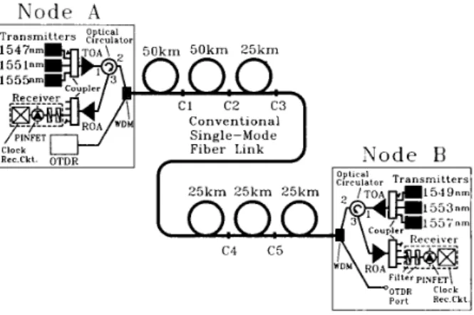
Fig. 1. In-service supervisory repeaterless bidirectional WDM transmission system. TOA: optical power amplifier. ROA: optical pre-amplifier. OTDR: op-
tical time domain reflectometer. WDM: the 1.53/1.55-pm WDM multiplexer.
11. SYSTEM DESCRIPTIONS
The experimental arrangement is depicted in Fig. 1. At each optical node (A or B), three DFB-laser channel signals are delivered to the 4 x 1 optical coupler at -6 dBm per channel. The corresponding channel wavelengths are 1547, 155 1, 1555 nm at node A and 1549, 1553, 1557 nm at node B. A 2.5- Gb/s pseudorandom
z3l-
1 NRZ electrical signal was used to modulate a chirp-adjustable Ti : LiNbOy Mach-Zehnder external modulator for the channel at 1551 nm. Extemal modulation was used to minimize the dispersion limitation. The other DFB lasers at nodes A and B were running in CW mode. A transmitter power amplifier (TOA) was employed after the coupler in order to provide the sufficient signal powers to the transmission line. The TOA is a 980-nm single- pumped EDFA yielding about+
12 dBm total output power. A polarization-independent three-port optical circulator was used to launch the TOA-amplified channel signals into the transmission link and to receive the incoming opposite channel signals. Each circulator has such features: 1) low reflection of less than -55 dB, 2) low insertion losses of about 1.3 dB for both port #1 to #2 and port #2 to #3, and 3) high isolations of about 35 dB for both port #2 to #1 and port #3 to #2, and about 50 dB for port #3 to #l. The received WDM channel signals were amplified by a receiver optical preamplifier (ROA), split by a 1 x 4 coupler, and then demultiplexed by a cascade of two optical bandpass filters. The demultiplexed channel 104-1135/95$04,00 0 1995 IEEECHEN et al.: IN-SERVICE SUPERVISORY REPEATERLESS BIDIRECTIONAL WDM TRANSMISSION SYSTEM 1085 S P E C T R U M -19 -29 -39 1526.8 155 1. enm 1576. e S P E C T R U M -2 1
I
H:- 2-nmlDiV.
. _
1 1 I ,__._ _
Efl
"I- .
, - * . -41 , ,. -
-51.
,.. -61 1541.8 155 1. Bnm 1561.8 Fig. 2.(c) after the 1.0-nm filter, and (d) after the 0.4-nm filter
Evolution of the optical spectrum of forward-transmitted WDM signals in the site of node B: (a) before preamplifier, (b) after preamplification,
signal was then detected by a PINFET receiver, processed by a clock recovery circuit, and finally measured by the bit-error- rate (BER) test set. The 980-nm single-pumped ROA has an optical gain of 25.2 dB and noise figure of 4.2 dB. The filter cascade was used to select the desired channel signal and to reject the other channel signals and the optical noise. The front filter with 1.0-nm 3-dB bandwidth and 2.2-dB loss and the rear one with 0.25-nm 3-dB bandwidth and 3.0-dB loss. The receiver sensitivity at the position of ROA was -41.4 dBm at BER of 1 x lo-' for 2.5-Gb/s data rates.
A minor-modified HP8146A OTDR [5] using a suitable 1535-nm DFB laser diode was used in the experiment. The OTDR has a single-way dynamic range of 25 dB and an event resolution of 1.5
km.
A 1.53/1.55-pm WDM multiplexer was inserted at the output port of circulator to offer the OTDR in-service supervisory operation in each node. Moreover, this multiplexer can suppress the 1.53-pm Rayleigh back scattering of the forward amplified spontaneous emission (ASE) noise of the transmitted TOA at the same node to maintain the normal operation of the 1535-nm OTDR probe signals in the fiber link. Each 1.53/1 .%-pm WDM multiplexer has a channel isolation of about 29-dB, back-reflection of -42dB,
and insertion loss of about 1.0 dB. The high isolation and low back-reflection features of WDM's offer good demultiplexing capability to prevent any mutual crosstalk between the bidirectional WDM service channels and OTDR supervision channel. Six spools of conventional single-mode fiber, assembled by 50+
50+
25+
25+
25+
25km
(from node A to node B) and with a total length of 200 km, was well connected with optical matched gel for the transmission fiber link. The link loss was about 47 dB, including the losses of one fiber span (0.205dB/km), two WDM multiplexers, two circulators, and fiber connections.
111. RESULTS AND DISCUSSIONS
The measured power level of each transmitted WDM chan- nel signal was about +7.2 dBm and +7.5 dBm for nodes A and B, respectively. Fig. 2(a) to 2(d) show the spectral evolution of the transmitted WDM signals from node A to node B: before the ROA, after the ROA, after the 1.0-nm filter, and after the 0.25-nm filter, respectively. Note that the power of each counter-directional channel (i.e., 1549, 1553, and 1557 nm) was 10 dB higher than that of re- ceived channels from node A as shown in Fig. 2(a). The counter-directional crosstalk was mainly cause by Rayleigth backscattering from the transmission fiber span, reflection from the 1.53/1.55-pm WDM coupler, and residual reflections in the fiber span. Here, assume the Rayleigh backscattering reflectivity of the conventional single-mode fiber is -32 dB [6], then we can calculate that the crosstalk power level of each counter-directional channel before the ROA at node B is about -29.4 dBm. This calculated value is fairly close to the measure results in Fig. 2(a). However, the calculated power lever of other crosstalk effect of reflections is about 7 dB lower than that of the Rayleigh backscattering crosstalk. Although these mixed WDM channels were amplified simultaneously by an preamplifier at node B (see Fig. 2(b)), any desired received channel can be successfully selected by the cascade of two optical filters as illustrated in Fig. 2(c) and (d). The optical crosstalk ratio of the demultiplexed channel was about 33 dB (see Fig. 2(d)). Therefore, sufficient optical narrow band-filtering is required for demultiplexing the bidirectional
1086 IEEE PHOTONICS TECHNOLOGY LETTERS, VOL. I, NO. 9, SEPTEMBER 1995 -4- -5- -6- -7- -0- -9- 10- Back-to-Back Single Ch#2 6 chs. (OTDR OFF) -s- --)t 6 chs. (OTDR ON) -1$, -44 4 3 -42 -ii -io -49
Received Power,dBm, of Channel 2
Fig. 3. System bit-error-rate (BER) of channel 2 (1551 nm) at 2.5 Gb/s for six-WDM-channel bidirectional transmission with OTDR supervision on and
O f f .
WDM channels, otherwise, the dominant Rayleigh backscat- tering counter-directional crosstalk will degrade the system performance.
Fig. 3 shows the BER performance of the in-service re-
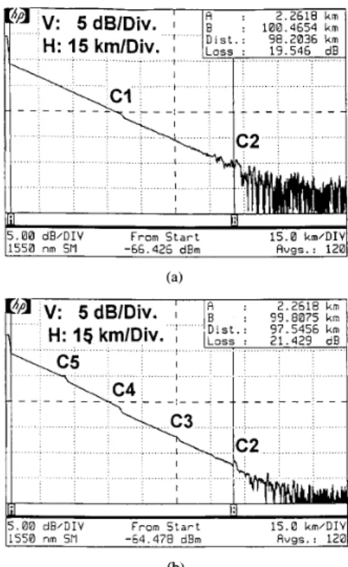
peaterless bidirectional WDM transmission system with OTR operation on and off. About 0.2 dB dispersion power penalty was observed between the signal-channel (here, the second forward-transmitted channel at 155 1 nm) 200-km transmission and back-to-back performance at BER of 1 x lo-’. Negli- gible degradation of system performance due to the OTDR supervision operation was found. The BER floor was not observed below 1 x BER for bidirectional six-WDM- channel transmission. About 0.1 dB power penalty (@ BER of 1 x lo-”), which was introduced by the Rayleigh backscat- tering from the counter-directional amplified transmission and residual optical reflections, was observed, Fig. 4(a) and (b) show the in-service supervision OTDR traces of the system link monitored (with two-minute measurements) at node A and B, respectively. Note that the position of connection points (Cl, C2, C3, C4, and C 5 ) in Fig. 4(a) and (b) coincides with the length of physical link layout in Fig. 1. When a high- dynamic-range OTDR is available, for example, 42 dB, the supervision operation can be realized in either one node.
IV. CONCLUSION
In summary, we have demonstrated, for the first time, an in-service supervisory repeaterless bidirectional transmission system using a pair of optical power amplifier and preamplifier and a WDM’ed OTDR at each site. We found that sufficient optical narrow-band filtering is required for demultiplexing the bidirectional WDM channels, otherwise, the dominant Rayleigh backscattering counter-directional crosstalk will de- grade the system performance. In our demonstration, no degra- dation of 2.5 Gb/s service channels was found for the OTDR supervision over the bidirectional six-WDM-channel 200-km
I . . . , . 1 5 . 0 km/DIV 5.00 dB/DIV From S t a r t 1550 n m SM -66.426 dBm Avgs.: 120 1 5 . 0 km/DIV 5 . 0 6 dB/DIV From S t a r t 1556 nm SPI -64 478 dBm Pugs. : 128 (b) Fig 4
ports at (a) node A and (h) node B.
OTDR supervision traces of the system monitored from the access
single fiber link. Negligible system penalties of dispersion and counter-directional transmission crosstalk were observed. The system technology may find many applications for high- capacity inter-island undersea, island hopping, and intracity links with no in-line amplifiers allowed.
REFERENCES
[ 11 K. Kannan and S. Frisken, “Unrepeatered bi-directional transmission system over a single fiber using optical fiber amplifiers,” IEEE Photon.
Technol. Lett., vol. 5 , pp. 7 6 7 9 , 1993.
[2] R. J. Orazi and M. N. McLandrich, “Bi-directional transmission at 1.55 microns using fused fiber narrow channel wavelength division multiplexers and erbium-doped fiber amplifiers,” IEEE Photon. Technol.
[ 3 ] Y . W. Lai, Y . K. Chen, and W. I. Way, “Novel supervisory technique us-
ing wavelength-division-multiplexed OTDR in EDFA repeatered trans- mission systems,’’ IEEE Photon. Technol. Lett., vol. 6, pp. 44-49. 1994.
[4] Y. K. Chen, W. Y. Guo, W. I. Way, and S. Chi, “Simultaneously in-service fault-locating and EDFA-monitoring supervisory transmis- sion in EDFA repeatered systems,” Electron. Lett., vol. 30, no. 25,
pp. 2145-2146, 1994.
[ 5 ] Y. K. Chen and S . Chi, “Novel technique for all-haul optical time domain reflectometry using optical amplifier and switches,” in Tech.
Dig. CLEO ’94, Paper ThI40, 1994.
[6] J. L. Gimlett, M. Z. Iqhal, N. K. Cheung, A. Righetti, F. Fontana, and G. Grasso, “Observation of equivalent Rayleigh scattering mirrors
in lightwave systems with optical amplifiers,” IEEE Photon. Technol.
Lett., vol. 2, pp. 211-213, 1990.