Magnetic Analysis of A Micromachined Magnetic Actuator
Using the Finite Element Method
C. H. Ko, J. J. Yang*, J. C. Chiou, S. C. Chen*, and T. H. Kao*
Department of Electrical and Control Engineering
National Chiao Tung University, HsinChu, 300-1 0, Taiwan
Phone
: 886-3-5731881FAX
:886-3-5715998
E-Mail : [email protected]
*
MEMS Research Div. Mechanical Industry Research Laboratories
Industrial Technology Research Institute, HsinChu, 3 10, Taiwan
Abstract
In this paper, a parametrical method is developed to design a magnetic microactuator. The method is
based on modeling the magnetic microactuator using the finite element analysis software that can be used to calculate the energy density and magnetic force. Here, the concept of design on experiments (DOE) is used to identify critical parameters that affect the performances of the electromagnetic
microactuator. Numerical simulation results from a series of DOE have indicated that the dimension of core and the magnetic material block have the influence on planar electromagnetic actuators. When the
length of the magnetic components is equal to that of outer diameter of coil circuit, we obtain the best efficiency in magnetic force. Furthermore, when we increase the thickness of the magnetic materials block or shorten the distance between the coils and magnetic material block, the magnetic force will
increase dramatically. In addition, we can achieve a great magnetic force when the combination ratio of
the length of the core is half of the magnetic material block. Simulation results have shown that electromagnetic actuators with high aspect ratio planar coil could sustain higher electrical current that consequently increases the magnetic force. During the realistic fabrication, the thick resist patterning
and electroplating technologies is used to fabricate the above-mentioned electromagnetic microactuator. Experimental results indicated that the magnetic force follows closely to the simulation results.
I. Introduction
The main advantage of using an electromagnetic principle for microactuation is its capability of providing higher forces over relatively large distances. Note that the magnetic actuation methods not
only offer a solution for generating repulsive forces but also giving forces that can be driven in both
directions. Furthermore, the microactuation with electromagnetic principle also has the features of high
frequency and low driving voltage. In conclusion, the electromagnetic microactuators have great
potential in its future applications.
In the past, the progress of developing a useful magnetic microactuator is limited due to the fact that the manufacturing process of magnetic microactuators is not compatible with that of IC manufacturing process. However, microactuators based on electromagnetic principle have been developed recently for
various types of microsystems, mainly because of the progress in the process to deposit magnetic
materials and coils on the silicon substrate [1]. For different actuation purpose, these electromagnetic
microactuators have successfully applied to the micropump [2], microvalve [3], microrelay [4,5],
micromotor[6], and other similar microactuators [7,8,9].
Note that the magnitude of electromagnetic force is highly related to the design criterions that may included the number of the coils, the size of the core, the deposited magnetic material block and the distance between the coils and the magnetic material block. With this in mind, we start this paper by
emphasizing the theoretical background of the magnetic microactuator. Here the model of the magnetic
microactuator is established by using the finite element method that provides the energy density and
magnetic force of the magnetic fields. Upon obtaining the model, the concept of design on experiments (DOE) is used to identify critical parameters that affect the performances ofthe magnetic microactuator.
Note that, these critical parameters are found by assigning a series of testing points in the designed region. With these critical parameters, we can design the magnetic microactuator correctly. In microfabrication, we use the AZ4620 resist material and electroplating materials to fabricate a
magnetic microactuator. Discussions and evaluations were made on the experiments and numerical
solutions. These results provide valuable inside in designing a new electromagnetic microactuator.
II. Theoretical Analysis of the Electromagnetic Microactuator
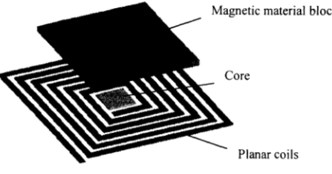
A typical electromagnetic microactuator usually contains two main parts —theplanar coils and the
magnetic material block (sometimes core becomes the third part) as shown in Fig. I .Theoperation of the actuator is given as follows : when the electrical current is applied to the coils, a magnetic field is generated around the coils that act perpendicular to the plane of the coils. When we applied the magnetic field on the magnetic material block attached on the deformable film structure, a magnetic
force is generated. This magnetic force can be used to deform the film structure upwards/downwards in
the vertical direction. The Calculations [1,10] of the generated magnetic field strength H can be
can be written as follows [7]:
M = fJrH
where Pr themagnetic susceptibility of the magnetic block. In the case the material is in its linear
region, the susceptibility can be considered to be independent from the field. The magnetic force
density f can be expressed as:
f=v(M.H)
Furthermore, taking the vertical component of f (the component in the z-dimension) and integrating it
over the volume V of the magnetic block:
F çd(M.Hz)dv
dztheresult yields the total magnetic vertical force F exercised on the deformable structure. Magnetic material block
Core
Planar coils
Fig. I The electromagnetic microactuator
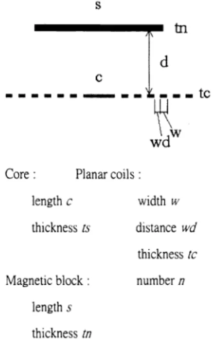
In order to obtain the insight of the mechanism, we analyze the magnetic problem using the general-purpose finite element software ANSYS 5.4. To simplify the analysis, the planar coil is assumed to be axial symmetrical. The ANSYS PLANE53 2D element has been performed to obtain the forces acting
on the magnetic material block. The parameters of the device are shown in Fig. 2. The material of the coils is Cu by assuming the effective permeability tr =1 .Themagnetic material block and core are made by NiFe with an effective permeability tr3OO. In the finite element model, we need to establish the planar coil, the core, the magnetic material block and the substance between the two (it will be air in the present analysis). We use 2D infinite boundary element to simulate the far field boundary condition of the model. Fig.4 shows the magnetic density B generated by the planar coil. As shown in the figure, the flux lines start from the coils, move upward to the magnetic block and finally extend to
the air. There exists a maximum density (0. 16T) on the tip of the magnetic material block at 1=1.5(A),
s200, d15, c100, n6 and w2OQim). Note that the force between planar coil and the magnetic block is about 11 .45Q.tN). Planar coils: width w distance wd thickness IC number n
Fig. 2. The parameters of the device.
III. Numerical Simulation Results
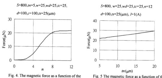
To extract the parameters that affect the design of the electromagnetic microactuator, firstly, we focus our study on the relation between the number of the coils n and the resulting magnetic force.
Assuming that the length of the magnetic material block equals to 800.tm, the length of coil equals to 1 00.tm, the electrical current equals to I A, the numerical simulation results of varying the number of
the coils n to the generated force are shown in Fig.4. Note that the magnetic force is increased as n is
increased. When n is in the range between 4 and 8, the relationship between the force and the number of coils is liner. However, when n reaches 10, the force increases slowly that gave the maximum value at approximately 21 .8 .tN. Simultaneously, by observing the relative position of the planar coil and the magnetic material block, the diameter at n8 is about equal to the length of the magnetic material block. However the magnetic force contributed from the coils is remain constant as the coils number is greater
than 10. This is due to the reason that the outer coils have less effect on the magnetic material block.
Hence we concluded that the efficient design for the present analysis is that the diameter of the coils is equal to the length of the magnetic block.
S
tn
C — — te Core: length C thickness Is Magnetic block length s thickness InFig. 3. The magnetic flux of the magnetic actuator.
Similarly, we vary the length of the magnetic block stoobserve the change of magnetic force with
fixed number ofthe coils. The result is almost identical as in Fig.4. The force increases as the length of
Sincreases.When the length ofs is greater than the diameter ofthe coils, the force increases slowly and has reached the maximum value as indicated previously in Fig 4.
2O
J1o
___ ___ ___
___ ___ ___
Anotherparameter that is taken into consideration is the design of the thickness of the magnetic
material block. In Fig. 5, the magnetic force is increased as we increased the volume of the magnetic
material block. Note that, the increased in magnetic material block volume may lower the frequency of the structure since the magnetic block is attached to the deformable structure. In conclusion, wesuggest
that force, traveling distance and operating frequency should be specified before we design the
thickness ofthe magnetic block.
The distance d between the planar coils and the magnetic block may also play an important role in
the present design. The simulation results between the generated magnetic force and the distance d are given in Fig. 6. Here we observed that the closer the distance between the planar coils and the magnetic material block, the larger the force would be generated. Note that the traveling distance decreases as the distance d is getting closer and closer.
S800,tn5.w=25,wd=25,tc=25, d1 00,cl 0O,ts25Q.tm) 30 S8OO, w25,wd25,tc=25,n= 12 d1 0O,ts25(1.tm), Jl(A) 40 30
z
20
C 10i
0 0 4 8 12 nFig. 4. The magnetic force as a function of the number of the coils.
0
5 10 15 20
tn(1.tm)
Fig. 5 The magnetic force as a function of the thickness of the magnetic block.
II
H
30 20 Q C L 10 0 0 50 100 150 200d(p)
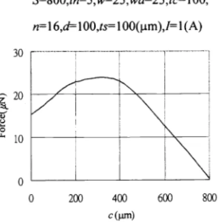
0 200 400 600 800 cQim)Fig.6.The magnetic force as a function ofthe Fig. 7. The magnetic force as a function of the
distance between the coils and the magnetic length ofthe core material block
Another parameter need to be observed is the size of core c located at the center of the planar coil. In
the present simulation, we assume that the length of the magnetic material block s is equal to 800.tm
and the thickness of coil Ic is equal to 10O.tm. As illustrated in Fig. 7, the force is gradually increased
as the length of core reached the maximum value at 380tm. The force dramatically decreases as the
length of the core keep on increasing until it reaches 80O.tm. The phenomenon demonstrates that the size of the core has great influence on the generated magnetic force. In Fig. 7, the actuator has the most
efficient combination when the length of the core is half of that of the magnetic material block. Although not report here when we change the thickness of the core ts from 100pm to I 50.tm, the
magnetic force will increased to 48.66.tN. The is due to reason that the distance between the magnetic
material block and the core is shorter than previous design. From fabrication point of view, the thickness of the coils may be restricted, while the thickness of the core can be increased without any
difficulty.
The final important parameter that we need to discuss is the cross section of the coils. As we know,
the magnetic force is proportion to the square of the electrical current. This means that the magnetic
force increases as the electrical current increases. However, one of the major problems in designing the cross section of the coils is the electrical current existed in the coils. Higher electrical current produces
higher temperature that may causes the coils to be burned down. The solution is to increase the cross
section ofthe coils since the larger cross section can sustain higher electrical current. However, in order
to increase the cross section, we must add the thickness and width of the coils. Since the width of the
coils will decrease the number of the coils n and reduce the force (as we mentioned in Fig. 4). Thus, the
best alternative is to increase the thickness of the coils in order to improve the force. This is the main
reason that we design the coils with high thickness and high aspect ratio.
S800,tn'5,w'25,wd25,tc25,
nl2,ts25(.tm),Il(A)
60z 40
a
20 0 S800,tn'5,w25,wd25,tc1OO, n1 6,dlOO,tslOO(l.Lm),11(A)Iv. Fabrication Technology and Experimental Results
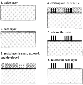
In Fig 8, a schematic processing sequence for the fabrication of the coils or the magnetic block is given. A thermal oxide is grown on the silicon wafer that is acted as an insulating layer. A 200nm Cu seed layer for the electroplating is sputtered after a lOOnm adhesive Cr layer has been deposited. A thick AZ 4620 resist layer (approximately 34km) is spun, exposed, and developed. Then a Cu or NiFe layer is electroplated on the given pattern. Finally, the resist layer is stripped and the Cu seed layeris etched. Note that for the purpose of forcing the coils to form an electrical circuit, we added two
processing layers on the Cu seed layer. One is a lOtm Cu layer and the other is a lOj.tm Su8 insulating
layer with contact holes. The finished pattern and the coils are exhibited on Fig. 9 and Fig. 10, respectively. The coils is 25tm in width, 34irn in thickness and 2(e) in electrical resistance.
On the top of the developed structure, we use the polyimide material to make the defomable
structure. First, a l0tm polyimide layer is spun on a silicon wafer. By using the same electroplating
1. oxide layer 4. electroplate Cu or NiFe
r
1iii wI
2.seed layer
: • : : : •
5
releasethe resist
:111
3.resist layer is spun, exposed, •
:
and developed
6. release the seed layer
_____________________
nj
Fig.8. A schematic processing sequence for the fabrication of the
AZ 4620 material
/
/
8001 10K
Fig. 10.Theplanarcoils
process as described previously, NiFe block is deposited on the polyimide layer. Silicon is etched at the
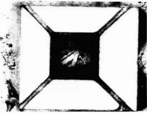
backside using KOH. The result is shown in Fig. 11. Finally, we use the excimer laser to dice the polyimide layer which enable us to make the pattern. The finished structure with a NiFe block
supported by four beams is shown in Fig.12. Here, the square NiFe block is 8OOim in length and IOMm
in thickness. Also the length and the width of the beam are 10OO.tm and 2O.tm, respectively.
Consequently, we perform the finite element simulation to calculate the stiffness of the structure by assuming the young's modulus of the polyimide material is 7.O(GPa). The resulting stiffness of the structure is 1.92 j.im/aN.
Upon the manufacturing process and simulation has been completed, we performed a series of experimental tests on the electromagnetic microactuator. Firstly, in order to measure the curvature or
Fig. 11.Electroplating the NiFe block on the polyimide layer
Fig. 12. The structure processing by excimer laser become a NiFe block supported by four beams
the deflection of the polyimide under the effect of magnetic material block. A laser interfering
instrument is used and the vertical deflection of the polyimide structure is about 1001am. From the
device has been mounted, the measured distance between the coils and the magnetic block is about 1 OOtm. The magnetic material block on the deformable structure has a 4tm deflection at the current 0.5(A). At about 1 .0(A) the coils burned down due to the high temperature. Thus we conclude that if we can shorten the mounted distance between magnetic material block and coils, more deflection can
be generated. Note that the force obtained from previous calculated stiffness is 7.68tN if the deflection is 4 tm. This result matched well with the numerical simulation given in Fig. 7 at the current 0.5(A).
V. Conclusions
Numerical simulation results from a series ofDOE have indicated that the dimension ofcore and the
magnetic material block have great influence on planar electromagnetic actuators. When the length of
the magnetic components is equal to that of outer diameter of coil circuit, we obtain the best efficiency
in magnetic force. Furthermore, when we increase the thickness of the magnetic materials block or shorten the distance between the coils and magnetic material block, the magnetic force will increase dramatically. Furthermore, we can achieve a great magnetic force when the combination ratio of the length of the core is half of the magnetic material block. Simulation results have shown that electromagnetic actuators with high aspect ratio planar coil could sustain higher electrical current that
consequently increases the magnetic force. During the realistic fabrication, we use thick resist pattering
and electroplating technologies to increase the efficiency and performance of the electromagnetic actuator. Finally, experimental results verified the usefulness of the guidelines obtained from
simulations.
VI. Acknowledgments
The work was supported by Mechanical Industry Research Laboratories, ITRI (The Nano Engineering and Facility Technology Project). The authors would also like to acknowledge Mr. C. T.
Pang, Mr. Y. S. Lin, and Mr. M. K. Wei for helping with the polyimide layer and excimer laser.
VII. References
1. 1. J. Busch-Vishniac, "The Case for Magnetically Driven Microactuators", Sensors and Actuators
A, 33 (1992) 207-220.
2. J. Behrens, A. Mexkes, M Gebhard, W. Benecke, "Electromagnetic Actuation for Micropump and Valves", Actuator 96, 5thInternational Conference on New Actuators, 26-28 June 1996, Bremen, Germany.
3. A. Meckes, J. Behrens, W. Benecke, "A Microvalve with Electromagnetic Actuator", Actuator 98,
4. Jiroshi Hosaka, Hiroki Kuwano and Keiichi Yanagisawa, "Electromagnetic Microrelays: Concepts
and Fundamental Characteristics", Sensors and Actuators A, 40 (1994) 41-47.
5. William P. Tayler, Member, IEEE, Oliver Brand, and Mark G. Allen, Member, IEEE, "Fully Integrated Magnetically Actuated Micromachined Relays", Journal of Microelectromechamical Systems, v40,n2,June 1998,181-191.
6. M. Klopzig, "A Novel Linear Micromachined Electromagnetic Actuator Including Magnetic Suspension", Actuator 98, 6th International Conference on New Actuators, 17-19 June 1998,
Bremen, Germany.
7. D. De Bruyker, J.B. Chevrier, K. Baert, R. Puers, H. Lowe, "A Silicon Micromachined Magnetic
Actuator Using a Two Layer Electroplating Process", Actuator 96, 5thInternational Conference on New Actuators, 26-28 June 1996, Bremen, Germany.
8. Jitoshi Ota, Takuji Oda, Minoru Kobayashi, "Development of Coil Winding Process for Redial
Gap Type Electromagnetic Micro-Rotating Machine", Central Research Lab., Mithubishi Electric Corp.
9. JackW. Judy, Richard S. Muller, "Magnetic Microactuation of Torsional Polysilicon Structures", Sensors and Actuators A, 53(1996)392-397.
10.A. Feustel, 0. Krusemark, J. Muller, "Numerical Simulation and Optimization of Planar