JOURNAL OF DISPLAY TECHNOLOGY, VOL. 10, NO. 12, DECEMBER 2014 987
Display Technology Letters
Quantum Dots Enhanced Liquid Displays
Zhenyue Luo, Su Xu, Yating Gao, Yun-Han Lee, Yifan Liu, and Shin-Tson Wu, Fellow, IEEE
Abstract—Two types of dielectrophoretic liquid displays with
patterned quantum dots (QDs) array for enhancing the color performance are demonstrated. QDs not only provide vivid color ( 136% AdobeRGB in CIE1976 color space) but also greatly improve light efficiency by reducing the optical loss from color filters. These polarizer-free liquid displays offer vivid colors, high transmittance, wide viewing angle, and modest response time and contrast ratio. They are promising candidates for E-book and mobile display applications.
Index Terms—Color display, dielectrophoretic force, quantum
dot (QD), voltage-stretchable LC droplet.
I. INTRODUCTION
T
HE image quality of advanced liquid crystal displays (LCDs) and organic light emitting diode (OLED) displays has reached satisfactory level. However, power consumption, color saturation, and sunlight readability still need improve-ment. Recently, a new display based on reconfigurable liquid offers some attractive features: no need for polarizer, low power consumption, and good sunlight readability. This technology could supplement LCD and OLED in some applications where power consumption is a major concern. Several operating principles of liquid displays have been explored, such as electrophoretic [1], electrowetting [2]–[4], dielectrophoresis [5]–[7], electrofluidic [8], etc. However, these liquid displays have limited color performance. Some devices use dye-doped liquid or color filter array to generate colors [2], [7], [8]. Both dyes and color filters have a fairly broad absorption/transmis-sion band, and therefore the display device has a limited color gamut. Moreover, these approaches are not energy efficient be-cause only a portion of the backlight can pass through the dyes or color filters. To broaden the application of liquid displays, there is urgent need to enhance the color performance while keeping high optical efficiency.Recently, quantum dot (QD) is emerging as a color down-conversion material [9]–[13]. QDs are semiconductor nanocrystals with diameter of 3 10 nm. QDs absorb short
Manuscript received August 14, 2014; revised September 23, 2014; accepted September 25, 2014. Date of publication October 08, 2014; date of current ver-sion November 10, 2014.
Z. Luo, S. Xu, Y. Gao, Y. Liu, and S.-T. Wu are with the College of Optics and Photonics, University of Central Florida, Orlando, FL 32816 USA (e-mail: [email protected]; [email protected]).
Y.-H. Lee is with the College of Photonics, National Chiao Tung University, Tainan 71150, Taiwan.
Color versions of one or more of the figures are available online at http:// ieeexplore.ieee.org.
Digital Object Identifier 10.1109/JDT.2014.2360627
Fig. 1. (a) Color display based on reconfigurable LC droplet and QD t back-light. The solid red/green dots represent the red/green QDs, while the open blue dots represent the scattering particles. (b) Side-view of the cell structure at voltage-off state; (c) black state at voltage-on state; and (d) layout of the bottom substrate. The dimension of the hole and ITO stripes are not drawn to scale.
wavelength light and reemit longer wavelength and narrow-band light. This new material has high quantum efficiency, broad absorption band, and narrow emission linewidth. More amazingly, its peak emission wavelength can be tailored by controlling the QD size/composition during synthesis process. Therefore, one can design the emission spectrum to get superb color rendering property and high light efficacy. QDs have already demonstrated great advantages in general lighting and LCD backlighting.
In this letter, we used patterned QDs array to enhance the color performance of a liquid display. QDs provide outstanding color gamut (136% AdobeRGB in CIE1976 color space) and greatly reduced optical loss within each color filter by pre- con-verting the light to desired colors. We demonstrated two liquid display devices based on dielectrophoretic (DEP) force: one with voltage stretchable droplet, and the other with variable circular iris. Their optical performance is evaluated and com-pared. Overall speaking, both QD-enhanced liquid display de-vices offer low power consumption, wide viewing angle, accept-able response time and contrast ratio, and vivid colors. They are promising candidates for E-books or mobile displays.
II. LIQUID DISPLAY BASED ON VOLTAGE
STRETCHABLEDROPLET
Fig. 1(a) shows the siview structure of our proposed de-vice. It consists of blue LED, light guide plate (LGP), color down- conversion layer, light shutter array, and color filter array. In the color conversion layer, the closed circles represent the patterned green/red QDs while the open circles represent scat-tering particles. The blue LED light propagating in the LGP is steered upward. When it passes through the color conversion layer, some light is absorbed by the embedded QDs, which is in
1551-319X © 2014 IEEE. Personal use is permitted, but republication/redistribution requires IEEE permission. See http://www.ieee.org/publications_standards/publications/rights/index.html for more information.
988 JOURNAL OF DISPLAY TECHNOLOGY, VOL. 10, NO. 12, DECEMBER 2014
turn converted to green and red lights, respectively. The scat-tering particles in the blue pixels diffuse the blue light in order to balance the light distribution of each color. The light shutter array modulates the transmittance of each color pixel. Finally, the color filter array blocks the unabsorbed blue light in the green/red pixels. Since most of the light is already converted into the proper color, the absorption loss in the color filters is negligible.
Fig. 1(b) and 1(c) shows the light modulation mechanism of a single color pixel. The droplet (L1) and the surrounding liquid (L2) are sealed between two glass substrates. The bottom sub-strate is first coated with interdigitated-stripe indium–tin–oxide (ITO) electrodes with 10 m width and 10- m gap, and then coated with a hole-patterned Teflon layer. These holes are used to pin down the droplet positions [Fig. 1(d)]. In the voltage-off state, the droplets shrink with the smallest surface-to-volume ratio and rest in the holes. Thus, the incident light can pass through with a large aperture. This is the white state. As the voltage increases, the droplet is stretched across the aperture, resulting in a gradually decreased transmittance. As the black droplet fills the entire aperture, dark state is achieved.
In experiment, we chose Merck LC mixture ZLI-4389 as L1. Its properties are listed as follows: dielectric constant
and , surface tension mN/m, average refrac-tive index , and density g/m . L1 is doped with 1.7% black dye S428 (Mitsui, Japan) in order to function as a light shutter. L2 is silicone oil ( , mN/m, , and g/cm ). These two liquids are immiscible with each other and match well in density. When applying a voltage on the bottom electrodes, a nonuniform lateral electric field is gener-ated across the ITO stripes. This fringing field reorients the LC molecules on the droplet border. As a result, the dielectric con-stant of the LC on the border is close to , which is much larger than that of the silicone oil . Under such circum-stance, a DEP force is generated on the dielectric liquid-liquid interface:
(1) where , , and represent the permittivity of free space, L1, and L2, respectively, and denotes the electric field on the curved droplet. This dielectric force is exerted on the liquid interface to deform the interface profile. The LC droplet is stretched along the stripe electrodes and partially blocks the incident light, resulting in a grayscale. If the droplet is further stretched to totally block the incident light, a black state is achieved, as shown in Fig. 1(c). After removing the voltage, the droplet will quickly return to its initial state due to interfacial tension.
The selection of liquid droplet material is critical to the dis-play device’s performance. The material should have high di-electric constant for low driving voltage, and low surface ten-sion for fast response time. ZLI-4389 satisfies both requirements and is a good candidate for droplet material.
Fig. 2 shows the voltage-dependent transmittance (VT) curve of a single pixel device; the insets show the droplet deformation under different voltages. At , the droplet shrinks to a small area with diameter 180 m. The pixel has a reasonably high transmittance ( 86%). As voltage increases, the droplet is
Fig. 2. Measured VT curve of the device shown in Fig. 1. The insets show the microscopic photos of a single pixel under different voltages.
Fig. 3. Single color pixel with red, green and yellow QDs at: (a)–(c) voltage-off state and (d)–(f) voltage-on state.
stretched along the stripe electrodes. At 40 , the LC droplet covers 50% of the pixel. At 50 , the droplet is stretched by 4 and it covers the whole pixel area. The contrast between bright state and dark state is about 100:1. The liquid droplet can be stretched further by a higher voltage, but in this case two un-desired phenomena could happen: (1) the dyes in LC droplet could be spread too thin to effectively absorb the incident light, resulting in a lower contrast ratio, and (2) an over-stretched droplet may not return to its original state due to increased fric-tion between the droplet and the surrounding liquid, which in turn causes hysteresis. To lower the operation voltage, we could either reduce the electrode width and gap, droplet size, or in-crease the dielectric anisotropy of the employed LC.
Fig. 3 shows the color pixels enhanced with patterned QD. The QD suspensions are purchased from Cytodiagnostics. This nanomaterial has core-shell structure, with CdS Se as core and ZnS as shell. The particle size is between 5.5 nm and 6.5 nm. The QD samples can emit color from green to red by varying the composition ratio of the core material. To demonstrate the variety of QD emission spectra, we made color pixels with red, green and yellow QDs, respectively. At , the droplets rest in holes and the pixels display brilliant colors [Fig. 3(a), (b), and (c)]. As the voltage increases to 50 V, the liquid fully blocks the light path and results in a dark state Figs. 3(d), (e), and (f)].
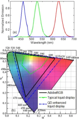
Fig. 4(a) depicts the normalized light emission spectrum from blue, green and red pixels. The emitted light has high color pu-rity with full width at half maximum nm. Fig. 4(b) is a plot of the color primaries in the CIE 1976 color
LUO et al.: QUANTUM DOTS ENHANCED LIQUID DISPLAYS 989
Fig. 4. (a) Normalized emission spectra of blue LED and yellow and red QDs. (b) Color primaries in the CIE 1976 color space.
Fig. 5. Dynamic response of a single pixel.
space. For comparison, we also include the color primary of a typical liquid display with color dyes (green dashed lines) [2]. It only covers 35.3% AdobeRGB, which means it has a very limited color reproduction capability. The blue dash–dot lines show the color primaries of QD-enhanced liquid display. Its color gamut is 136% AdobeRGB, which is even wider than that of a typical LCD (70% 80%) and OLED (100% 110%).
The response time of our liquid display depends on the droplet’s size and traveling distance. As Fig. 5 shows, for an 180 m diameter size droplet, with 60 the measured ex-panding and recovering time is 84.5 and 116 ms, respectively. The estimated travelling speed is 6.4 mm/s and 4.6 mm/s. The typical sub-pixel size of LCD is 80- m 240- m. If we can reduce the droplet size to 80 m and stretch 3 , then the estimated expanding and recovering time would be 25 ms and 35 ms, respectively. Although this response time is still insufficient for video rate operation, it is acceptable for E-book applications. If the liquid droplet size is further decreased, the droplet volume and pixel size are also reduced in proportion
Fig. 6. A single color pixel with green QD at (a) voltage-off state and (b) voltage-on state.
Fig. 7. Measured VT curve of the device shown in Fig. 6. Insets show the photographs of a single pixel under different voltages.
to the cube and square of the droplet size, respectively. Thus, the liquid may not be able to cover the entire pixel area leading to a lower contrast ratio. Fortunately, this problem can be compensated by increasing the dye concentration.
III. LIQUIDDISPLAYBASED ONVARIABLECIRCULARIRIS
To obtain faster response time, we fabricated another liquid display following the procedure reported in [5]. The structure of the liquid display device is shown in Fig. 6. We first mixed NOA65 (Norland Optical Adhesive 65, mN/m) with 2% Sudan black dye and made a polymer film by spin coating. The polymer film was exposed by UV light through a photomask, and then rinsed off with ethanol to generate a hole-pattern. We then peeled off the film and tightly stacked it onto another glass substrate, which was already coated with ITO electrode and a thin Teflon layer. The hole-pattern film acts as the polymer wall in each pixels and pinning down the liquid droplet at voltage-off state. The liquid droplet used in this experiment is the same as that reported in Section II, i.e., LC mixture ZLI-4389 with 1.7% black dye S428.
Fig. 7 shows the measured VT curve of a single pixel device, while the insets show the droplet deformations under different voltages. At , the filled LC droplet concentrated as a ring along the polymer wall due to the de-wetting properties of Teflon on the substrate. These LC droplets occupy 23% of the aperture so the pixel’s transmittance is 77%. After applying a voltage, fringing field is generated across the ITO stripes, and the generated DEP force deforms the LC droplet. Because of
990 JOURNAL OF DISPLAY TECHNOLOGY, VOL. 10, NO. 12, DECEMBER 2014
Fig. 8. Single color pixel with red, green and yellow QDs at (a) voltage-off state and (b) voltage-on state .
Fig. 9. Dynamic response of a single pixel.
the large contact area between the LC droplet and the polymer, the required voltage should be larger than a threshold value in order to overcome the friction and stretch the LC droplets. At 70 , almost half of the pixel aperture is covered by the black LC droplet. The induced aperture is not circular because the electrode is one dimensional and dielectric force exerted on the LC ring is asymmetrical. At , LC droplet covers most of the aperture and the transmittance is 3%. The contrast ratio between the bright and dark states is 25.7:1. The contrast ratio can be enhanced by increasing the concentration of black dye. However, this may affect the driving voltage and response time. Fig. 8 shows the color pixels with red, green and yellow QDs. These pixels exhibit vivid colors in the voltage-off state, and appear reasonably dark in the voltage-on state.
In this ring-shape device configuration, the liquid droplet is stretched along all the directions so that its required travel dis-tance is shorter to fully cover the pixel. Thus, the display device has a much faster response time. Fig. 9 shows dynamic response of a single pixel. With 60 , the stretching and recovering time is 11.7 ms and 14.8 ms, respectively. Such a fast re-sponse time is attractive for mobile display applications.
IV. CONCLUSION
We have experimentally demonstrated two types of QD- en-hanced dielectrophoretic liquid displays. The first type liquid display works by stretching the LC droplet. It has a relatively low driving voltage and good contrast ratio (100:1), but its re-sponse time is relatively slow. The second type liquid display
is based on variable iris. It has faster response time, but needs a higher driving voltage. We could select different displays for different applications.
Two common features of these DEP-based liquid displays are wide color gamut and high transmittance. The former enriches the color reproducibility, while the latter enhances the sunlight readability. Patterned QD has already been widely used in LEDs based on transplanting technique [14]. This structure can also be readily integrated into our liquid display devices.
Sunlight readability, which depends on the relative value of surface reflection and display brightness, is highly desirable for mobile displays and E-books. Our proposed liquid displays do not require any polarizer so that its transmittance is high and viewing angle is wide. Thus, these devices appear brighter and more vivid under the same backlight power. Moreover, recently green/red QDs with separated excitation and emission spectra have been reported [15]. With proper color filter design, we can minimize the ambient light effect and achieve a decent ambient contrast ratio.
Overall, QD-enhanced DEP liquid displays manifest several attractive features: vivid colors, high transmittance, wide view, and modest response time and contrast ratio. They are promising candidates for E-books and mobile displays.
REFERENCES
[1] B. Comiskey, J. D. Albert, H. Yoshizawa, and J. Jacobson, “An elec-trophoretic ink for all-printed reflective electronic displays,” Nature, vol. 394, no. 6690, pp. 253–255, 1998.
[2] K. Blankenbach, A. Schmoll, A. Bitman, F. Bartels, and D. Jerosch, “Novel highly reflective and bistable electrowetting displays,” J. Soc.
Inf. Display, vol. 16, no. 2, pp. 237–244, 2008.
[3] L. Li, C. Liu, H. Ren, and Q. H. Wang, “Adaptive liquid iris based on electrowetting,” Opt. Lett., vol. 38, no. 13, pp. 2336–2338, 2013. [4] C. U. Murade, J. M. Oh, D. van den Ende, and F. Mugele,
“Electrowet-ting driven optical switch and tunable aperture,” Opt. Express, vol. 19, no. 16, pp. 15525–15531, 2011.
[5] H. Ren, S. Xu, and S. T. Wu, “Optical switch based on variable aper-ture,” Opt. Lett., vol. 37, no. 9, pp. 1421–1423, 2012.
[6] H. Ren, S. Xu, and S. T. Wu, “Voltage-expandable liquid crystal sur-face,” Lab on a Chip, vol. 11, no. 20, pp. 3426–3430, 2011. [7] S. Xu, H. Ren, Y. F. Liu, and S. T. Wu, “Color displays based on
voltage-stretchable liquid crystal droplet,” J. Display Technol., vol. 8, no. 6, pp. 336–340, Jun. 2012.
[8] J. Heikenfeld, K. Zhou, E. Kreit, B. Raj, S. Yang, B. Sun, A. Mi-larcik, L. Clapp, and R. Schwartz, “Electrofluidic displays using young-laplace transposition of brilliant pigment dispersions,” Nat.
Photon., vol. 3, no. 5, pp. 292–296, 2009.
[9] S. Coe-Sullivan, “Quantum dot developments,” Nat. Photonics, vol. 3, no. 6, pp. 315–316, 2009.
[10] Z. Luo, Y. Chen, and S.-T. Wu, “Wide color gamut LCD with a quantum dot backlight,” Opt. Express, vol. 21, no. 22, pp. 26269–26284, 2013.
[11] S. Coe-Sullivan, W. Liu, P. Allen, and J. S. Steckel, “Quantum dots for LED downconversion in display applications,” ECS J. Solid State Sci.
Technol., vol. 2, no. 2, pp. R3026–R3030, 2013.
[12] Z. Luo, D. Xu, and S. T. Wu, “Emerging quantum-dots-enhanced LCDs,” J. Display Technol., vol. 10, no. 7, pp. 526–539, Jul. 2014. [13] Z. Luo and S. T. Wu, “A spatiotemporal four-primary color LCD with
quantum dots,” J. Display Technol., vol. 10, no. 5, pp. 1–6, May 2014. [14] H. Cho, C. Lee, J. Kwak, D.-M. Shin, W. K. Bae, J. Lim, K. Char, and S. Lee, “38.4: Full-color patterning of Quantum Dot (QD) light-emitting diodes using QD transplanting techniques,” SID Dig. Tech. Papers, vol. 42, no. 1, pp. 526–528, 2011.
[15] N. P. J. Kurtin, B. Theobald, N. Stott, and J. Osinski, “Quantum dots for high color gamut LCD displays using an on-chip LED solution,”