Internet-Based Learning Platform for Power Electronics
Courses
1*
Shun-Chung Wang 2Juing-Huei Su 3Yi-Hua Liu 1Wei-Sibge Liaw 1Shou-Zhuang Lin
1
Department of Electrical Engineering, Lunghwa University of Science and Technology
2
Department of Electronic Engineering, Lunghwa University of Science and Technology
3
Department of Electrical Engineering, National Taiwan University of Science and Technology
*
Corresponding author e-mail: [email protected]
Abstract
This paper presents internet-based learning platform for power electronics courses. The aim of the proposed distance learning system is to realize a platform capable of constructing a wide range of circuit topologies and control techniques, thus enabling students to gain better understanding of power electronics converters through practical experiments. The proposed platform consists of a reconfigurable power electronics testbed, a Web-based distance laboratory and an interactive e-learning platform. The reconfigurable power electronics testbed can be configured by the student via a Web-based interface. The internet accessible distance laboratory system permits the instructors and students to remotely conduct experiments over the Internet. The integrated interactive multimedia material can assist to the educational environment of power electronics courses. The advantages of the proposed platform include flexibility, friendly user interface, provision for distance waveform measurements and removal of laboratory time and space constraint. Positive response from students indicates that the presented platform is extremely useful for power electronics courses.
Keywords: e-learning platform, software reconfigurable, distance laboratory, power electronics.
I. INTRODUCTION
As to today more than 75% of all generated power was processed by power electronics. The extensive use of switching converter circuits in electronic products and systems makes the fundamental understanding of power electronics a necessity for students of engineering institute and electrical or electronic engineers. This trend has resulted in an increased interest in providing power electronic courses at the senior undergraduate and the graduate levels in various institutions [1-3]. Teaching a power electronics course is somewhat challenging since the
field is quite broad and requires significant knowledge in multiple areas of electrical and computer engineering. These areas include of electronics, control theory, semiconductor devices, and electromagnetics. The job of the course provider is often made more difficult because theoretical analysis of topics, such as analog electronics, magnetic characteristics, and compensator design, are particularly hard to comprehend without experimental observation. Thus, an effective power electronics course should ideally contain hands-on design and experimental work in addition to the study of the theory and simulations [1-6].
On the other hand, the global connectivity of the Internet and a new generation of hardware and software applications have made e-learning emerging as one of the fastest-moving trends in higher education [7, 8]. Using new media and IT-technologies in classroom can not only make studying more attractive to the student, but also make teaching much easier. Another advantage of e-learning is the independence of working place and time. Recently, many e-learning educational systems have been developed, targeted to specific environments [9-14]. Among them, many approaches have been documented in order to improve the curriculum of power electronics offered for electrical and electronic engineering students [11-14]. These methods can be categorized into three major types: Multimedia and java technologies have been used to illustrate power electronics concepts and circuit operation as well as to help the design process in [11, 13]; Circuit simulation software has been utilized to deepen the student's comprehension of power electronics and to serve as a design tool for power converter circuits in [6, 12]; Virtual laboratory has been exploited to offer the students different levels of interaction and understanding of power electronics systems [9, 14]. However, papers dealing with the combination of theory explanation and hardware-based experiments on a Web-based platform are rarely found.
In this paper, a software reconfigurable e-learning platform for power electronics courses is presented. The advantages offered by the proposed
platform are: 1. the power electronics testbed can be configured by the student via a Web-based interface to construct a wide variety of converters and inverters, 2. the Internet accessible distance laboratory system permits the instructors and students to remotely conduct experiments over the Internet, and 3. the integrated interactive multimedia materials can assist to the educational environment of power electronics courses and can be executed on any modern personal computer without additional hardware. Therefore, the proposed e-learning platform is flexible, easy-to-use and is suitable for power electronics education.
II. SYSTEM CONFIGURATION
Fig. 1 shows the block diagram of the proposed system. From Fig. 1, the whole system can be divided into three major parts: software reconfigurable power electronics testbed, Web-based distance laboratory and user interactive e-learning platform. Brief descriptions of each part are as follows:
Fig. 1. Block diagram of the proposed system.
a. Power electronics testbed: the proposed power electronics testbed consists of a reconfigurable hardware testbed, a digital PWM generator and various types of loads. This hardware testbed includes a fully software reconfigurable processing core based on matrix switch module from National Instruments Corp. and a set of discrete power devices and passive components. The digital PWM generator is used to provide the gating signals required by power electronics converters. The proposed power electronics testbed intends to let the students designing their own converters and testing them.
b. Web-based distance laboratory: the Web-based distance laboratory contains different types of measurement equipments such as digital storage oscilloscopes (DSO) and digital multi-meters (DMM). These apparatus are remotely operated by means of GPIB or RS-232 protocols that are generated by the interface cards installed on the personal computer (PC). The proposed laboratory experiments can give practical introduction to the operation and control of power electronic switching circuits. Making the laboratory platforms available through the Internet
allows the students to revise their lab class outside lab hours, making the lab virtually accessible 24-hours a day, 7 days a week.
c. E-learning platform: the e-learning platform is implemented on a standard PC. The proposed e-learning platform composes of a Web-based course contents, the interface cards used to configure the hardware testbed and to control distance laboratory instruments, and a graphical waveform display screen. The contents of this e-learning platform contain not only lecture notes and simulations but also on-line experiment interface which will permit the students to learn in a truly interactive mode.
The physical implementation of the whole system is shown in Fig. 2; detailed descriptions about each part will be given in the following sections.
Fig. 2. Physical implementation of the proposed system.
III. SOFTWARE RECONFIGURABLE POWER ELECTRONICS TESTBED
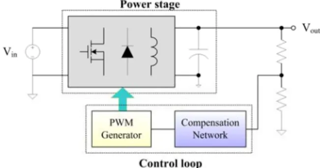
An effective power electronics course should ideally contain hands-on design and experimental work in addition to the study of the theory and simulations. Fig. 3 shows the block diagram of a typical power electronics system. From Fig. 3, the main components of a power electronics converter are the power stage, the compensation network and the pulse width modulator. The proposed power electronics testbed intends to let the students obtain better understanding of power converter circuits, and will be described in the following subsections.
Fig. 3. Block diagram of a typical power electronics system.
A. Reconfigurable hardware testbed
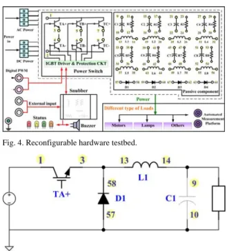
In this paper, the reconfigurable hardware testbed is used to let the students construct their own converters. From Fig. 3, the power stage of a typical power electronics converter consists of only passive components (such as inductor(s), capacitor(s)) and power devices (such as switch(es) and diode(s)). Based on this concept, a reconfigurable hardware as shown in Fig. 4 is presented. From Fig. 4, this hardware includes a range of discrete semiconductor devices and passive components, which can be used to implement any kind of basic power electronics converters and inverters through appropriate wiring of the terminals. For example, by wiring the connection as shown in Fig. 5, a buck converter can be build.
Fig. 4. Reconfigurable hardware testbed.
Fig. 5. Using the reconfigurable hardware testbed to construct a buck converter.
The only difference between the proposed testbed and the ones presented in [2], [5] or [15] is that the proposed hardware can be configured via software, this is essential for a distant learning platform. In the previous literatures, students construct converters and inverters using simple connections on a faceplate. However, in an e-learning environment, especially for Web-based learning, this can be a major problem because the students are often not present in the laboratory, therefore manually wiring is impossible. In this paper, a matrix switch module is utilized to deal with this problem. Matrix switch module can be used to connect any input to any output; therefore the overall system can easily and dynamically change the internal connection path without any external manual intervention.
B. Digital PWM generator
From Fig. 3, another fundamental issue for power electronics education is its controller (compensation circuit) design. In order to achieve this goal, students should be able to change the duty cycle
and then observe the waveforms around the major components to verify the basic operating equations. This concept can usually be found in some popular power electronics textbooks such as those ones by Mohan [16] and Erickson [17]. Consequently, a programmable PWM generator is required. Dedicated analog circuits, PWM ASICs and programmable function generators all can be used to fulfill this requirement as presented in [2], [5], [6] and [15]. However, these solutions can only realize open loop control.
Digital controllers such as μcontrollers and digital signal processors (DSP) are used to attain both open loop and close loop control objectives, as introduced in [4, 18-19]. These systems let the users control power electronics converters digitally using a rapid prototyping tool with flexibility. To simplify the design, a FPGA-based digital PWM generator has been designed to provide the switching signals to the power electronics converters. FPGA has been used in various fields to implement the digital controller of different types of applications, they allow concurrent operation, enable high performance; therefore being suitable for implementing timing diagrams and modulation strategies requiring high-speed. The block diagram of the proposed controller is shown in Fig. 6. Observing Fig. 6, the user can specify the control type (open loop or close loop) as he/she wishes. If the user chooses to perform an open loop control, he/she can then input the duty cycle (0~100 %) of the PWM signals through RS-232 interface directly, the entered value will be compared with an internally generated high frequency carrier to generate adequate PWM signals accordingly. On the other hand, if the user chooses to perform a close loop control, he/she will be requested to perform a compensator design process through the e-learning platform, and the obtained controller parameters will be digitalized using bilinear transformation and then transferred to the FPGA through RS-232 interface. The bilinear transformation can be expressed as
2 1 s z s T z 1 − = ⋅ + (1)
Where Ts is the sampling time.
Fig. 6. Block diagram of the proposed digital PWM generator.
After the controller parameters are set, the close loop digital control will then be handled by the FPGA, as shown in Fig. 6. In this way, the students can design the compensation circuit in his/her familiar
analog way without the prerequisite of digital control theory.
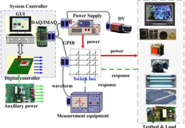
IV. DISTANCE LAB IMPLEMNETATION As shown in Fig. 7, an internet accessible distance laboratory system has been developed. From Fig. 7, the student is located on the client side and accesses the lab simply through an Internet connection using an available browser. A networked-PC server is located in the physical lab, and is GPIB interfaced to measurement instruments such as DMM and DSO. A dynamic web page, where a virtual front panel of the instruments is displayed, is also implemented in the server. The students can then read the instruments and operate the equipments using this panel if required. The control and the user interface software is developed using LabView software. The main advantage of this Web-based laboratory is that it allows employing the same equipment used in the traditional lab classes.
The dynamic web server shown in Fig. 7 makes the front panel available to all clients, so that all clients connected to the server can see and operate the front panel. Since the instruments can be used by one student at a time, a schedule is required. A booking system is introduced in the developed distant laboratory. The remote user can book an experiment for one hour and then, when the reserved time comes, the user gains a valid link to the remote lab web page.
Fig. 7. Implementation of the proposed distance laboratory.
In order to provide the students an opportunity to enhance what they have learned in the fundamental theory courses, a session of laboratory demonstration is also provided. A number of advanced power electronics applications are demonstrated in the laboratory. A corresponding webpage that describes the application will also be provided to enhance explanation and encourage questioning. By now, the demonstration laboratories include battery management circuits and electronics ballasts. This idea can easily be expanded to cover more topics on power electronics applications such as renewable energy system and motor drives.
From the description above, the proposed distance laboratory should be able to measure the currents and voltages of a variety of devices. Thus, the test points will be far more than the input
channels of DSO or DMM. Matrix switch module is again used to route signals from DSOs and DMMs to various test points on a unit under test. This concept can be illustrated in Fig. 8. Using this way, students can choose the waveforms of their interest, then measure and observe them remotely.
Fig. 8. Using matrix switch module in remote laboratory.
Using this distance laboratory, the students can conduct their experiments by accessing the lab when they most need it and from a remote location which is more comfortable for them. The distance laboratory described here directly addresses the difficulty of learning power electronics by helping students reduce the complexity to practice. From this perspective, this laboratory is of critical importance in solidifying the fundamentals of power electronics in the proposed e-learning platform.
V. POWER ELECTRONICS E-LEARNING PLATFORM
A typical power electronics curriculum should contain the theoretical lectures, the design and simulation exercise and the laboratory sessions. The theoretical lectures provide the background knowledge required for designing of power electronics converters. During the design and simulation exercise part, the students can learn to design their own basic converters according to a given design specification sheet. During the laboratory sessions, the students will be encouraged to built switching converters and/or compensation circuit according to the same design specification. After finished their design, the students are then encouraged to test them under various conditions.
In this paper, a power electronics e-learning platform is proposed. The objectives of this e-learning platform are to train the students to: 1) gain basic understanding of power electronics; 2) analyze and derive expected results; 3) simulate and verify the analysis; 4) validate through hardware experiments. In order to achieve these goals, course topics are designed carefully using a top-down approach where the fundamental concepts are included with illustrations of design examples. To
reinforce theory, all topics are tightly coupled with simulations and hardware laboratories.
1
ctrl PROP DIFF IN INT
PROP DIFF err PID IN INT
V R C R C sR C V R C s ⎡ ⎤ ⎢⎛ ⎞ ⎥ ⎢ ⎥ =⎢⎜ + ⎟+ + ⎥ ⎝ ⎠ ⎢ ⎥ ⎣ ⎦ (5) The design principle of each topic is shown in
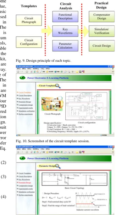
Fig. 9. From Fig. 9, each topic can be divided into three parts: templates, circuit analysis and practical design. Until recently, a number of standard topologies are provided in this platform (including buck, boost, buck-boost, Cuk, SEPIC, flyback, forward, half-bridge and full-bridge). Take the buck converter for example. The circuit photographs and circuit configurations are given at the template section, as shown in Fig. 10. The next part of the context includes circuit analysis related lectures. In this part, fundamental operation principles and key waveforms on the major component (switch(es), inductor(s), and capacitor(s)) will be introduced. Students can then try to calculate the values of some important parameters (duty cycle, inductor value, critical conduction mode boundary…etc) using basic operating equations. During this part, the proposed e-learning platform will assist the students in completing their design in a step-by-step way. The graphical user interface for parameter design is illustrated in Fig. 11. The last part of the curriculum contains a compensator design kit, a simulation tools, a distance laboratory and an on-line reconfigurable power electronics testbed. Fig. 12 shows the screenshot of the compensator design kit. In this kit, compensators for power electronics converters are introduced in the form of Web-based, interactive way. There is a guide describing step-by-step procedure of how to calculate the controller parameters. The obtained controller parameters are then tested in simulation created in MATLAB before they are digitalized and transferred to the FPGA digital PWM generator. To simplify the design process, only four predefined compensation circuits (type I~III and PID compensation circuit) are provided. The offered circuits are the most commonly used compensation techniques for power electronics converter design. Therefore, the proposed design kit is believed to suit the educational needs of an introductory power electronics course. Fig. 13 shows these error amplifier compensation circuits, and the transfer functions of each circuits can be expressed by Eq. (2)~Eq. (5).
Next, the utilization of user-friendly and powerful computer-aided simulation software tools can help students get acquainted with the dynamic behavior of the switching converter circuits and verify the correctness of their parameter design. The simulation tools used in the proposed e-learning platform is IsSpice from Intusoft Corp. An education version of IsSpice as well as examples and tutorials are provided in the presented platform. A distance laboratory as presented in Section IV is also provided, the measured waveforms for a buck converter is shown in Fig. 14.
Fig. 9. Design principle of each topic.
Fig. 10. Screenshot of the circuit template session.
1 1 1 ctrl err Type I V V =sRC (2) 2 1 2 1 2 1 1 2 1 2 1 ( ) 1 ( ) ctrl err Type II V sR C V sR C C sR C C C C + = ⎛ ⎞ + ⎜ + ⎟ + ⎝ ⎠ (3) 2 1 1 3 3 2 1 2 1 1 2 3 3 1 2 (1 )[1 ( ) ] ( )(1 ) 1 ( ) ctrl err Type III
V sR C s R R V sR C C sR C C sR C C C + + + = ⎛ ⎞ + + ⎜ + ⎟ + ⎝ ⎠ C (4)
Fig. 11. Screenshot of the parameter design session.
Fig. 12. Screenshot of the compensator design session.
Fig. 13. Typical compensation circuits power electronics circuits.
Fig. 14. Screenshot of the experimental results session.
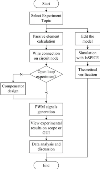
These parts of context described above are sufficient for introductory power electronics courses. For advanced learners, the proposed platform offers an on-line reconfigurable power electronics testbed, as described in Section III. For safety issues, only the experienced users are allowed to use this testbed and construct their own design. The flowchart of how to perform the on-line experiment is illustrated in Fig. 15. For increasing students' interest in power electronics, additional demonstration laboratories on some typical power electronics applications as described in Section IV is also provided. The screenshot of a battery management system is shown in Fig. 16.
The presented platform has been used for one semester by students attending a course on Power
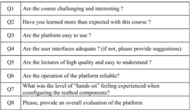
Electronics at the Department of Electrical Engineering at the Lunghwa University of Science and Technology (LHU). Such a course is at the senior undergraduate level and is optional in the student curriculum. After the course, all the students have been requested to answer (with five point scale: 1- very poor, 2-poor, 3-satisfactory, 4-good and 5-very good) an anonymous questionnaire as shown in Table 1. According to the results, the proposed platform has received a 4.5/5.0 rating, comparing with an average rating of 3.8/5.0 for electrical engineering courses at LHU. The results from the student feedback forms have been extremely positive with regard to the experiments provided in the proposed e-learning platform, the majority of students felt that such experiments enhanced their understanding of the theoretical material and made the course more interesting. The proposed platform is available on the
website http://f107b.ee.lhu.edu.tw/.
Fig. 15. Flow chart of on-line experiment.
The proposed e-learning platform is a multi-user, client-server architecture developed in the LabVIEW environment. The whole tool needs only a standard Web-browser and is independent of the operating system. It should be noted that the users should download the LabVIEW Run-Time Engine to run LabVIEW applications on computers in which the
LabVIEW development system is not installed. However, the demo version of LabVIEW Run-Time Engine is available free of charge and needs only to be installed once.
To summary, the developed platform possesses the advantages such as: hardware flexibility, friendly user interface, provision for distance waveform measurements and removal of laboratory time and space constraint.
Fig. 16. Screenshot of a battery management system.
Table 1. Questionnaire for the evaluation of the proposed e-learning platform.
VI. DISCUSSION AND CONCLUSION In this paper, a software reconfigurable e-learning platform for power electronics courses is proposed. The whole system can be divided into three major parts: software reconfigurable power electronics testbed, Web-based distance laboratory and user interactive e-learning platform. Unlike most related works, matrix switch module is used in the proposed system to realize a reconfigurable hardware testbed. This testbed together with a FPGA-based digital PWM generator form a power electronics testbed which can be configured via software, this is essential for an e-learning platform. An internet accessible distance laboratory system has also been developed; this laboratory directly addresses the difficulty of learning power electronics by helping students perform experiments on-line. Finally, an integrated e-learning platform is presented, the
graphical and multimedia nature of e-learning makes the course content more attractive to the student. Moreover, the proposed platform enables location independent learning. To summary, the developed platform boasts the advantages such as: hardware flexibility, friendly user interface, provision for distance waveform measurements and removal of laboratory time and space constraint.
There are three limitations regarding the proposed platform. Firstly, since there is no transformer in the reconfigurable hardware testbed, isolated versions of power electronics converters (such as forward and flyback converter) cannot be constructed. At present, the experiments on these converters are carried out using laboratories with prefabricated isolated converter modules. Secondly, only commonly used types of compensation circuits can be realized in the proposed digital PWM converter; however, this is acceptable for introductory courses. Lastly, the availability of the on-line experiment is limited to advanced users due to safety reasons because of the high voltages that can be generated by faulty wiring or incorrect duty cycles. This problem can be solved in two ways: First, to comply with safety rules, the equipment needs to operate from a lower input voltage, and the voltage source should equip with built-in protection functions. Next, an artificial intelligence algorithm which can be utilized to determine the correctness of the wiring should be developed; this will be investigated in the future work.
The proposed platform has been valued in general terms very positively. As seen in the survey, the students have shown a good opinion about the course. Hence, one can conclude that the experience has been positive and is worth repeating in the following years. Meanwhile, the proposed e-learning platform will be constantly improved according to the feedback from our students.
Acknowledgement
This work was sponsored by National Science Council, Taiwan, under research grant NSC 95-2516-S-262-003-MY2.
References
[1] E.A. McShane, M. Trivedi, K. Shenai, "An improved approach to application-specific power electronics education. Curriculum development," IEEE Transactions on Education, Vol. 44, No. 3, Aug. 2001, pp. 282-288.
[2] M. Trivedi, E.A. McShane, R. Vijayalakshmi, A. Mulay, S. Abedinpour, S. Atkinson, K. Shenai, "An improved approach to application-specific power electronics education-switch characterization and modeling," IEEE Transactions on Education, Vol. 45, No. 1, Feb. 2002, pp. 57-64.
[3] S.A. Shirsavar, "Teaching practical design of switch-mode power supplies," IEEE Transactions on Education, Vol. 47, No. 4, Nov. 2004, pp. 467-473.
[12] I. Chamas, M.A.E. Nokali, "Automated PSpice simulation as an effective design tool in teaching power electronics," IEEE Transactions on Education, Vol. 47, No. 3, Aug. 2004, pp. 415-421.
[4] N. Mohan, W.P. Robbins, P. Imbertson, T.M. Undeland, R.C. Panaitescu, A.K. Jain, P. Jose, T. Begalke, "Restructuring of first courses in power electronics and electric drives that integrates digital control," IEEE Transactions on Power
Electronics, Vol. 18, No. 1, Part 2, Jan. 2003, pp. 429-437. [13] J. Hamar, H. Funato, S. Ogasawara, O. Dranga, C.K. Tse, "Multimedia based e-learning tools for dynamic modeling of DC-DC converters," Conference Record of the 2005 IEEE International Conference on Industrial Technology, 14-17 Dec. 2005, pp. 17-22.
[5] J.M. Williams, J.L. Cale, N.D. Benavides, J.D. Wooldridge, A.C. Koenig, J.L. Tichenor, S.D. Pekarek, "Versatile hardware and software tools for educating students in power electronics," IEEE Transactions on Education, Vol. 47, No. 4,
Nov. 2004, pp. 436-445. [14] P. Spanik, L. Hargas, M. Hrianka, I. Kozehuba, "Application of Virtual Instrumentation LabVIEW for Power Electronic System Analysis," Conference Record of the 12th International Power Electronics and Motion Control Conference, Aug. 2006, pp. 1699-1702.
[6] L. de V.B. Machado Neto, F.M. de Souza, R.C. Figueiredo, R.C. Ivo, "Power Electronics Laboratory at PUC Minas/Brazil: simulation and experiment's tools," Conference Record of the 30th Annual Frontiers in Education Conference,
Vol. 2, 18-21 Oct. 2000, pp. S1E/1-S1E/6. [15] V.G. Agelidis, "Introducing power electronics technologies into the aerospace engineering undergraduate curriculum," Conference Record of the IEEE 35th Annual Power Electronics Specialists Conference, Vol. 4, 20-25 June 2004, pp. 2719-2724.
[7] R. Ubell, "Engineers turn to e-learning," IEEE Spectrum, Vol. 37, No. 10, Oct. 2000, pp. 59-63.
[8] R.S. Friedman, F.P. Deek, "Innovation and education in the digital age: reconciling the roles of pedagogy, technology, and the business of learning," IEEE Transactions on Engineering Management, Vol. 50, No. 4, Nov. 2003, pp. 403-412.
[16] N. Mohan, T. M. Undeland, W. P. Robbins, Power Electronics: Converters, Applications and Design, New York: Wiley, 2003.
[9] M.M. Albu, K.E. Holbert, G.T. Heydt, S.D. Grigorescu, V. Trusca, "Embedding remote experimentation in power engineering education," IEEE Transactions on Power Systems, Vol. 19, No. 1, Feb. 2004, pp. 139-143.
[17] R. W. Erickson, D. Maksimovic, Fundamentals of Power Electronics, Berlin: Springer, 2000.
[18] Z.Z. Ye, M.M. Jovanovic, "Implementation and performance evaluation of DSP-based control for constant-frequency discontinuous-conduction- mode boost PFC front end," IEEE Transactions on Industrial Electronics, Vol. 52, No. 1, Feb. 2005, pp. 98-107.
[10] O.G. Bellmunt, D.M. Miracle, S.G. Arellano, A. Sumper, A.S. Andreu, "A distance PLC programming course employing a remote laboratory based on a flexible manufacturing cell," IEEE Transactions on Education, Vol. 49, No. 2, May 2006, pp. 278-284.
[19] S. Jung, S.S. Kim, "Hardware Implementation of a Real-Time Neural Network Controller With a DSP and an FPGA for Nonlinear Systems," IEEE Transactions on Industrial Electronics, Vol. 54, No. 1, Feb. 2007, pp. 265-271. [11] U. Drofenik, J.W. Kolar, "Interactive Power Electronics
Seminar (iPES)-a web-based introductory power electronics course employing Java-applets," Conference Record of the 33rd Annual Power Electronics Specialists Conference, Vol. 2, 23-27 June 2002, pp. 443-448.