IEEE PHOTONICS TECHNOLOGY LETTERS, VOL. 9, NO. 12, DECEMBER 1997 1643
Reductions of Soliton Interactions and Timing
Jitters by Chirped Fiber Bragg Grating Filters
Sien Chi, Shy-Chaung Lin, and Jeng-Cherng Dung
Abstract— This letter numerically investigates a comparison
between soliton interaction and timing jitter effects using transmission fiber that contains: 1) the zigzag-sliding-frequency Fabry–Perot filters (ZSF FPF’s) alone and 2) both the ZSF FPF’s and chirped fiber Bragg grating filters (CFBGF’s). We have found that the latter scheme is more effective for reducing the soliton interactions and noise-induced timing jitters, because the CFBGF’s introduce a large positive second-order dispersion and plays the dual role of a filter and a dispersion compensation fiber.
Index Terms— Chirped fiber Bragg grating filter, optical
soli-tons.
I. INTRODUCTION
I
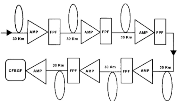
N A LONG-DISTANCE soliton communication systemthat uses optical amplifiers to compensate for the fiber loss, the major limits in the soliton transmission are the noise-induced timing jitter (Gordon–Haus effect) and the interactions between adjacent solitons. The insertion of bandpass filters after every optical amplifier can reduce the soliton interactions and timing jitter [1], [2]. If the center frequency of the filter is slowly sliding with the distance along the fiber, the reductions of the soliton interactions and timing jitter are better than those with filter of fixed center frequency [3], [4]. Furthermore, the zigzag-sliding-frequency Fabry–Perot filter (ZSF FPF) was proposed to reduce the soliton interactions and timing jitter [5]. On the other hand, dispersion management techniques using dispersion compensation fibers (DCF) are suggested to reduce the noise-induced jitter and soliton interactions [6], [7]. However, these techniques are difficult to implement for wavelength-division-multiplexing (WDM) systems, since different sections of DCF’s are needed for different channels. In this letter, we propose to use the ZSF chirped fiber Bragg grating filter (CFBGF) to reduce the soliton interactions and noise-induced timing jitter. The CFBGF plays the dual role of a filter and a DCF and it is more compact than the DCF. The CFBGF can be fabricated by UV laser and the phase mask photoimprinting technique [8]. For a WDM system, the CF-BGF’s for different wavelengths can be made in a single short length of fiber. The soliton transmission system we propose is shown as Fig. 1, after every 180 km, which corresponds to six amplifier spacings, we replace the ZSF FPF by the ZSF CFBGF periodically. By properly designing, the CFBGF
Manuscript received February 26, 1997; revised August 5, 1997. This work was supported by the National Science Council of the Republic of China under Contract NSC 85-2215-E-009-014.
The authors are with the Institute of Electro-Optical Engineering, National Chiao Tung University, Hsinchu, Taiwan 30050, R.O.C.
Publisher Item Identifier S 1041-1135(97)08495-4.
Fig. 1. Schematic diagram of the soliton transmission system by using the sliding-frequency FPF and CFBGF.
can have high positive second-order dispersion and suitable bandwidth for the soliton transmission. We numerically study the reduction of the soliton interactions and noise-induced timing jitter by the ZSF FPF and the ZSF FPF and CFBGF. It is found that the ZSF FPF and CFBGF can reduce the soliton interaction more effectively than the ZSF FPF. When we consider the soliton interaction and noise-induced timing jitter simultaneously, the transmission distance can be greatly increased by using the ZSF FPF and CFBGF.
The wave equation that describes a soliton transmission in a single-mode fiber (SMF) can be described by a modified nonlinear Schr¨odinger equation
(1)
where and is reciprocal group velocity, and
represent the second-order and third-order dispersion of the fiber, respectively, is the slowly varying amplitude, is the Kerr coefficient, is the slope of Raman gain profile, and is the fiber loss. For the numerical simulation, the coefficients
in (1) are taken as 0.255 ps /km, 0.075 ps /km,
3.2 10 m /w, 3.8 10 (ps m)/W, and
0.22 dB/km.
The reflectivity of a CFBGF can be calculated from the coupled-mode equations [9]
(2a) (2b)
1644 IEEE PHOTONICS TECHNOLOGY LETTERS, VOL. 9, NO. 12, DECEMBER 1997
(a) (b)
Fig. 2. Second-order dispersion for two different optical filters: (a) the FPF and (b) the CFBGF.
where and are the amplitude of the forward and
backward propagating modes along the direction. is the coupling coefficient and varies along the grating as
(3) where is the maximum coupling coefficient at 0 and is length of the grating, represents the phase mismatch of the grating and is given by
(4)
where is the propagation constant and is the
propagation constant of central wavelength,
is grating period at 0, is the central wavelength
of carrier waves and is the mode index, and are
the chirped coefficients. If is set to be zero, the CFBGF is linearly chirped. This linear CFBGF will induce positive third-order dispersion. This positive third-order dispersion will increase the third-order dispersion of the transmission system and distort the soliton pulse shape. We can adjust the to decrease the third-order dispersion of the CFBGF and then the third-order dispersion of the fiber link can be reduced. The parameters of chirped fiber Bragg grating filters are chosen as
50 , 251.33, 816, 26 mm. The
transfer function of the Fabry–Perot is given as
(5)
where is the filter bandwidth, and is the
initial soliton carrier frequency, and is the
center frequency of the filter. The center frequency of the ZSF filter is up-sliding first and then down-sliding along the fiber.
(a)
(b)
Fig. 3. Power evolutions of soliton bit stream along the fiber by using two different optical filters: (a) the ZSF FPF and (b) the ZSF FPF and CFBGF. The data were recorded every 690 km.
For the fixed center frequency FPF, we simulate the single soliton transmission with different filter bandwidths which range from 150 to 700 GHz, and find that the bandwidths which can maintain minimum pulsewidth variation range from 500 to 550 GHz. The critical sliding rate and optimum zigzag-sliding period have been proposed [5], [10]. We simulate the different combination of the bandwidth, sliding rate and zigzag-period for the FPF. It is found that the optimum combination of the bandwidth, sliding rate and zigzag-period for the ZSF FPF are 540 GHz, 11 GHz/Mm, and 11 Mm, respectively. In the zigzag-sliding frequency FPF and CFBGF case, the sliding rate and zigzag-period are 11 GHz/Mm and 10 Mm, respectively.
Fig. 2 shows the second-order dispersion of filters for the Fabry–Perot filter and the CFBGF. It is seen that, at the central
CHI et al.: REDUCTIONS OF SOLITON INTERACTIONS AND TIMING JITTERS 1645
Fig. 4. Power evolution of single soliton along the fiber by using the ZSF FPF and CFBGF. It is noted that the temporal shift which are due to the first-order dispersion of filters have been removed.
frequency of the filters, the second-order dispersions are 0 ps , 32 ps for the Fabry–Perot filter, and the CFBGF, respectively. The high positive second-order dispersion of the CFBGF will compensate the negative dispersion of the transmission fiber and reduce the noise-induced timing jitter and the soliton interactions. Fig. 3 shows the evolutions of soliton bit stream (0 100 110 111 011 110) by using the ZSF FPF and the ZSF FPF and CFBGF, when the noise is not considered. The considered initial soliton pulsewidth is 7 ps, the amplifier spacing is 30 km, and the initial soliton separation is 4 pulsewidth separation (35.7 Gb/s). One can see that the soliton interaction depends on the bit pattern. In Fig. 3(a), for the case of ZSF FPF, the solitons with bit pattern (0110) attract each other, then separate afterwards. The minimum pulse separation occurs approximately at 1.44 Mm. In Fig. 3(b), for the case of ZSF FPF and CFBGF, one can see that the soliton shape undergoes significant variation but the soliton separations are well maintained over 11 Mm. Therefore, the soliton interactions can be significantly reduced by the ZSF FPF and CFBGF. In Fig. 3, the pulse waveforms swing in a different way in each case because different filters introduce different frequency-dependent phases to solitons and change their group velocities. Fig. 4 shows the power evolution of single soliton transmission by using the ZSF FPF and CFBGF, where the pulse shape undergoes significant variations during every 180-km period. It is noted that, in Fig. 4, the temporal shift which is due to the first-order dispersion of the filters has been removed.
For a soliton transmission system with a 7-ps pulsewidth and a 4.0-pulsewidth separation, a 10 bit-error rate (BER) corre-sponds to a 1.53-ps standard deviation of the timing jitter [11]. Fig. 5 shows the standard deviation of the timing jitter of the solitons caused by the combination of the soliton interactions and ASE noise-induced timing jitter for the 512 pseudorandom bits. In Fig. 5, the allowed transmission distances for a 10
Fig. 5. Evolutions of the standard deviation of the timing jitters. (?): ZSF FPF, (1): ZSF FPF and CFBGF.
BER are 1.17 Mm, beyond 11 Mm for the ZSF FPF, the ZSF FPF and CFBGF, respectively.
II. CONCLUSION
We have numerically studied the optical soliton transmission systems by using the ZSF FPF alone and both the ZSF FPF and CFBGF. It has been shown that the ZSF CFBGF’s in an optical soliton transmission system are effective devices for reducing the soliton interactions and ASE noise-induced timing jitter because the ZSF CFBGF introduces large positive second-order dispersion.
REFERENCES
[1] Y. Kodama and A. Hasegawa, “Generation of asymptotically stable optical solitons and suppression of the Gordon–Haus effect,” Opt. Lett., vol. 17, no. 1, pp. 31–33, 1992.
[2] A. Mecozzi, J. D. Moores, H. A. Haus, and Y. Lai, “Soliton transmission control,” Opt. Lett., vol. 16, no. 23, pp. 1841–1843, 1991.
[3] Y. Kodama and S. Wabnitz, “Reduction and suppression of soliton inter-actions by bandpass filters,” Opt. Lett., vol. 18, no. 16, pp. 1311–1313, 1993.
[4] L. F. Mollenauer, J. P. Gordon, and S. G. Evangelides, “The sliding-frequency guiding filter: An improved form of soliton jitter control,”
Opt. Lett., vol. 17, no. 22, pp. 1575–1578, 1992.
[5] J. C. Dung, S. Chi, and S. Wen, “Reduction of soliton interactions by zigzag sliding frequency guiding filters,” Opt. Lett., vol. 20, no. 18, pp. 1862–1865, 1995.
[6] W. Forysiak, K. J. Blow, and N. J. Doran, “Reduction of Gordon–Haus jitter by post-transmission dispersion compensation,” Electron. Lett., vol. 29, no. 23, pp. 1225–1226, 1993.
[7] M. Suzuki, I. Morita, N. Edagawa, S. Yamamoto, H. Taga, and S. Akiba, “Reduction of Gordon–Haus timing jitter by periodic dispersion compensation in soliton transmission,” Electron. Lett., vol. 31, no. 23, pp. 2027–2029, 1995.
[8] K. O. Hill, F. Bilodeau, B. Malo, T. Kitagawa, S. Theriault, D. C. John-son, and J. Albert, “Chirped in-fiber Bragg gratings for compensation of optical-fiber dispersion,” Opt. Lett., vol. 19, no. 17, pp. 1314–1316, 1994.
[9] M. Matsuhara, J. Opt. Soc. Amer., vol. 65, no. 7, pp. 804–813, 1975. [10] A. Mecozzi, M. Midrio, and M. Romagnoli, “Timing jitter in soliton
transmission with sliding filters,” Opt. Lett., vol. 21, no. 6, pp. 402–404, 1996.
[11] A. Mecozzi, “Long-distance soliton transmission with filtering,” J. Opt.