國立交通大學
光電工程研究所
碩士學位論文
利用反向脈衝光時鐘注入半導體光放大
器進行非歸零/歸零格式之轉換研究
Dark-optical-comb Injected Semiconductor
Optical Amplifier for All-optical
Non-return-to-zero to Return-to-zero Data
Format Conversion
研究生:游昆潔
指導教授:林恭如 教授
郭浩中 教授
摘 要
論文名稱:利用反向脈衝光時鐘注入半導體光放大器進行非歸零/歸零格式之轉 換研究 校所別:國立交通大學光電工程研究所 頁數:1 頁 畢業時間:九十五學年度第二學期 學位:碩士 研究生:游昆潔 指導教授:林恭如 老師 郭浩中 老師 關鍵詞:半導體光放大器、交叉增益調變、反向脈衝光時鐘、全光格式轉換、 啾嚬 在本論文中,我們使用 10 GHz 的反向脈衝光時鐘訊號背向注入半導體光 放大器,實現OC-192 下全光之非歸零碼轉歸零碼的格式轉換。以消光比為 7.13 dB 非歸零碼資料訊號外部注入,在不需要放大的情況之下,經過半導體光放 大器格式轉換器轉換後,歸零碼資料訊號的消光比可提升到 13.6 dB。而在位 元率10 Gbit/s 的操作下,轉換後歸零碼訊號的接收功率在-18.3 dBm 時,仍可 以獲得小於 10-12的誤碼率,獲得功率補償為-3.7 dB 的改善。另外,我們也利 用多波長及單波長的反向脈衝光時鐘訊號分別注入半導體光放大器,進行轉換 後歸零碼訊號的啾頻研究;理論分析顯示多波長的反向脈衝光時鐘訊號注入, 不僅能在時域上縮短半導體光放大器中的增益窗口,更可以在頻域上有效地窄 化其增益線寬,進而降低轉換後訊號的啾嚬。實驗結果顯示在高位元率的操作 下,必須提高半導體光放大的電流及增加反向脈衝光時鐘訊號注入功率。經由 多 波 長 注 入 轉 換 後 的 訊 號 之 啾 嚬 可 以 比 單 波 長 注 入 的 結 果 還 要 明 顯 降 低 2.1GHz (約為 16 %),然而脈衝寬也相對地加寬 1 ps (劣化度 3 %)。我們提出的 反向脈衝光時鐘訊號注入半導體光放大器實現全光非歸零碼轉歸零碼的格式 轉換器,具有簡單的架構,而且轉換後的歸零碼訊號其波長與資料極性皆與輸 入的非歸零碼訊號一致。ABSTRACT
Title:Dark-optical-comb Injected Semiconductor Optical Amplifier for All-optical Non-return-to-zero to Return-to-zero Data Format Conversion
Pages:1 Page
School:National Chiao Tung University
Department:Institute of Electro-Optical Engineering
Time:June, 2007 Degree:Master
Researcher:Kun-Chieh Yu Advisor:Prof. Gong-Ru Lin Prof. Hao-Chung Kuo
Keywords:Semiconductor optical amplifier (SOA), cross gain modulation (XGM), dark-optical-comb, all-optical format conversion, frequency chirp.
In this thesis, we use a semiconductor optical amplifier (SOA) backward injected with a dark-optical-comb pulse-train at 10 GHz to demonstrate a 10Gbit/s all-optical non-return-to-zero (NRZ) to return-to-zero (RZ) format conversion of an incoming optical pseudorandom binary sequence (PRBS) data-stream. Without any pre-amplification on the degraded optical NRZ PRBS data, its extinction ratio is greatly improved from 7.13 dB to 13.6 dB after converting into a RZ PRBS data. Low bit-error-rate (BER) of 10-12 at data rate up to 10 Gbit/s is obtained with a received optical power of -18.3 dBm. To date, the converted RZ PRBS data exhibits a negative power penalty of >3.7 dB at a BER of 10-12 in comparison with the NRZ PRBS data. The characteristics in our proposed experiment include simple architecture and both of the polarity and wavelength of converted RZ data as same as the incoming NRZ data during the format conversion process. Furthermore, by spectrally and temporally reshaping the gain-window of a SOA with a backward injected multi- or single-wavelength dark-optical-comb, we also theoretically and experimentally investigate the dynamic frequency chirp of the all-optical 10GBit/s RZ data-stream format-converted from the SOA under strong cross-gain depletion scheme. The multi-wavelength dark-optical-comb injection effectively depletes the SOA gain spectrally and temporally, remaining a narrow gain-window and a reduced spectral linewidth and provide a converted RZ data with a smaller peak-to-peak frequency chirp of 11.1 GHz. Even at high dark-optical-comb injection power and highly biased current for improving the operational bit-rate, the chirp of the multi-wavelength injection converted RZ pulse is still 2.1 GHz smaller than that obtained by using single-wavelength injection at a cost of slight pulsewidth broadening by 1 ps.
ACKNOWLEDGEMENT
在這兩年的碩士生涯中,首先要特別對我的指導教授 林恭如老師在研究 的過程中不斷地給予支持與耐心的指導表達敬意與感謝之意,使我的碩士求學 過程受益良多。 感謝實驗室張詠誠、林俊榮、廖育聖與林螢聰學長對我不厭其煩的教導, 以及我的同窗洪柜峰同學在課業研究上給予的協助。另外感謝好友郭育瑞及郭 媽媽提供我生活上的協助,使我在新竹讀書時,能無後顧之憂。最後我要感謝 我最摯愛的家人,尤其是在背後默默支持我的父母親,以及我的女友采君和其 他的好朋友,在遇到挫折時給我的最大支持與鼓勵,對於你們全力的支持與關 愛,僅致上無限的敬意與感激。CONTENTS
Page
Abstract (in Chinese)
iAbstract (in English)
iiAcknowledgement
iiiContents
ivList of Figures
viChapter 1 :
Introduction1.1 Historical Review of All-optical Format Conversion Techniques
1
1.2 All-optical Non-Return-to-Zero (NRZ) to Return-to-Zero (RZ) Data Format Conversion by Using Semiconductor Optical Amplifiers (SOAs)
2
1.3 Motivation of a Novel SOA-based NRZ to RZ Data Format Conversion by a Backward Injected Dark-Optical-Comb
3
1.4 Structure of Thesis 3
1.5 References 4
Chapter 2 :
Theoretical Gain Model of Dark-Optical-Comb Injected Semiconductor Optical Amplifier2.1 Theoretical Formula in General Case for Gaussian Pulse Injection
9
2.2 Theoretical Formula for Dark-optical-comb Injection 12
2.3 References 15
Chapter 3 :
10 Gbit/s All-Optical NRZ-to-RZ Data Format Conversion in a Dark-Optical-Comb Injected Semiconductor Optical Amplifier3.1 Introduction 20
3.2 Experimental setup 21
3.3 Results and Discussion 22
3.4 Conclusion 25
3.5 References 25
Chapter 4 :
Pulsewidth and Chirp Diagnosis of All-Optical Data Format Conversion in Multi- and Single-WavelengthDark-Optical-Comb Injected Semiconductor Optical Amplifier
4.1 Introduction 31
4.2 Experimental Setup 32
4.3 Results and Discussion 34
4.4 Conclusion 38 4.5 References 39
Chapter 5 :
Summary 5.1 Summary 45 Curriculum Vitae 47 Publication list 48LIST OF FIGURES
Fig. 1.1 All-optical NRZ to RZ by directly modulated SOA gain.
Fig. 1.2 Experimental setup of FWM based all optical NRZ to RZ conversion.
Fig. 1.3 Principle of NRZ to RZ conversion by using a MZI wavelength converter.
Fig. 1.4 Experimental of NRZ to RZ format conversion by using an SOA-loop mirror.
Fig. 2.1 Illustration of the NRZ to RZ processes in a SOA under dark-optical-comb injection.
Fig. 2.2 The temporally reshaped gain window of the SOA format converter (right) under the backward injection of dark-optical-comb (left).
Fig. 2.3 Simulated shape of a dark-optical-comb signal within in one period.
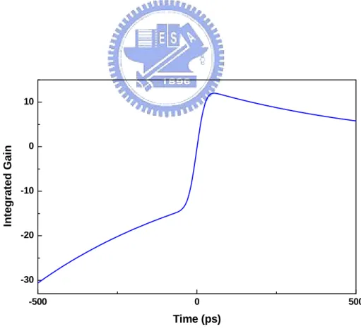
Fig. 2.4 Simulation result of an integrated gain (h(τ)) in the SOA under dark-optical-comb injection.
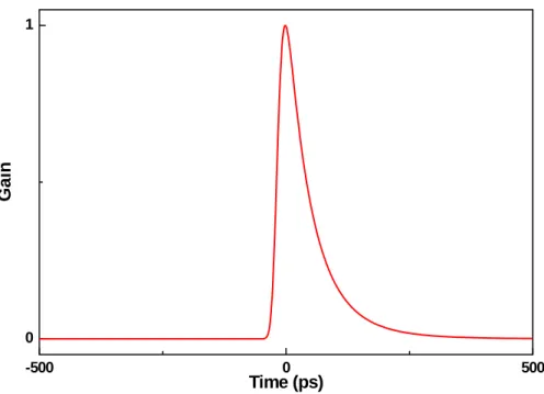
Fig. 2.5 Simulation of the transient gain (G(τ)) in the SOA under dark-optical-comb injection.
Fig. 2.6 Simulation of the transient power gain, G(τ), of SOA backward injected by dark-optical-comb at different small-signal gain conditions.
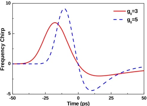
Fig. 2.7 Simulation of the dynamic frequency chirp induced by the backward dark-optical-comb injected SOA at different small-signal gain conditions.
tunable laser; MZM: Mach-Zehnder modulator; SOA: semiconductor optical amplifier; OBPF: optical bandpass filter; OC: optical circulator; Amp.: rf amplifier; NRZ PRBS: nonreturn-to-zero pseudorandom binary sequence; RZ PRBS: return-to-zero pseudorandom binary sequence.
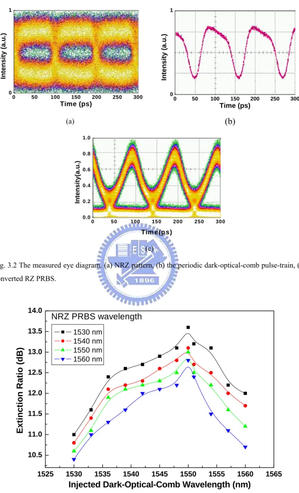
Fig. 3.2 The measured eye diagram. (a) NRZ pattern, (b) the periodic dark-optical-comb pulse-train, (c) converted RZ PRBS.
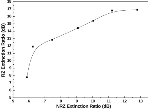
Fig. 3.3 Extinction ratio of the transformed pulsed data-pattern versus the injecting clock wavelength at different data wavelengths.
Fig. 3.4 The input ER (NRZ format) versus the output ER (RZ format).
Fig. 3.5 The BER measurements of back-to-back transmitted NRZ and NRZ-to-RZ data streams at different received powers.
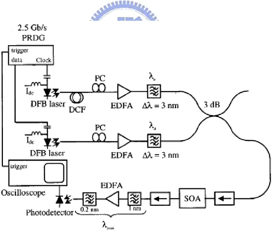
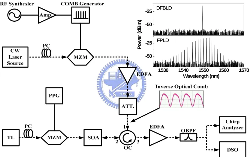
Fig. 4.1 Experimental setup. Amp.: amplifier.; ATT.: optical attenuator; DSO: digital sampling oscilloscope; EDFA: erbium doped fibre amplifier; OBPF: optical band-pass filter; OC: optical circulator; PC: polarization controller; PPG: PRBS pattern generator; TL: tunable laser. Electrical path: solid line. Optical path: dash line.
Fig. 4.2 Temporal traces of (a) multi-wavelength dark-optical-comb and (b) converted pulsed RZ signal, (c) and (d) are corresponding chirps at injected powers of 16.5 dBm (solid) and 2.4 dBm (dashed).
Fig. 4.3 Temporal traces of (a) single-wavelength dark-optical-comb and (b) converted pulsed RZ signal, (c) and (d) are corresponding chirps at injected powers of 16.5 dBm (solid) and 2.4 dBm (dashed).
Fig. 4.4 Gain and the peak to peak chirp of the converted pulsed RZ signals by the single- / multi-wavelength dark-optical-comb injection as a function of the dark-optical-comb injection
power.
Fig. 4.5 FWHM and the peak to peak chirp of the converted pulsed RZ signals by the single- / multi-wavelength dark-optical-comb injection as a function of the dark-optical-comb injection power.
Fig. 4.6 The gain spectrum of SOA at different bias currents.
Fig. 4.7 Dynamic frequency chirp of SOA converted RZ pulsed data under single- (dashed) and multi-wavelength (solid) dark-optical-comb injection vs. injection power at different biased currents of SOA.
Chapter 1
Introduction
1.1
Historical Review of All-optical Format
Conversion Techniques
Future all-optical networks are likely to be a combination of optical-time-division multiplexing (OTDM) and wavelength-division multiplexing (WDM) networks by taking the advantages of both technologies. The nonreturn-to-zero (NRZ) modulation format usually employed in WDM networks requires less bandwidth per channel and has greater timing tolerance, while the return-to-zero (RZ) modulation format used in OTDM networks provides high-bit-rate transmission with better tolerance in fiber nonlinearities and dispersion in the case of soliton transmission. Within the access networks, WDM systems with NRZ modulation format are desirable to provide low-bit rate optical communication between the optical line terminators in the central office and the optical network units on the subscriber side. To handle the increasing amount of the internet traffic, high-bit-rate OTDM systems may be more suitable in the core networks to increase the per-channel capacity by time multiplexing different RZ channels with bit-interleaving. Hence, the conversion between several low-bit-rate NRZ signals and a single high bit-rate RZ signal may be an essential function at the edge nodes of hybrid OTDM-WDM high speed optical communication systems [1.1-1.3]. To date, various all-optical techniques for NRZ-to-RZ format conversion have been demonstrated by using versatile laser diode or semiconductor optical amplifier (SOA) such as a dual-wavelength injection locking of a Fabry–Perot laser diode (FPLD) [1.4], an injection-locked FPLD at un-lasing condition [1.5-1.7], a
cross-gain compression-based wavelength converter [1.8], a gain-modulated semiconductor optical amplifier (SOA) [1.9], four-wave mixing (FWM) in SOA [1.10, 1.11], a Mach–Zehnder interferometer using SOA [1.12], a nonlinear loop mirror with either SOA [1.13, 1.14], a nonlinear optical loop mirror (NOLM) [1.15, 1.16], and an optoelectronic oscillator (OEO) [1.17, 1.18].
1.2 All-optical Nonreturn-to-Zero (NRZ) to
Return-to-Zero (RZ) Data Format Conversion by
using Semiconductor Optical Amplifiers (SOAs)
According to previous researches [1.9-1.18], we know that the format conversion from NRZ to RZ can be obtained by manipulating the gain of device through an optical or an electrical method. Such a concept will be employed in an SOA-based NRZ-to-RZ data format converter. The use of SOA as the nonlinear medium has received considerable attention in terms of high nonlinearity, and optical integration. For example, Ref. [1.9] is using directly gain modulation since it is attractive for its simple implementation for NRZ to RZ conversion, whose experimental setup as shown in Fig. 1.1. On the other hand, FWM scheme is effective due to its transparency to all optical modulation format as well as high bit rate capabilities (see Fig. 1.2).
Some of SOA-based interferometric schemes are also proposed, such as a Mach-Zehnder interferometer (MZI) (see Fig. 1.3) and nonlinear loop mirror (see 1.4). The configuration of MZI in order to transfer the phase modulation into amplitude modulated signal. The advantage of this scheme is the low operation power needed as well as the ability to improve the signal quality of the converted signal with respect to extinction ratio and chirp.
1.3 Motivation of a Novel SOA-based NRZ to RZ
Data Format Conversion by a Backward Injected
Dark-optical-comb
SOA based ultrafast all-optical signal processors have recently emerged for future all optical networks, which include functions such as clock recovery, wavelength conversion, logic operation, and particularly data format conversion between NRZ and RZ for integrating WDM and OTDM architectures, etc. Recently, Lin et al. [1.19] proposed the manipulation on the duty-cycle of a backward optical injection pattern to induce modulation and mode-locking of a SOA-based fiber laser, such a backward dark-optical-comb injection was proposed to shorten the gain window and optimize the mode-locking of SOA[1.20]. The modified cross-gain-depletion architecture benefits from the precise gain control in time domain, the high optical modulation bandwidth, and the improved rising/falling time of SOA. In this thesis, we try to employ the dark-optical-comb injected SOA with a narrowing gain window, which should be an alternative to achieve the high bit-rate NRZ-toRZ data pattern transformation.
1.4 Structure of Thesis
Chapter 1 is an introductory chapter consists of an introduction to suited modulation formats for the OTDM/WDM network applications and the proposed NRZ to RZ format conversion methods of our research. Chapter 2 derives the formula of the SOA gain. First, we will give a traditional Gaussian input pulse shape into SOA, which is introduced by Agrawal et al., to derive the expression of the gain of SOA. Furthermore, we can derive the similar expression of SOA gain under dark-optical-comb injection which is like an inverse Gaussian pulse shape in our
case. In chapter 3, we demonstrate a 10 GHz dark-optical-comb backward injected SOA for all-optical 10Gbit/s NRZ to RZ format conversion. In chapter 4, a multi-wavelength dark-optical-comb injection is employed to temporally and spectrally slice the SOA gain with a smaller gain spectrum, which leads to induce a smaller frequency chirp compare with a single-wavelength injection. At last, chapter 5 concludes our experimental results.
1.5 References
[1.1] D. Norte, E. Park, and A. E. Willner, “All-optical TDM-to-WDM data format conversion in a dynamically reconfigurable WDM network,” IEEE Photon. Technol. Lett. 7, 920–922 (1995).
[1.2] D. Norte and A. E. Willner, “Multistage all-optical WDM-to-TDM-to-WDM and TDM-to-WDM-to-TDM data-format conversion and reconversion through 80 km of fiber and three EDFA’s,” IEEE Photon. Technol. Lett., vol. 7, 1354–1356 (1995).
[1.3] H. Sotobayashi, W. Chujo, and T. Ozeki, “Hierarchical hybrid OTDM/WDM network,” in Proc. IEEE/LEOS Summer Topics, Mont Tremblant, QC, Canada, WF3-47 (2002).
[1.4] C. W. Chow, C. S. Wong, and H. K. Tsang, “All-optical NRZ to RZ format and wavelength converter by dual-wavelength injection locking,” Opt. Commun. 209, 329–334 (2002).
[1.5] Y.-C. Chang, Y.-H. Lin, J. H. Chen, and G.-R. Lin, “All-optical NRZ-to-PRZ format transformer with an injection-locked Fabry-Perot laser diode at unlasing condition,” Opt. Express 12, 4449-4456 (2004).
conversion in synchronously modulated single-mode Fabry-Perot laser diode using external injection-locking-induced nonlinear threshold reduction effect,” IEEE Photon. Technol. Lett. 17, 1307-1309 (2005).
[1.7] Y.-C. Chang and G.-R. Lin, “Injection-locking laser-diode-based OC-192 optical non-return-to-zero-to-return-to-zero OR logic gate,” Opt. Lett. 30, 2074-2076 (2005).
[1.8] J. P. R. Lacey, M. V. Chan, R. S. Tucker, A. J. Lowery and M. A. Summerfield, “All-optical WDM to TDM transmultiplexer,” Electron. Lett. 30, 1612-1613 (1994).
[1.9] D. Norte and A. E. Willner, “Demonstration of an all-optical data format transparent WDM-to-TDM network node with extinction ratio enhancement for reconfigurable WDM networks,” IEEE Photon. Technol. Lett. 8, 715-717 (1996).
[1.10] C. Gosset and G.-H. Duan, “Extinction ratio improvement and wavelength conversion based on four-wave mixing in a semiconductor optical amplifier,” IEEE Photon. Technol. Lett. 13, 139–141 (2001).
[1.11] A. Reale, P. Lugli, and S. Betti, “Format conversion of optical data using four-wave mixing in semiconductor optical amplifiers,” IEEE J. Sel. Topics Quantum Electron. 7, 703–709 (2001).
[1.12] L. Xu, B. C.Wang, V. Baby, I. Glesk, and P. R. Prucnal, “All-optical data format conversion between RZ and NRZ based on a Mach-Zehnder interferometric wavelength converter,” IEEE Photon. Technol. Lett. 15, 308–310 (2003).
[1.13] E. Granot, S. Ben-Ezra, R. Zaibel, H. Chayet, N. Narkiss., N. Shahar, S. Sternklar, S. Tsadka, and P. R. Prucnal, “Extinction ratio improvement by an
all-optical signal regenerator with a semiconductor optical amplifier and a Sagnac loop,” Opt. Commun. 266, 80-87 (2006).
[1.14] C. G. Lee, Y. J. Kim, C. S. Park, H. J. Lee, and C.-S. Park, “Experimental demonstration of 10-Gb/s data format conversions between NRZ and RZ using SOA-loop-mirror,” J. Lightw. Technol. 23, 834–841 (2005).
[1.15] S. Bigo, E. Desurvire, S. Gauchard and E. Brun, “Bit-rate enhancement through optical NRZ-to-RZ conversion and passive time-division multiplexing for soliton transmission systems,” Electron. Lett. 30, 984-985 (1994).
[1.16] H. K. Lee, K. H. Kim, J. T. Ahn, M.-Y. Jeon, and E.-H. Lee, “All-optical format conversion from NRZ to RZ signals using a walk-off balanced nonlinear fibre loop mirror,” Electron. Lett. 32, 2335-2336 (1996).
[1.17] L. Huo, Y. Dong, C. Lou, and Y. Gao, “Clock extraction using an optoelectronic oscillator from high-speed NRZ signal and NRZ-to-RZ format transformation,” IEEE Photon. Technol. Lett. 15, 981-983 (2003). [1.18] J. Lasri, P. Devgan, V. S. Grigoryan, P. Kumar, “Multiwavelength NRZ-to-RZ
conversion with significant timing-jitter suppression and SNR improvement,” Opt. Commun. 240, 293-298 (2004).
[1.19] G.-R. Lin, Y.-S. Liao, and G.-Q. Xia, “Dynamics of optical backward-injection-induced gain-depletion modulation and mode locking in semiconductor optical amplifier fiber lasers,” Opt. Express 12, 2017-2026 (2004).
[1.20] G.-R. Lin, I.-H. Chiu, and M.-C. Wu, “1.2-ps mode-locked semiconductor optical amplifier fiber laser pulses generated by 60-ps backward dark-optical comb injection and soliton compression,” Opt. Express 13, 1008-1014 (2005).
Fig. 1.1 All-optical NRZ to RZ by directly modulated SOA gain.
Fig. 1.3 Principle of NRZ to RZ conversion by using a MZI wavelength converter
Chapter 2
Theoretical Gain Model of Dark-optical-comb
Injected Semiconductor Optical Amplifier
2.1
Theoretical Formula in General Case for Gaussian
Pulse Injection
Because SOAs have large optical bandwidth (e.g. a wavelength bandwidth of 30 nm in the 1.55 m region corresponds to a frequency bandwidth of 3.7 THz) they are able to amplify pulses as short as a few picoseconds. However, gain saturation in the amplifier leads to pulse distortion. When a SOA is used to amplify optical pulses with temporal characteristics of the order of the amplifier transit time (i.e. picoseconds), it is necessary to model pulse propagation through the amplifier with a traveling wave equation containing spatial and time derivatives. In the following model we follow the method of [2.1], where the main assumption is that the pulse width is greater than the intraband relaxation time (usually <0.1ps). If we consider the optical signal evolution in the SOA under a slowly varying envelope approximation can express as [2.2, 2.3]
(
)
( )
( )
( ), 1 1 1 2 , , e g j z t out A A i gA z t A z t P z t eφα
υ
∂ + ∂ = − ∂ ∂ = , (2.1.1)where A is the output amplitude, Pout (z, t) and φ is the signal power and phase respectively, υg is the group velocity, the parameter αe is a linewidth enhancement factor denoting as the ratio of the refractive-index variation to the gain variation under a transient change in pumping carrier density. Assuming the gain of SOA varies
approximately linear with the carrier density (n) or carrier numbers (N) in a volume V, which is also a function of the spectral distribution of carriers, as described by [2.4]
(
)
(
)
(
)
( )
2 0 2 , 1 N g g λ N a n n λ λ λ ⎡ − ⎤ ⎢ ⎥ = Γ − + ⎢ Δ ⎥ ⎣ ⎦ , (2.1.2)where Δλg denotes as the 3-dB spectral linewidth of the SOA gain, λN is the peak wavelength at carrier density n, a is the differential gain coefficient, Γ is the waveguide confinement factor of the SOA, and n0 is the carrier density required for transparency. A transform among variables of τ=t–z/υg is introduced to simplify the solution, which leads to dPout/dz=gPout and ∂φ/∂z=-αeg/2, and the rate equation of carrier density can be re-written as
( )
2 0 0 out c c g A gP dn I n I n d eV h V eV h Vτ
τ
= −τ
−ν
= −τ
−ν
, (2.1.3)where I is the biased current of SOA and τc is the spontaneous carrier lifetime. Eq. (2.1.3) can then be transformed into a rate equation for g,
( )
0 out c sat gP g g dg d Eτ
τ
τ
− = − , (2.1.4)where the small-signal gain of SOA denotes as g0 = Γa(Iτc/e-N0)/V= Γan0(I/I0-1) with I0 = eVn0 /τc, Esat=hν0σ/a is the saturation energy with a modal cross-section ofσ=V/ΓL, and L is the length of the SOA. The solution of Eq. (2.1.4) is
( )
( )
exp( )
( ) ( )
out in in P τ =P τ ⎡⎣h τ ⎦⎤≡P τ G τ , (2.1.5) with( )
0( )
,
h
τ
=
∫
τg z
τ
dz
, (2.1.6)in which h(τ) is the integrated gain at each point of the propagating pulse profile, Pin(τ) and Pout(τ) are the temporally varied input and output power function respectively. Integrating Eq. (2.1.4) and using Eq. (2.1.6) gives an ordinary differential equation for
h,
( )
(
)
0 in h 1 c sat P g L h dh e d Eτ
τ
τ
− = − − . (2.1.7)For a given input pulse shape and gain g0L, Eq. (2.1.7) can be solved to obtain h (τ). Pout can then be found using Eq. (2.1.5). Eq. (2.1.7) can be solved analytically in one important case. If the pulse width τp << τc the first term on the RHS of Eq. (2.1.7) can be neglected. This is because the pulse width is so short that the gain has no time to recover. In this case the solution of Eq. (2.7) is
( )
( )
0 1 ln 1 1 exp in sat U h G E τ τ = − ⎪⎧⎨ − −⎛⎜ ⎞⎟ ⎡⎢− ⎤⎥⎫⎪⎬ ⎪ ⎝ ⎠ ⎣ ⎦⎪ ⎩ ⎭, (2.1.8)Where G0 = exp (g0L) is the unsaturated signal-pass amplifier gain and
( )
( )
in in
U τ τ P τ dτ
−∞ ′ ′
=
∫
(2.1.9)Uin is the energy contained in the pulse up to time τ. Uin(∞) is the total pulse energy Ein. As an example consider a Gaussian input pulse shape
( )
22 0 0 exp in in E Pτ
τ
τ
τ π
⎛ ⎞ = ⎜− ⎟ ⎝ ⎠ (2.1.10)τ0 is related to the pulse full width at half maximum τp by τp ~ 1.665τ0. Inserting (2.1.10) in (2.1.9) gives
( )
(
0)
1 1 2 in in U τ = E ⎡⎣ +erf τ τ ⎤⎦ (2.1.11)where erf is the error function. The transient amplifier gain is
( )
( )
( )
1 0 1 exp 1 1 exp in sat U G h G E τ τ τ − ⎧ ⎛ ⎞ ⎡ ⎤⎫ ⎪ ⎪ = ⎡⎣ ⎤ ⎨⎦= − −⎜ ⎟ ⎢− ⎥⎬ ⎪ ⎝ ⎠ ⎣ ⎦⎪ ⎩ ⎭ (2.1.12)2.2 Theoretical Formula for Dark-optical-comb
Injection
In contrast to previous work of section 2.1 on the theoretical derivation of the SOA gain function, the function form of the optical gain of the SOA in our case is relatively simple as compared to the amplifier gain obtained under typical operation of the SOA. Since the gain window of the SOA is temporally modified to implement re-amplifying, re-shaping, and re-timing of the incoming NRZ data-stream, as illustrated in Fig. 2.1. Theoretically, the transfer function of transient gain for the SOA under backward dark-optical-comb injection can be deduced by modifying the similar model described above. It is necessary to re-model the temporally gain-depleted SOA by assuming the backward dark-optical-comb injection function with a form of Pin (τ) = P0 [1-P’ (τ)], where P’ (τ) exhibits a Gaussian pulse shape. That is,
( )
22 0 0 1 exp in in E P τ τ τ τ π ⎡ ⎛ ⎞⎤ = ⎢ − ⎜− ⎟⎥ ⎝ ⎠ ⎣ ⎦, (2.2.1)where the first-term on right-handed side (RHS) of Eq. (2.2.1) is used to complete deplete the SOA gain by inducing stimulated emission at the injecting wavelength, and the second-term leaves the residual gain window of the SOA with a very short duty-cycle within one period. This input power function precisely describes the waveform of a backward injected dark-optical-comb before entering into the SOA.
Under an appropriate backward injecting power, the dark-optical-comb (i.e. an inverse Gaussian shape with a small duty cycle in one period) can fully deplete most of the SOA gain within one period, as illustrate in Fig. 2.2. This eventually leads to a narrowing effect on the residual gain window of the SOA, which remains only a Gaussian shape with a small duty cycle.
( )
2 2 0 0 0 0 2 0 2 0 0 0 1 exp exp in in c sat c sat in in c sat sat E P g L h g L h dh d E E g L h E E E E τ τ τ π τ τ τ τ τ τ τ π τ π τ ⎡ ⎛ ⎞⎤ − − ⎢ ⎜ ⎟⎥ − − ⎣ ⎝ ⎠⎦ = − = − ⎛ − ⎞ ⎛ ⎞ =⎜⎜ − ⎟⎟+ ⎜− ⎟ ⎝ ⎠ ⎝ ⎠ . (2.2.2)That is, the maximum backward injection energy is set as Pin = Ein/τ0π-1/2 ≈ [g0L/τc]Esat in our case. With the backward injection, the original SOA gain can almost be depleted in one period. That is, the first term in RHS of Eq. (2.2.2) can be neglected by cancelling each other. Concurrently, the residual gain becomes the inverse shape of the incident waveform with its coefficient equivalent to the maximum gain of the SOA. Therefore, we can simplify and re-write Eq. (2.2.2) as
2 0 2 0 exp c c g L dh h d τ τ τ τ τ ⎛ ⎞ = ⎜− ⎟− ⎝ ⎠ , (2.2.3)
and the Eq. (2.2.3) can be solved to obtain h(τ) for a given input inverse pulse shape and gain g0L. The solution of Eq. (2.2.3) is
( ) ( ) 2 2 2 2 0 0 2 0 2 2 0 2 0 0 4 0 0 0 0 4 0 0 0 0 2 2 2 2 c c c c c c f d f d c c c c c c g L g L h e e e d e e e d g L e e erf g L e erf τ τ τ τ τ τ τ τ τ τ τ τ τ τ τ τ τ τ τ τ τ τ τ τ πτ τ τ τ τ τ τ π τ τ τ τ τ − − − − − − ⎡ ⎤ ∫ ⎢ ∫ ⎥ = ⋅ = ⋅ ⋅ ⋅ ⎢ ⎥ ⎣ ⎦ ⎡ ⎤ ⎢− ⎛ ⎞⎥ = ⋅ ⋅⎢ ⎜ − ⎟⎥ ⎝ ⎠ ⎢ ⎥ ⎣ ⎦ ⎛ ⎞ = − ⎜ − ⎟ ⎝ ⎠
∫
∫
, (2.2.4)where erf denotes the error function. Therefore,
( )
( )
0 0 02 02
0
exp exp exp
2 c 4 c c 2 c g L G τ h τ τ π τ τ erf τ τ τ τ τ τ τ ⎧ ⎛ ⎞ ⎛ ⎞⎫ ⎪ ⎪ = ⎡⎣ ⎤⎦= ⎨− ⎜ − ⎟ ⎜ − ⎟⎬ ⎪ ⎝ ⎠ ⎝ ⎠⎪ ⎩ ⎭. (2.2.5)
As a result, G(τ) is the transfer function of transient gain for the SOA under backward dark-optical-comb injection with an inverse Gaussian like waveform. The
simulation results of the injected dark-optical-comb, reshaped h(τ) and G(τ) of the SOA, as shown in Figs. 2.3, 2.4 and 2.5, respectively. The normalized on-level of the input power function shown in Fig. 3 first reduces the SOA gain to below transparent (i.e. loss) condition. Subsequently, the SOA gain build up again within the instantaneous off-level of the power function, providing a short rising-edge but long trailing-edge small-signal gain function. Such an operation eventually reshapes the continuous-wave gain of the SOA into a greatly shortened gain window, as shown in Fig. 2.5.
On the other hand, the dynamic frequency chirp imposed on the output of SOA can be derived from the phase modulation due to the carrier-induced transient variation on refractive index and gain of the SOA is obtained by differentiating the phase modulation as [2.5, 2.6]
(
)
2 0 2 2 2 2 0 0 0 2 2 4 0 0 0 0 0 0 0 4 0 0 0 4 2 2 2 0 0 2 1 2 1 1 1 2 2 ( ) 4 2 4 2 c c c c c c c c c e g c e sp g L e erf c e c c d d a n n dP R P d g L e erf g Le e τ τ τ τ τ τ τ τ τ τ τ τ τ π τ τ τ τ τ τ τ τ τ φ ν π τ α υ π τ α τ π τ τ τ τ π τ τ α π τ τ − − ⎛ ⎞ − −⎜ − ⎟ ⎛ ⎞ ⎝ ⎠ − ⎜ − ⎟ ⎝ ⎠ Δ = − ⎧ ⎡ ⎤⎫ ⎪ ⎪ = − ⎨− ⎢Γ − − ⎥⎬ ⎪ ⎣ ⎦⎪ ⎩ ⎭ ⎛ ⎞ = ⎜ − ⎟ ⎝ ⎠ ⎡ ⎛ ⎞ ⎢ ⎜ − ⎟ ⎢ ⎝ ⎠ = ⎢ + ⎣ i ( )( )
( )
1 1 2 4 in sat P f E e in sat c f P e f E τ τ α τ π τ − ⎤ ⎥ ⎥ ⎥ ⎢ ⎥ ⎢ ⎥ ⎦ ⎡ ⎤ = ⎢ + ⎥ ⎣ ⎦ (2.2.6) The simulation on transient gain and dynamic frequency chirp of the SOAinjected by dark-optical-comb are shown in Fig. 2.6 and 2.7, respectively. These results corroborate that the dynamic frequency chirp of the SOA converted pulse data
exhibits a strong dependence on the injected dark-optical-comb power and pulsewidth. The reduction on the duty-cycle of injected dark-optical-comb although shortens the pulsewidth of the converted pulsed data bit, which also induces a larger frequency chirp since an equivalent gain depletion level is accomplished within a narrower time window.
2.3 References
[2.1] G. P. Agrawal and N. A. Olsson, “Self-phase modulation and spectral broadening of optical pulses in semiconductor laser amplifiers,” IEEE J. Quantum Electron. 25, 2297-2306 (1989)
[2.2] M. J. Connelly, Semiconductor optical amplifiers, Kluwer Academic Publishers, Boston, ch. 5 (2002).
[2.3] G. P. Agrawal and N. A. Olsson, “Amplification and compression of weak picosecond optical pulses by using semiconductor laser amplifiers,” Opt. Lett.,
14, 500-502 (1989).
[2.4] A. E. Willner and W. Shieh, “Optimal spectral and power parameters for all-optical wavelength shifting: single stage, fanout, and cascadability,” J. Lightwave Technol. 13, 771-781 (1995).
[2.5] G. Walter, A. James, N. Holonyak, Jr., and M. Feng, “Chirp in a transistor laser: Franz-Keldysh reduction of the linewidth enhancement,” Appl. Phys. Lett. 90, 091109 (2007).
[2.6] T. Watanable, N. Sakaida, H. Yasaka, and M. Koga, “Chirp control of an optical signal using phase modulation in a semiconductor optical amplifier,” IEEE Photon. Technol. Lett. 10, 1027-1029 (1998).
Fig. 2.1 Illustration of the NRZ to RZ processes in a SOA under dark-optical-comb injection.
Fig. 2.2 The temporally reshaped gain window of the SOA format converter (right) under the backward injection of dark-optical-comb (left).
-500 0 500 0 1 Inte ns ity (a . u. ) Time (ps)
Fig. 2.3 Simulated shape of a dark-optical-comb signal within in one period.
-500 0 500 -30 -20 -10 0 10 In te g ra te d G a in Time (ps)
-500 0 500 0 1 Ga in Time (ps)
Fig. 2.5 Simulation of the transient gain (G(τ)) in the SOA under dark-optical-comb injection.
-50 -25 0 25 50 0.0 0.2 0.4 0.6 0.8 1.0 g 0=3 g 0=5 N o rm a lrize d Ga in (a .u.) Time (ps)
Fig. 2.6 Simulation of the transient power gain, G(τ), of SOA backward injected by dark-optical-comb at different small-signal gain conditions.
-50 -25 0 25 50 -5 0 5 10 g0=3 g 0=5 Fre quency Chirp Time (ps)
Fig. 2.7 Simulation of the dynamic frequency chirp induced by the backward dark-optical-comb injected SOA at different small-signal gain conditions.
Chapter 3
10 Gbit/s All-Optical NRZ-to-RZ Data Format
Conversion Based on a Backward
Dark-Optical-Comb Injected Semiconductor
Optical Amplifier
3.1 Introduction
All-optical conversion between nonreturn-to-zero (NRZ) and return-to-zero (RZ) data-streams is necessary for interfacial linking between time and wavelength division multiplexed (TDM and WDM) networks, which can typically be implemented using such as nonlinear optical loop mirrors [3.1], ultrafast polarization bistable vertical-cavity surface-emitting lasers (VCSELs) [3.2], semiconductor optical amplifiers (SOAs) [3.3, 3.4], SOA-based interferometers [3.5, 3.6], electroabsorption-modulation (EAM) based self-starting optoelectronic oscillator (OEO) [3.7], and dual-wavelength injection-locked Fabry-Perot laser diode at un-lasing condition [3.8]. The SOA is a frequently used to achieve NRZ-to-RZ data format conversion via either four-wave mixing (FWM) [3.3] or direct electrical modulation technique [3.4]. The directly electrical-modulated bandwidth of SOA is limited at <10 GHz. Although the FWM technique has capabilities of transparency to modulation format and high-bit-rate operation, which still suffers from problems of low conversion efficiency and intrinsic polarization sensitivity. In this work, we demonstrate for the first time 10 Gbit/s all-optical NRZ-to-RZ data format conversion with an optically gain controlled SOA, which is backward injected by a
dark-optical-comb re-shaping from the received optical clock at 10 GHz. Such a polarity non-inverted and wavelength-maintained data format converter can be operated even though the incoming NRZ data-stream is degraded and without pre-amplification, which presents a simplified architecture with superior performances including large operational bandwidth, enhanced extinction ratio, ultra-low bit-error-rate (BER), and greatly improved power penalty.
3.2 Experimental Setup
The experimental setup of the SOA-based NRZ-to-RZ data format converter is shown in Fig. 3.1, which consists of a SOA, a backward optical injector, an optical circulator (OC), an erbium doped fibre amplifier (EDFA), and an optical band-pass filter (OPBF, f3dB = 1.37 nm). In experiment, an incoming optical NRZ pseudorandom binary sequence (PRBS) data with word length of 231-1 and output power from -10 to -1 dBm is employed. The SOA with gain peak at 1530 nm and amplified spontaneous emission linewidth of 35 nm is operated at 280 mA (high-gain condition).
A dark-optical-comb pulse-train is generated by optically reshaping the received clock signal with a Mach-Zehnder intensity modulator driving by an electrical comb generator [3.9]. To simplify the setup in experiment, a radio frequency (rf) synthesizer (Agilent, E8457A) is used to simulate the received clock signal. The dark-optical-comb pulse-train is then amplified by an EDFA and backward-injected into the SOA through an OC. To effectively saturate the SOA, the injection power of the dark-optical-comb measured at the output port 2 of OC is set as 17.9 dBm. Another EDFA with tunable gain cascaded after the OC is used to adjust the power level of the converted RZ pattern. Both the amplified spontaneous emissions in the SOA and EDFA are filtered out by an OBPF.
3.3 Results and Discussion
The eye-diagram of NRZ PRBS data-stream and the pulse-train of dark-optical-comb with duty-cycle of 70% are shown in Figs. 3.2(a) and 3.2(b), respectively. Under such an intense injection with a dark-optical-comb of relatively large duty-cycle, the gain of SOA can be fully depleted, and only a greatly narrowed gain window with a full-width at half-maximum of 30 ps is left within most of the modulating period. This results in a pulsating operation as well as NRZ-to-RZ data format conversion to the incoming optical NRZ data. The NRZ PRBS data encounters the pulsed gain in the SOA and is format converted to a RZ data pattern, as shown in Fig. 3.2(c).
By contrast, a normal optical pulse injection only causes finite gain-depletion and leaves a broader gain window in the SOA, which inevitably results in a distorted NRZ shape instead of a RZ pattern. The converted RZ PRBS data is remaining at the identical wavelength and the same data polarity to that of the incoming NRZ PRBS data. Such a feature is important for a format converter used at interface of WDM and TDM link. As the NRZ-to-RZ conversion of multi-channel WDM data-streams onto a given wavelength is required for transmission across the TDM network [3.10, 3.11], it is highly desirable to preserve the polarity (non-inversion on the phase of data format) of data-stream between the input WDM channels and the output TDM channel when performing data format conversion. Otherwise, the addition of additional overhead prior to the TDM packet header is necessary in order to correct its data polarity.
The extinction ratio is determined by accounting into both the gain depletion and gain-spectral shifting effects occurring in the SOA under high power injection. The peak wavelength of the SOA gain can be shifted from 1530 to 1550 nm under the strong backward injection at 1550 nm. Such a spectral shift in the SOA can be realized by the
expression of λN =λ0-κ0(N-N0) [3.12], where λN is the peak wavelength at carrier density N, λ0 is the peak wavelength at transparency, κ0 is a constant characterizing the gain-peak shift, N is the carrier concentration, and N0 is the carrier concentration at transparency. The shift of SOA gain peak to a longer backward injecting wavelength is mainly attributed due to the depletion of carriers in the SOA by the intense dark-optical-comb injection. It is preferred to locate the injected dark-optical-comb at wavelengths near but slightly longer than the gain peak, as the gain SOA can be depleted more severely at larger gain region and thus red-shifted to a longer wavelength. This eventually leads to a higher extinction ratio of the input data-stream at shorter wavelengths as the gain of SOA is changing from saturation to depletion condition.
However, the depletion of carriers as well as gain of the SOA becomes less significant if a backward injecting wavelength is too long to exceed the original gain peak, which in turn causes a reduction in extinction ratio of the input data-stream at shorter wavelengths. As shown in Fig. 3.3, the extinction ratio of the converted RZ PRBS data-stream is dependent on the wavelength of backward dark-optical-comb injection, which reveals a largest extinction ratio with a backward injection at 1550 nm when setting the NRZ PRBS data at shorter wavelengths. The extinction ratio (ER) (i.e. power ratio of the transmitted “1” data to the transmitted “0” data) of the incoming NRZ PBRS data is about 7.13 dB. After conversion, the measured eye diagram for the RZ PRBS data in Fig. 3.2(c) reveals a greatly improved extinction ratio of 13.6 dB. To investigate the minimum ER of the input NRZ in which the ER can still be greatly improved at the output RZ, the input ER versus output ER is measured, as shown in Fig. 3.4. The input ER larger than 6.24 dB can be converted into RZ format with ER of 11.92. The output ER will increase with the increase of the input ER. Note that when the input ER is larger than 11 dB the output ER will saturate.
The BER of the back-to-back (BtB) NRZ PRBS and converted RZ PRBS data-streams at 10 Gbit/s are measured as function of received data power, as shown in Fig. 3.5. The nearly error-free (BER < 10-12) BtB NRZ and RZ PRBS data-streams can be detected at received optical power of larger than -15 and -18.7 dBm, respectively. The BER of the format-converted RZ PRBS data inevitably increases with reduction of the incoming NRZ PRBS data power. Previously, it has been elucidated that high levels of electrical pumping of SOA accompanied by intense optical injection to suppress lasing and enhance carrier/photon interactions, can significantly result in a faster conversion speed than the carrier recovery rate [3.13]. In our case, the increase on both of the data and backward injection power also result in the shortened rising and falling time of signals, respectively. The BER of the converted RZ PRBS can still be 10-9 when the NRZ PRBS data power is <-6 dBm, which further reduces to 10-12 at data power of -1 dBm.
Note that the upper limitation on operational bit-rate is determined by the gain recovery time of the SOA given byτ-1=τnr-1+aS [3.14], where τnr is the non-radiative recombination time, a denotes the stimulated emission rate, and S is the internal photon density in the SOA. When the backward injected dark-optical-comb pulse-train turns off, low and high levels of the optical NRZ PRBS provide different photon density and encounter different gain recovery time in the SOA. Such a mechanism further improves the BER performance of the converted RZ PRBS. A negative power penalty [3.15] of -3.7 dB is measured at a BER of 10-12, which has already exceeded the performance of a previous SOA-based fiber-loop-mirror configuration [3.5]. The negative power penalty is attributed to the noise reduction of the data-stream by both the gain-saturated SOA [3.16] and the data format conversion. To date, the proposed data format converter requires only a dark-optical-comb generator and a SOA in
comparison with the complicated FWM and XPM techniques.
3.4 Conclusion
In conclusion, an all-optical NRZ-to-RZ data format converter at bit-rate up to 10 Gbit/s is primarily demonstrated by using a backward dark-optical-comb injected SOA. The wavelength and polarity of the converted RZ PRBS data is preserved with the incoming NRZ PRBS data. The extinction ratio of the incoming NRZ PRBS data and the format-converted RZ PRBS data are 7.13 dB and 13.6 dB, respectively. At 10 Gbit/s, the bit-error rate can be as low as 10-12 at the received optical power of about -18.3 dBm. It is noted that a negative power penalty of about -3.7 dB at a BER of 10-12 is measured, which implies that such a configuration has re-timing, re-shaping, and re-amplifying (3R) capabilities.
3.5 References
[3.1] H. K. Lee, K. H. Kim, J. T. Ahn, M.-Y. Jeon, and E.-H. Lee, “All-optical format conversion from NRZ to RZ signals using a walk-off balanced nonlinear fibre loop mirror,” Electron. Lett. 32, 2335-2336 (1996).
[3.2] H. Kawaguchi, Y. Yamayoshi, and K. Tamura, “All-optical format conversion using an ultrafast polarization bistable vertical cavity surface-emitting laser,” CLEO’00, 379-380 (2000).
[3.3] A. Buxens, H. N. Poulsen, A. T. Clausen, and P. Jeppesen, “All-optical OTDM to WDM signal format translation and OTDM add-drop funcionality using bi-directional four wave mixing in a semiconductor optical amplifier,” Electron. Lett. 36, 156-157 (2000).
transparent WDM-to-TDM network node with extinction ratio enhancement for reconfigurable WDM networks,” IEEE Photon. Technol. Lett. 8, 715-717 (1996).
[3.5] C. G. Lee, Y. J. Kim, C. S. Park, H. J. Lee, and C. S. Park, “Experimental demonstration of 10-Gb/s data format conversions between NRZ and RZ using SOA-loop-mirror,” OSA/IEEE J. Lightwave Technol. 23, 834-841 (2005). [3.6] L. Xu, B. C. Wang, V. Baby, I. Glesk, and P. R. Prucnal, “All-optical data
format conversion between RZ and NRZ based on a Mach-Zehnder interferometric wavelength converter,” IEEE Photon. Technol. Lett. 15, 308-310 (2003).
[3.7] J. Lasri, P. Devgan, V. S. Grigoryan, and P. Kumar, “Multiwavelength NRZ-to-RZ Conversion with Timing-Jitter Suppression using EAM-Based Optoelectronic Oscillator,” Opt. Commun. Vol. 240, 293-298 (2004).
[3.8] Y.-C. Chang, Y.-H. Lin, J. H. Chen, and G.-R. Lin, “All-optical NRZ-to-PRZ format transformer with an injection-locked Fabry-Perot laser diode at unlasing condition,” Opt. Express 12, 4449-4456 (2004).
[3.9] G.-R. Lin, I.-H. Chiu, and M.-C. Wu, “1.2-ps mode-locked semiconductor optical amplifier fiber laser pulses generated by 60-ps backward dark-optical comb injection and soliton compression,” Opt. Express 13, 1008-1014 (2005). [3.10] J. P. R. Lacey, M. V. Chan, R. S. Tucker, A. J. Lowery, and M. A.Summerfield,
“All-optical WDM to TDM transmultiplexer,” Electron. Lett. 30, 1612-1613 (1994). [3.11] D. Norte, E. Park, and A. E. Willner, “All-optical TDM-to-WDM data format
conversion in a dynamically reconfigurable WDM network,” IEEE Photon. Technol. Lett. 7, 920-922 (1995).
a new optical amplifier model,” IEEE J. Quantum Electron. 21, 609-613 (1985).
[3.13] T. Durhuus, B. Mikkelsen, and K. E. Stubkjaer, “Detailed dynamic model for semiconductor optical amplifierstheir crosstalintermodulation distortion,” OSA/IEEE J. Lightwave Technol. 10, 1056-1065 (1992).
[3.14] J. M. Wiesenfeld, B. Glance, J. S. Perino, and A. H. Gnauck, “Wavelength conversion at 10 Gb/s using a semiconductor optical amplifier,” IEEE Photon. Technol. Lett. 5, 1300-1303 (1993).
[3.15] C. W. Chow, C. S. Wong, and H. K. Tsang, “All-optical NRZ to RZ format and wavelength converter by dual-wavelength injection locking,” Opt. Commun.
209, 329-334 (2002).
[3.16] A. D. McCoy, P. Horak, B. C. Thomsen, M. Ibsen, M. R. Mokhtar, and D. J. Richardson, “Improving signal quality in a spectrum-sliced WDM system using SOA-based noise reduction” IEEE Photon. Technol. Lett. 17, 241-243 (2005).
SOA
OBPF
MZM
TL
Comb
RF Synthesizer
Electrical Signal Path
Optical Signal Path
EDFA
EDFA
OC
1
2
3
Amp.
0 1 10 11 10 10 11 1010RZ PRBS
NRZ PRBS
Fig. 3.1 Experimental setup. EDFA: erbium doped fibre amplifier; TL: tunable laser; MZM: Mach-Zehnder modulator; SOA: semiconductor optical amplifier; OBPF: optical bandpass filter; OC: optical circulator; Amp.: rf amplifier; NRZ PRBS: nonreturn-to-zero pseudorandom binary sequence; RZ PRBS: return-to-zero pseudorandom binary sequence.
0 50 100 150 200 250 300 0 1 Intensity (a.u.) Time (ps) (a) 0 50 100 150 200 250 300 0 1 In ten s it y (a.u. ) Time (ps) (b) 0 50 100 150 200 250 300 0.0 0.2 0.4 0.6 0.8 1.0 In tensi ty (a. u. ) Tim e(ps) (c)
Fig. 3.2 The measured eye diagram. (a) NRZ pattern, (b) the periodic dark-optical-comb pulse-train, (c) converted RZ PRBS. 1525 1530 1535 1540 1545 1550 1555 1560 1565 10.5 11.0 11.5 12.0 12.5 13.0 13.5 14.0 E x tin c tio n Ra ti o ( d B)
Injected Dark-Optical-Comb Wavelength (nm)
1530 nm 1540 nm 1550 nm 1560 nm
NRZ PRBS wavelength
Fig. 3.3 Extinction ratio of the transformed pulsed data-pattern versus the injecting clock wavelength at different data wavelengths.
5 6 7 8 9 10 11 12 13 5 6 7 8 9 10 11 12 13 14 15 16 17 18 RZ E x tinc tion Ra tio (dB) NRZ Extinction Ratio (dB)
Fig. 3.4 The input ER (NRZ format) versus the output ER (RZ format).
Fig. 3.5 The BER measurements of back-to-back transmitted NRZ and NRZ-to-RZ data streams at different received powers.
Chapter 4
Duty-Cycle and Chirp Diagnosis of All-Optical
Format Conversion Data in Multi- and
Single-Wavelength Dark-Optical-Comb Injected
Semiconductor Optical Amplifier
4.1 Introduction
Recently, the implementations of all-optical pulsed data transformation in traveling-wave semiconductor optical amplifiers (SOAs) have been comprehensively investigated in combination with versatile techniques such as direct electrical modulation [4.1], four-wave-mixing [4.2], cross-phase modulation, waveguide coupler [4.3] and loop-mirror [4.4] based interferometry. Direct modulation technique inevitably meet bottleneck of low-bit-rate operation due to insufficient bandwidth of the SOA. Four-wave mixing scheme exhibits all-optical and high-speed capabilities but suffers relatively low signal-to-noise ratio and conversion efficiency. The interferometric configurations bear problems either the complicated device fabrication or the requirement on exact delay-time control. To achieve all-optical and high-contrast operations, a temporally gain-sliced SOA was employed to demonstrate pulsed data-format conversion under backward single-wavelength dark-optical-comb injection technique [4.5]. Such a scheme preserves the incoming and transformed data wavelength and provides precise gain control in time domain, thus leading to an enhanced extinction ratio at bit-rate higher than modulation bandwidth of the SOA electrode. However, an extremely large frequency chirping effect usually
accompanies with the cross-gain depletion based all-optical conversion due to large carrier density changed during the signal processing, which inevitably degrade the bit-error-rate performance and reduces the transmission distance without proper wavelength dispersion compensation during propagation [4.6]. In principle, the dynamic frequency chirp of the pulsed data signal from SOA is affected not only by the intense gain modulation in time domain, but also by the reshaped gain profile of the SOA in spectral domain. It is thus worthy of investigating the dynamic gain and chirp behaviors such a SOA under broadband and large duty-cycle optical injection induced cross-gain depletion situation. The theoretical and experimental studies on spectral and temporal gain-shaping of the SOA facilitate a precise control of the dynamic frequency chirp at the pulsed data-stream.
In this work, we establish a dynamic chirp model for the backward dark-optical-comb injected SOA to compare the effect of single- or multi-wavelength injection on both the duty-cycle and the dynamic frequency chirp of the pulsed data all-optical converted by the SOA. By temporally and spectrally reshaping the gain profile of the SOA with such a backward injected multi-wavelength dark-optical-comb, the converted pulse data reveals a smaller frequency chirp than that obtained under the single-wavelength dark-optical-comb injection case. The temporal and spectral dependencies of the SOA gain under single- and multi-wavelength dark-optical-comb injection are derived to elucidate experimental results.
4.2 Experimental Setup
The all-optical pulsed data-format converter is schematically shown in Fig. 4.1, in which a SOA DC-biased at 350 mA with a maximum gain at 1530 nm and an amplified spontaneous emission linewidth of 38 nm at 3-dB decay is employed. The
dark-optical-comb is generated by passing a continuous-wave laser source through an electrical-comb driven Mach-Zehnder intensity modulator (MZM) to temporally reshape the gain-window of the SOA, while the DC-level of the amplified electrical comb pulse at repetition frequency of 10 GHz is slightly offset from zero to obtain maximum modulation depth of the dark-optical-comb. Either a single-wavelength distributed feedback laser diode (DFBLD) with a 3-dB linewidth of 1 MHz, or a multi-wavelength Fabry-Perot laser diode (FPLD) with 3-dB linewidth of 7.297 nm is employed in our experiments for comparison, their corresponding spectra are shown in the inset of Fig. 4.1. A commercial electrical comb generator activated by a 10-GHz sinusoidal clock signal of 30 dBm generates electrical pulse-train of 30-ps pulsewidth, leading to the generation of an dark-optical-comb (see inset of Fig. 4.1) with a duty-cycle of 70 % output from the MZM. After propagating through an erbium-doped fiber amplifier (EDFA) with 20-dB gain and an optical circulator (OC), the dark-optical-comb is used to backward inject and then periodically deplete the gain of SOA for implementing non-return-to-zero to return-to-zero (NRZ-to-RZ) data format conversion. The incoming optical NRZ data-stream is simulated by encoding a tunable laser (TL) with another MZM, which is driven by a pseudo-random-bit-sequence (PRBS) data-stream generator with a pattern length of 223-1. The injection power at the port 2 of the OC is increased to saturate the gain of SOA for obtaining maximum extinction ratio of the converted pulsed data. The wavelength, input power and extinction ratio (defined as the ratio of the “on level power” to the “off level power”) of the incoming optical NRZ PRBS data are 1529.2, -15 dBm and 12 dB, respectively. The dark-optical-comb is set at longer wavelength to achieve a better extinction ratio of the converted signal will be obtained at the output [4.7]. Afterwards, the converted RZ data is analyzed by a chirp analyzer (Advantest
Q7606B) to obtain its dynamic frequency chirp at different dark-optical-comb injection power.
4.3 Results and Discussion
In experiment, the input NRZ data is converted into a pulsed RZ data with an improved extinction ratio of 15.5 dB in the SOA under an dark-optical-comb injection power of 16.5 dBm. Temporal traces of the dark-optical-comb, the converted pulsed RZ data bit, and the corresponding dynamic frequency chirp obtained under multi- and single-wavelength injection conditions are shown in Fig. 4.2 and 4.3, respectively. The peak-to-peak frequency chirp related to the input NRZ signal, the multi- and single-wavelength dark-optical-comb are determined as 1.0, 2.1 and 1.9 GHz, respectively. As the injection power of the dark-optical-comb increasing from 2.4 to 16.5 dBm, the FWHM of the converted RZ signal is shortened from 41.2 to 31.6 ps, however, the peak-to-peak frequency chirp of the pulsed RZ data bit is concurrently enlarged from 6.7 to 11.1 GHz by using the multi-wavelength dark-optical-comb injection.
In contrast to the multi-wavelength injection, the injection of single-wavelength dark-optical-comb with same power level only consumes the carriers pumped upon the states with energy larger than injecting photons in the SOA. Therefore, the carriers left at low energy levels only accounts for the amplified spontaneous emission, which eventually contributes to the DC-level of the data-stream and causes a limited extinction ratio of the converted RZ pulse. Under the single-wavelength dark-optical-comb injection, the FWHM of the converted RZ signal is shortened from 37.3 to 30.8 ps as the injection power from 2.4 to 16.5 dBm, whereas the peak-to-peak frequency chirp of the pulsed RZ data bit is increased from 9.1 to 13.2 GHz.
Apparently, the single-wavelength dark-optical-comb injection shortens the converted RZ pulsewidth at a cost of enlarged dynamic frequency chirp as compared to the multi-wavelength case. Theoretically, the gain coefficient of SOA exhibits a Lorentzian lineshape described determined by both the pumped carrier concentration and the spectral distribution [4.8], as described in Eq. (2.1.2). The pulsed RZ data-format conversion occurred in SOA under the intense cross-gain depletion process not only results in patterning effect in time domain, but also induces a large chirp with its level proportional to the depth of gain depletion. Nonetheless, the residual gain as well as the gain depletion depth of SOA can be minimized if we further shrink the gain distribution profile of SOA in spectral domain, since the derivative of gain coefficient to its spectral linewidth is always greater than zero,
(
)
2( )
3(
)
2 , , 2 0 N N N g N g g dg g d λ λ λ λ λ λ λ λ λ = − ⎡⎢⎣ Δ + − Δ ⎤⎥⎦> Δ . (4.3.1)Therefore, the dynamic frequency chirp of the converted RZ pulse is further reduced by shrinking the gain distribution of SOA in spectral domain. Temporal and spectral slicingon the gain of SOA can simultaneously be implemented by introducing a multi-wavelength dark-optical-comb injection into the SOA.
In more detail, the effect of the backward dark-optical-comb injection power on the gain of the SOA, the converted RZ pulsewidth, and the peak-to-peak chirp performance of the converted pulsed RZ at different injection conditions are analyzed and shown in Fig. 4.4 and 4.5. Figure 4.4 shows the gain and peak to peak chirp as a function of dark-optical-comb injection power. The peak to peak chirp is increased as increasing injection power, since the phase of the converted signal rapidly increases due to carrier-induced index changes. In particular, the fluctuations on measured frequency chirp with changing injection power is due to the interference occurred
between the injected and partially reflected dark-optical-combs in SOA. Such an intense injection induced interference changes the carrier and gain dynamics in SOA and thus affects the pulse shape and dynamic frequency chirp [4.9]. On the other hand, for general optical time-division-multiplexing (OTDM) application, it is requisite to generate a RZ data bit with shorter duty-cycle or pulsewidth, thus enlarging the channel numbers and communication capacity. In principle, the limitation on converted RZ pulsewidth of the SOA-based RZ pulsed data converter is mainly determined by the effective carrier lifetime of τ= [τs-1 + d(gPin)/dn]-1 [4.10]. That is, the rise-/fall-time as well as the duty-cycle of the converted RZ data bit can essentially be shortened due to the decreasing carrier lifetime in a highly biased SOA with strong optical injection. The converted RZ pulsewidth is also plotted as a function of the dark-optical-comb injection power and shown in Fig. 4.5. The observed rising time of the converted RZ pulse remain almost unchanged, however, the falling time was monotonically reduced by increasing the injection power of dark-optical-comb. The evolution of converted RZ pulsewidth with injection power exhibits similar decreasing trend with its falling time.
To provide a fast conversion speed and shortened response, the increase in both the biased current of the SOA and the injection power of dark-optical-comb are mandatory. Nonetheless, the shortening of converted RZ pulsewidth inevitably results in a large dynamic frequency chirp under a same gain depletion depth of SOA. The increasing trend of the peak-to-peak dynamic frequency chirp with increasing gain of SOA (see Fig. 4.6) is plot as a function of the dark-optical-comb injection power at different biased currents of the SOA are shown in Fig. 4.7. If we consider the effect of dark-optical-comb power on the peak-to-peak frequency chirp, the first-order derivative of Eq. (2.2.6) gives an increasing trend of the dynamic frequency chirp with
the dark-optical-comb injection power Pin. That is, ( ) 1 0 0 in sat P f E in in sat in d P dC e dP E dP τ
ν
− Δ = ≥ , (4.3.2)where C0 is constant. It explains the lower frequency chirp of the converted RZ pulse induced at lower biased current of SOA. As the injection power increases from 2.4 to 16.5 dBm, the increment of dynamic frequency chirp of the SOA converted RZ pulse data are 2.7, 3.2 and 4.4 GHz at SOA biased currents of 150, 250 and 350 mA, respectively. In comparison, it is observed that the multi-wavelength injection can provide better performance than single-wavelength injection on reducing the dynamic frequency chirp at higher injection powers. Since the gain spectrum of SOA becomes narrower at the multi-wavelength injection case, a more significant reduction on the dynamic frequency chirp with a broadband dark-optical-comb injection can thus be expected.
In the practical fiber-optic communication network, even though the bit-error-rate performance of the converted RZ pulse during transmission is subject to the net effect of duty-cycle and frequency chirp, the receiving power penalty induced by improperly compensated chirp of the RZ pulsed data is a much more concerned factor when propagating through a fiber link. Our experiments conclude that the spectral slicing on the gain profile of SOA via multi-wavelength injection can thus be an efficient approach for reducing frequency chirp without seriously sacrificing the duty-cycle of the converted RZ pulse data. These experimental results correlate well with our theoretical simulation that a multi-wavelength-injection induced gain-depletion of SOA can effectively reduce the dynamic frequency chirp in comparison with that obtained under single-wavelength-injection condition. Optimization of the pulsed RZ data-format conversion in the SOA with a temporally and spectrally sliced
gain-window can thus be concluded. Reshaping the gain profile in such a cross-gain depleted SOA can alternatively be achieved by using other broadband optical source, however, which inevitably introduces large relative intensity noise and degrades the transmission as well as bit-error-rate performance of the converted RZ pulse. The multi-wavelength dark-optical-comb injection with same power level are currently the best solution to benefit from advantages such as the complete carrier consumption above SOA bandgap and the lower dynamic frequency chirp induced during data-format conversion.
4.4 Conclusion
We have investigated the pulsewidth and dynamic frequency chirp characteristics of an all-optical RZ data-format converter by using a temporally and spectrally gain-sliced SOA, in which cross-gain depletion is achieved by a backward single- or multi-wavelength dark-optical-comb injection. In experiment, the effects of the dark-optical-comb injection power on both the pulsewidth and the frequency chirp of the converted RZ pulse are theoretically elucidated. To provide a fast conversion speed and shortened response, the increase in both the biased current of the SOA and the injection power of dark-optical-comb are mandatory. Reduction on duty-cycle of the injected dark-optical-comb although shortens the pulsewidth of the converted pulsed data bit, which also induces a larger frequency chirp since the same gain-depletion level is accomplished within a narrower time window. Nonetheless, the residual gain as well as the gain depletion depth of SOA can be minimized if we further shrink the gain distribution profile of SOA by multi-wavelength dark-optical-comb injection in spectral domain. This operation efficiently reduces the dynamic frequency chirp of the converted RZ pulse. Under the same injection power
of 2.4 dBm, the multi-wavelength-injection converted RZ pulse data bit exhibits a peak-to-peak frequency chirp of 6.7 GHz, which is reduced by almost 40% as compared to the single-wavelength injection case. Such a reduction on the dynamic frequency chirp with a broadband dark-optical-comb injection is theoretically explained due to the significant gain narrowing effect in SOA. A broadband dark-optical-comb injection with an appropriate power level is expected as the best solution to benefit from advantages such as the complete carrier consumption above SOA bandgap and the minimized dynamic frequency chirp induced during RZ pulsed data-format conversion.
4.5 References
[4.1] D. Norte and A. E. Willner, “Demonstration of an all-optical data format transparent WDM-to-TDM network node with extinction ratio enhancement for reconfigurable WDM networks,” IEEE Photon. Technol. Lett. 8, 715-717 (1996).
[4.2] A. Reale, P. Lugli, and S. Betti, “Format conversion of optical data using four-wave mixing in semiconductor optical amplifiers,” IEEE J. Select. Topics Quantum Electron. 7, 703-709 (2001).
[4.3] L. X. Wang, B. C. Baby, V. Glesk, and I. Prucnal, “All-optical data format conversion between RZ and NRZ based on a Mach-Zehnder interferometric wavelength converter,” IEEE Photon. Technol. Lett. 15, 308-310 (2003). [4.4] C. G. Lee, Y. J. Kim, C. S. Park, H. J. Lee, and C.-S. Park, “Experimental
demonstration of 10-Gb/s data format conversions between NRZ and RZ using SOA-loop-mirror,” J. Lightwave Technol. 23, 834-841 (2005).