一個無線網路上二階段式的低遲滯交遞認證機制
65
0
0
全文
(2) 一個無線網路上二階段式的低遲滯交遞認證機制. 學生:林政豪. 指導教授:陳耀宗 博士. 國立交通大學資訊工程學系(研究所)碩士班 中文摘要. 隨著無線網路的迅速發展,有相當多關聯性的議題也跟著開始被探討。目前 可攜式無線裝置在網域間漫遊的服務,可透過快速交遞(Fast handover)與階層式 Mobile IP(Hierarchical Mobile IP),來降低可攜式無線裝置在交遞的過程中,封包 遺失率與交遞時間等問題。 當可攜式無線裝置在交遞過程中,除了完成交遞步驟外,也同時採取認證的 機制,會使得可攜式無線裝置,因為認證機制的複雜程度,間接拉長了整體的交 遞時間,使得可攜式無線裝置無法迅速取得資料,造成封包遺失,因此降低服務 品質。 目前認證機制的方法有相當多的架構被提出來,包括 AAA(Accounting, Authentication, Authorization)、IEEE 802.1X…等等。每種方法的複雜程度不一 樣,所影響的程度也就不同。 在本篇論文中,我們提出一個二階段式的低遲滯交遞認證機制,讓可攜式無 線裝置在即將漫遊前,將一些認證資訊藉由快速交遞協定,提前帶給即將前往的 路由器,完成暫時認證,並取得臨時通行憑證,使得可攜式無線裝置能到新的網 域下,藉由此臨時通行憑證,迅速接收資料。同時可攜式無線裝置在發出臨時通 行憑證後,必須在規定的時間內,完成正式的認證。透過 ns-2 程式的模擬,我 們驗證了此機制的效能,證明隨著資料量的增加,更能突顯提前認證的效能與重 要性。 關鍵字:低遲滯交遞機制;暫時認證;臨時通行憑證. i.
(3) A two-stage authentication scheme for achieving low-latency handoff in wireless network Student: Cheng-Hao Lin. Advisor: Dr. Yaw-Chung Chen. Institute of Computer Science and Information Engineering National Chiao-Tung University Abstract With the rapid growth of wireless networks, many related topics have been proposed and discussed. Currently, the combination of Fast Handover and Hierarchical Mobile IP can reduce the problems of mobile devices roaming between subnets such as packet loss rate and handover time. During the handover period, a mobile device needs to perform fast handover signaling as well as authentication mechanisms. The total handover latency and packet loss rate of mobile device will increase according to the complexity of the authentication mechanism. This negative impact causes mobile devices unable to transmit its real-time data packets quickly, hence the quality of service will be affected. Several proposed authentication methods such as AAA (Accounting, Authentication, Authorization) and IEEE 802.1x and etc have been proposed. The complexity of each method has different features and influence. We propose a two-stage authentication scheme in this thesis for achieving low-latency handoff. It allows mobile devices to send certain authentication information by fast handover protocol to obtain a temporary pass certificate from new access node before roaming to the new domain. Mobile device can use the temporary pass certificate to receive real-time data packet quickly and then perform re authentication process to complete the total authentication as normal procedure. We evaluate the performance of the proposed method by using ns-2 simulator and it is shown that transient authentication scheme really improve the quality of service during handover process. Keywords: transient authentication, temporary certificate, low latency handoff ii.
(4) Acknowledgement. First, I would like to express my deep gratitude to my advisor, Prof. Yaw-Chung Chen, for his enthusiastic guidance and continual encouragements during my graduate life. Also, thanks to Prof. Chung-Shyan Liu and Prof. Tsern-Huei Lee, they gave me many beneficial suggestions and valuable comments in my thesis.. Second, I would offer my heartfelt thanks to my lab-mates, Dreamy, and rjliu, especially the Ph.D. student, Chen-Yuan Ho. Thanks for his suggestions and inspiration. Moreover, I would thank my good friends, hidding, serene, elena, giwa, jakky1 and etc. They brought me many unforgettable pleasant memories and made my graduate life colorful.. Finally, I wish to express my indebtedness to my families for their endless love, inspiration, and support. I love them forever. ☺. iii.
(5) Contents 中文摘要.................................................................................................................................................. I ABSTRACT ...........................................................................................................................................II ACKNOWLEDGEMENT .................................................................................................................. III CONTENTS ......................................................................................................................................... IV LIST OF FIGURES............................................................................................................................. VI CHAPTER 1 INTRODUCTION...........................................................................................................1 CHAPTER 2 BACKGROUND AND RELATED WORKS ................................................................3 2.1 HIERARCHICAL MOBILE IPV6 .........................................................................................................3 2.1.1 Protocol Description..............................................................................................................4 2.1.2 Two Modes in HMIPv6...........................................................................................................5 2.2 FAST HANDOVER ............................................................................................................................6 2.2.1 Overview ................................................................................................................................7 2.2.2 Protocol Description..............................................................................................................8 2.3 HANDOFF LATENCY DISCUSSION ....................................................................................................9 2.3.1 Latency Factors or Contributors ...........................................................................................9 2.3.2 Proposed Methods for Solving These Factors......................................................................12 2.4 AUTHENTICATION MECHANISM ....................................................................................................18 2.4.1 RADIUS ...............................................................................................................................19 2.4.2 AAA/Mobile IP .....................................................................................................................20 CHAPTER 3 PROPOSED APPROACH............................................................................................23 3.1 AAA/MOBILE IP IN OUR ARCHITECTURE .....................................................................................23 3.2 TWO-STAGE AUTHENTICATION SCHEME .......................................................................................25 3.2.1 User Authentication (Re-authentication) .............................................................................25 3.2.2 Transient Authentication ......................................................................................................28 3.3 COMPARISON ................................................................................................................................34 3.4 CONTRIBUTIONS ...........................................................................................................................36 3.5 NS-2 MODIFICATION ....................................................................................................................37 3.6 COMMENTS ...................................................................................................................................38 CHAPTER 4 PERFORMANCE EVALUATION ..............................................................................40 4.1 SIMULATION ENVIRONMENT AND CONFIGURATION ......................................................................40 4.2 SIMULATION RESULT AND ANALYSIS ............................................................................................42 4.2.1 TCP Experiment...................................................................................................................42. iv.
(6) 4.2.2 UDP Experiment ..................................................................................................................48 CHAPTER 5 CONCLUSION AND FUTURE WORK .....................................................................54 REFERENCE .......................................................................................................................................56. v.
(7) List of Figures FIGURE 2.1 HIERARCHICAL MOBILE IP ARCHITECTURE. ...........................................................................3 FIGURE 2.2 BASIC MODE IN HMIPV6. ......................................................................................................5 FIGURE 2.3 EXTENDED MODE IN HMIPV6. ...............................................................................................6 FIGURE 2.4 FAST HANDOVER PROTOCOL SIGNALING. ...............................................................................7 FIGURE 2.5 CLASSIC 802.11 STATE MACHINE. ........................................................................................10 FIGURE 2.6 FAST ACTIVE SCAN ALGORITHM...........................................................................................12 FIGURE 2.7 FAST ACTIVE SCAN TIME. .....................................................................................................13 FIGURE 2.8 IEEE 802.1X IN MAC LAYER. ..............................................................................................14 FIGURE 2.9 MESSAGE FLOW OF IAPP WITH CACHING. ............................................................................15 FIGURE 2.10 MOBILE IP FAST AUTHENTICATION PROTOCOL...................................................................17 FIGURE 2.11 LATENCY BUDGET...............................................................................................................18 FIGURE 2.12 RADIUS/DIAMETER ARCHITECTURE. ................................................................................19 FIGURE 2.13 RADIUS & MOBILE IP MESSAGE FLOW.............................................................................20 FIGURE 2.14 AAA/MOBILE IP BASIC MODEL. ........................................................................................21 FIGURE 2.15 AAA/MOBILE IP BROKER MODEL......................................................................................21 FIGURE 2.16 AAA/MOBILE IP MESSAGE FLOW.......................................................................................22 FIGURE 3.1 AAA/MOBILE IP INITIAL REGISTRATION. .............................................................................24 FIGURE 3.2 CAMAP & GK & KEYPAR DISTRIBUTION FLOW.....................................................................25 FIGURE 3.3 4-WAY RE-AUTHENTICATION.................................................................................................26 FIGURE 3.4 RE-AUTHENTICATION STATE TRANSITION IN ROAMING.........................................................28 FIGURE 3.5 SCENARIO FOR HANDOVER...................................................................................................29 FIGURE 3.6 TRANSIENT AUTHENTICATION SCENARIO BETWEEN APS. .....................................................30 FIGURE 3.7 TRANSIENT AUTHENTICATION MESSAGES & FAST HANDOVER SIGNALING...........................31 FIGURE 3.8 NAR OPERATIONS. ...............................................................................................................33 FIGURE 3.9 SCENARIO OF TRANSIENT AUTHENTICATION MESSAGE FLOW. .............................................33 FIGURE 3.10 L3-FHR & TWO-STAGE MESSAGE FLOW............................................................................34 FIGURE 3.11 L3-FHR & TWO-STAGE COMPARISONS. .............................................................................35 FIGURE 3.12 HANDOFF PROCEDURE WITH IEEE 802.11 & IEEE 802.11I & MIP.....................................38 FIGURE 4.1 NETWORK TOPOLOGY FOR SIMULATION. ..............................................................................41 FIGURE 4.2 FHMIP AND FLAT MOBILE IP WITHOUT AUTHENTICATION. ..................................................43 FIGURE 4.3 ORIGINAL & WITH & WITHOUT TRANSIENT AUTH. UNDER FAST HANDOVER. .......................43 FIGURE 4.4 AUTHENTICATION PROCESSING TIME 100MS. .......................................................................44 FIGURE 4.5 AUTHENTICATION PROCESSING TIME 200MS. .......................................................................45 FIGURE 4.6 AUTHENTICATION PROCESSING TIME 300MS. .......................................................................46 FIGURE 4.7 TCP SLIDING WINDOW. ........................................................................................................47 FIGURE 4.8 100MS – 300MS CASES WITHOUT TRANSIENT AUTHENTICATION. .........................................47. vi.
(8) FIGURE 4.9 100MS – 300MS CASES WITH TRANSIENT AUTHENTICATION.................................................48 FIGURE4.10 ORIGINAL & WITH & WITHOUT TRANSIENT AUTH. UNDER FAST HANDOVER.......................49 FIGURE 4.11 UDP WITH 100KBPS DATA RATE.........................................................................................49 FIGURE 4.12 UDP DATA RATE 1MBPS. ....................................................................................................50 FIGURE 4.13 PACKET LOSS RATE WITH DIFFERENT UDP DATA RATE. .....................................................52 FIGURE 4.14 AUTHENTICATION PROCESSING TIME 300MS, UDP DATA RATE 1MBPS. .............................52. vii.
(9) Chapter 1 Introduction Wireless local area networks have become extremely popular in recent years. People use wireless devices to carry daily works or to communicate with others while he/she is out of office or out of home. These wireless services may encounter some problems under different environments. However, there are still more booming multimedia streaming applications being developed. When users of these applications move from the coverage of one AP to the other, the services must be handed over in approximately 150 milliseconds, otherwise the user will feel the jitter. If the handoff time is larger than 150ms, the quality would be getting worse. This is a noticeable problem which needs to be solved. Many approaches which can reduce the handoff impact have been proposed from different aspects. Some focus on layer2 handoff to reduce the scan, authentication and association latency. Others focus on layer 3 handoff to alleviate the registration and authentication time. The typical solution for reducing handoff time is Hierarchical Mobile IP with Fast handover protocol. Fast handover protocol needs L2 information to early trigger the handoff and it spends approximately 100ms which is much smaller than 3 seconds required by original Mobile IP. This small handoff period allow us to provide a multimedia streaming service during handoff without suffering jitter and delay problem. Besides handoff, security and authentication issues also become more important nowadays. If we like to enhance the security or to perform authentication, it will add a certain amount of handoff time in addition to the original layer2 and layer3 handoff. This is a tradeoff between authentication and QoS, and we need some method to. 1.
(10) minimize the impact if we add authentication process on it. Fast handover could provide higher QoS for roaming devices, based on this advantage, we construct a user authentication signaling which allows the access router to authenticate the mobile node. Here, we propose a transient authentication method based on fast handover signaling to temporarily authenticate the roaming device before the formal handoff process starts. Also, the mobile node needs to perform re authentication after handoff. These authentication operations name “the two-stage authentication scheme”. The rest of this thesis is organized as follows. Chapter 2 reviews the background and related works. We also make some discussion on handoff issues including problems and proposed solutions. In Chapter 3, we present a two-stage authentication scheme, and the detail operations are discussed. In Chapter 4, we show the performance evaluation of our proposed method. Finally, we make the conclusion and address some future works in Chapter 5.. 2.
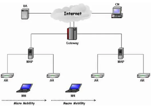
(11) Chapter 2 Background and Related Works In this chapter, we review the background knowledge and related works. First, we describe the important architectures in Mobile IP area such as Hierarchical Mobile IP and Fast handover protocol. Hierarchical Mobile IP with Fast handover is a major mechanism that reduces both the handoff delay and packet loss rate. Second, we address the handoff problems. Finally, we introduce authentication architectures such as RADIUS (Remote Access Dial-In User Service) and AAA (Accounting, Authentication and Authorization).. 2.1 Hierarchical Mobile IPv6 This architecture divides the problem into micro and macro mobility such as intra-domain mobility and inter-domain mobility. Hierarchical Mobile IPv6 [1] reduces the registration latency caused by long round trip delay between MN (Mobile Node) and HA (Home Agent) during handoff period.. Figure 2.1 Hierarchical Mobile IP Architecture. 3.
(12) 2.1.1 Protocol Description It is a well-known observation that MNs moving quickly away from their respective home domain will produce significant BU (Binding Update) signaling traffic and suffer from serious handoff latency and packet losses if no extension to the baseline Mobile IP protocol is used. Hierarchical Mobile IPv6 (HMIPv6) is a localized mobility management proposal that aims to reduce the signaling overhead due to user mobility, as shown in Figure 2.1. The mobility management inside the local domain is handled by a Mobility Anchor Point (MAP). Mobility between separate MAP domains is handled by MIPv6. The MAP basically acts as a local Home Agent. When a mobile node enters into a new MAP domain it registers with the new MAP to obtain a regional care-of address (RCoA) by performing regional registration. The RCoA is the address of current location that will be used by the mobile node to inform its Home Agent and correspondent nodes. Then, the packets will be sent to and intercepted by the MAP which acts as a proxy, and routed inside the domain to the on-link care-of address (LCoA). When a mobile node performs a handoff between two access routers within the same MAP domain, only the MAP has to be informed. So, after each movement between ARs (Access Routers) in the same domain, the MN needs to send a local registration to the MAP to update its localization into the domain LCoA (on-link care-of address). Thus, all MN movements within the domain are hidden from the home agent and correspondent nodes since the global care-of address of the MN does not change. However, this does not imply any change to the periodic BUs a MN has to send to HA, CNs and now additionally to the MAP. HMIPv6 features the following advantages: it includes a mechanism to reduce the signaling load in case of handoffs within the same domain, this may improve handoff performance by reducing handoff latency and packet losses because intra-domain handoffs are performed locally. However, since the periodic BUs will not be reduced 4.
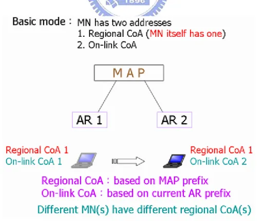
(13) except these due to handoffs, the gain will be depending on the frequency of mobile nodes changing their MAPs.. 2.1.2 Two Modes in HMIPv6 The mobility anchor point is announced in the agent advertisement messages sent by the AR in the domain. When an MN enters into a new domain for the first time, it must perform a home registration. Next, when it moves around within this domain, the MN can choose between basic mode and extended mode. In the former as shown in Figure 2.2, the MN has two addresses: a regional care-of address (RCoA) based on the MAP prefix and an on-link care-of address (LCoA) based on the current AR prefix. In this mode, the mobility anchor point acts as a home agent: it intercepts the packets destined to the regional care-of address and tunnels them to the corresponding on-link care-of address. These operations are totally transparent to the MN home agent, which does not need any modification.. Figure 2.2 Basic Mode in HMIPv6.. 5.
(14) Figure 2.3 Extended Mode in HMIPv6. However, not every MN can acquire an individual regional care-of address because of scalability or a network operator policy. In extended mode as shown in Figure 2.3, the regional care-of address is same as the mobility anchor point address. The mobility anchor point keeps a binding table with the current on-link care-of address of an MN matched with the MN home address. When it receives packets destined to an MN, it de-tunnels and re-tunnels them to the on-link care-of address (LCoA). This implies that each packet must contain the MN’s home address.. 2.2 Fast Handover Fast handover protocol [2] is based on layer 2 triggers to anticipate the L3 handovers. A mobile node can pre-register the new care-of address through the current access router by sending it to the new access router using fast handover protocol. The current access router can forward data packets destined to a MN to the new access router during handoff period. In this section, we describe details of fast handover protocol as follows. 6.
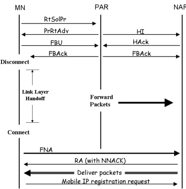
(15) 2.2.1 Overview The basic operations of the Fast handoff signaling are depicted in Figure 2.4.. Figure 2.4 Fast Handover Protocol Signaling.. In fast-handoff, the Previous Access Router (PAR) is defined as the router to which the MN is currently attached, and the New Access Router (NAR) as the router to which the MN is about to move to. The fast-handoff initiation is based on an indication from a wireless link-layer (L2) trigger, which shows that the MN will soon be handed off. Essentially, this indication mechanism anticipates the mobile node’s movement and performs packet forwarding accordingly. 7.
(16) 2.2.2 Protocol Description Fast-handoff schemes in MIPv6 introduce four additional message types for use between access routers and the mobile node. An access router here is defined as the last router between the wired network and the wireless network where the mobile node is situated. These four messages are: (1) Router Solicitation for Proxy (RtSolPr), (2) Proxy Router Advertisement (PrRtAdv), (3) Handover Initiation (HI) and (4) Handover Acknowledgement (HAck). To initiate a fast-handoff, the MN sends a RtSolPr message to the PAR indicating that it wishes to perform a fast-handoff to a new attachment point. The RtSolPr contains the attachment point link-layer address to indicate the new destination attachment. The mobile node will receive a PrRtAdv message from the PAR with a set of possible responses indicating that the point of attachment is i) unknown, ii) known but connected through the same access router or iii) is known and specifies the network prefix that the MN should use in forming the new CoA. Based on the response, the MN forms a new address. Subsequently, the MN sends a FBU(Fast Binding Update) using its newly formed CoA as the last message before the handover is executed. The MN then receives a FBack either through the PAR or the NAR indicating that the binding was successful. When the MN moves into the NAR’s domain, it sends the Fast Neighbor Advertisement, FNA, to initiate the flow of packets at the NAR. In addition to the message exchange with the MN, the PAR exchanges information with the NAR to facilitate the forwarding of packets among themselves and to reduce the latency perceived by the MN during the handoff. This is realized by the PAR sending a HI message to the NAR with the requested CoA (by either the PAR itself or the MN) on the NAR and the CoA being used currently at the PAR. In response, the PAR receives a HAck message from the NAR either accepting or 8.
(17) rejecting the new CoA. If the new CoA is accepted by the NAR, the PAR sets up a temporary tunnel to the new CoA. Otherwise the PAR tunnels packets destined for the MN to the old CoA, which will be temporarily hosted by the NAR. In either case, the PAR does not forward packets until it has received a BU from the MN.. 2.3 Handoff Latency Discussion In this section, we would like to discuss these factors which affect the handoff latency and the currently proposed methods to deal with this latency issue in wireless network environment.. 2.3.1 Latency Factors or Contributors The definition of the roaming latency is “The period from which the STA receives the last packet data from its old AP till which it receives packet data from the new AP, often referred to as the handoff latency or handoff delay”. There are many latency factors when a mobile node performs handover process. In the real situation, if a mobile device wants to access some network resources from the access router, it needs to go through a variety of processes such as scan, authentication, association, MIP signaling, and upper layer functions in order to sending or receiving data packets. We classify these functions by layers. Briefly, we could divide them into Layer 2 and Layer 3 functions. We will discuss the layer 2 factors and their processes first, and then the layer 3 functions and their handoff impact will be addressed.. Layer 2 Functions A mobile station needs three steps to complete the MAC connection to an access router or access point. Scan, authentication, and association are the main functions to connect to a new access point in layer 2. If the mobile station moves from an old. 9.
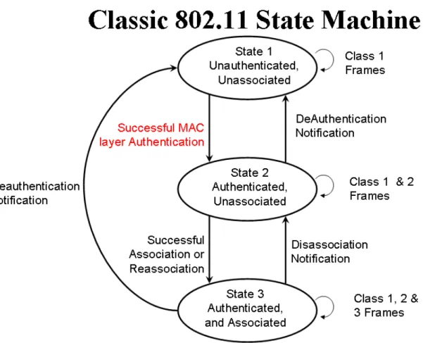
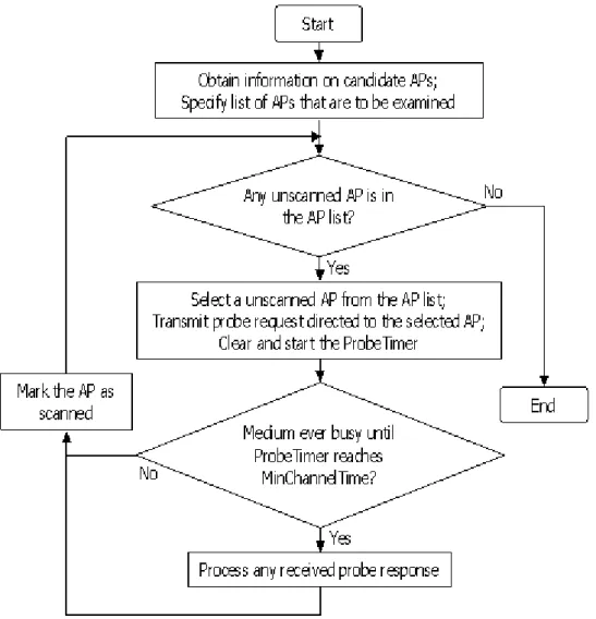
(18) access point to a new one, these three functions must be performed again. It costs a lot of time for scanning and authentication if security is under consideration. IEEE 802.11 defines the MAC process in a finite state machine as follows.. Figure 2.5 Classic 802.11 State Machine.. Figure 2.5 shows the operations and its state diagram in 802.11 Mac layer. There are two types of scan operations, passive and active. If a mobile device performs passive scan (beacon), the scan time will be depending on the beacon interval. It wastes much time waiting for a beacon to proceed to other actions. Active scan is better for a mobile station during handoff period because it can save 30 to 400ms comparing with passive scan [3]. So, many studies try to investigate how to reduce the scan time when a mobile device roams. In 802.11 wireless networks, access router 10.
(19) uses Open system or Shared-Key authentication methods to authenticate some mobile devices. Authentication function is to check the identity or key of mobile device. Classic 802.11 authentication mechanism has some drawbacks because the mobile device always uses the same pre-shared key which is statically configured, to communicate with the access router, thus it needs some methods to compensate its deficiency. The time to trigger roaming is the key point, and basically we should use some message to reduce or to optimize the scan and authentication time during the handoff period.. Layer 3 Functions A mobile client would like to use the same address such as home address to travel everywhere without having to change the address. However, a mobile node must send a notification to its home agent regarding its current location when it is visiting a foreign domain. This action is called “Mobile IP registration”, which allows a mobile node to continuously receive data packets without manual address change. This can be done by using a care-of address. An access router needs to perform DAD (Duplicate Address Detection) to check whether the assigned care-of address is correct or not. DAD operation also affects the handoff latency because it costs much longer time, say, about 3000ms. MIP registration and DAD will increase handoff delay and packet loss. Existing studies don’t take the authentication time into consideration under this architecture. If we add an authentication mechanism, it will increase the total handoff latency as well as packet loss rate. There are some other latency factors such as IKE renegotiation and TCP adjustment. The problems regarding how can we reduce the impact of packet losses and handoff delay time among these topics will be discussed in the following.. 11.
(20) 2.3.2 Proposed Methods for Solving These Factors In previous section we described some latency factors and reasons that cause the latency. In this section, we briefly introduce some proposed methods which reduce the problems mentioned in the previous section.. Layer 2 Algorithm (1) Scan There are various proposed solutions discussing about this. Since channel scanning is a time-consuming process, Fast Active Scan is proposed to reduce the scanning time. The main algorithm is as shown in Figure 2.6.. Figure 2.6 Fast Active Scan Algorithm. 12.
(21) This method improves the MinChannelTime and MaxChannelTime to optimize the scanning time or to reduce the unnecessary latency. Figure 2.7 shows the result of the fast active scan. Another method that reduces scanning time is “Selective Scanning” [4], which selects the channel to scan by cache and mask instead of full scan.. Figure 2.7 Fast Active Scan Time.. Regarding the other methods which reduce the handoff latency, first, a mobile node can use the information of RSS (Received Signal Strength) to pre-trigger the handoff. The key point is when a mobile node decides to roam to another domain. You can use any information from MAC layer or else to tell the mobile node to trigger handoff early. Second, some papers construct movement patterns [5] or models to predict the mobile node’s next position in the future according to the probability or statistics. Here, we describe the weakness of authentication in MAC layer. (2) Authentication Authentication delay can be reduced by FHR [6] [7]. Frequent Handoff Region (FHR) can be configured statically with administrator or dynamically with neighbor selection algorithm. Authentication procedure of MAC layer protocol is not secure in. 13.
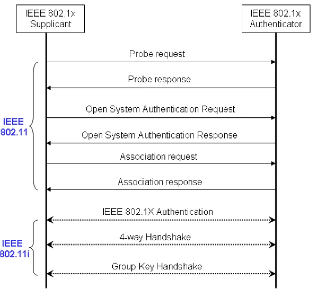
(22) IEEE 802.11 standard. So, IEEE 802.1x [8] is proposed to enhance authentication mechanism in MAC layer. But it costs more than 1200ms to complete the authentication process, the latency time will increase quickly. Although 802.1x can improve the security in MAC layer, it causes a significant delay during handoff. We show the IEEE 802.1X flow in MAC operations as in Figure 2.8.. Figure 2.8 IEEE 802.1x in MAC Layer.. There is a problem by using IEEE 802.1x of MAC layer in Mobile IP. In the original structure of Mobile IP, it causes 3 seconds to complete the handoff. If we use IEEE 802.1x to make MAC layer more secure, the handoff time will be larger than 3 14.
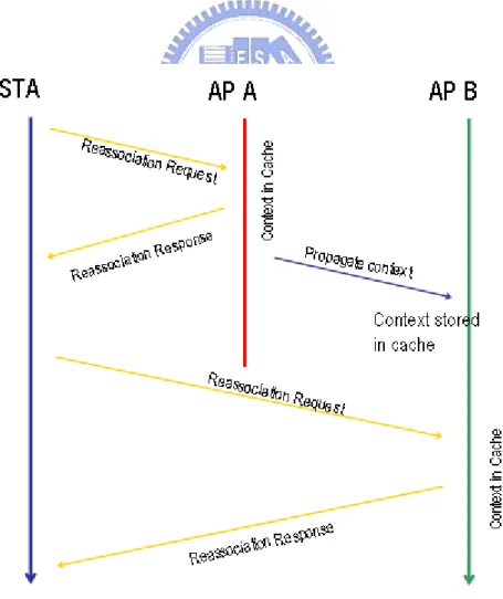
(23) seconds, it is a significant delay during authentication process. Also, the handoff time reduced through other means will be increased due to the IEEE 802.1x authentication process. IEEE 802.1x authentication time should be reduced in order to providing the high quality Multimedia Streaming and VOIP services. To achieve the goal, transient authentication or pre re-authentication is essential. (3) Association: A typical solution for reducing the association delay is IAPP [9]. IAPP can provide a smooth handoff for roaming devices. Its main idea is to transfer contents from the old AP to the new AP, but it increases the handoff latencies drastically. IAPP with caching can provide a better performance for handoff latency than IAPP. Figure 2.9 shows the IAPP with Caching.. Figure 2.9 Message Flow of IAPP with Caching. 15.
(24) Layer 3 Algorithm Handoff latency consists of address (re)configuration, registration and processing delay. Packet buffering is a general mechanism for reducing the handoff latency and packet loss rate. We can increase the buffer size to buffer more data packets destined for a MN to reduce the packet loss rate. Since buffer size is limited, we can drop some low priority packets to provide a higher quality of service or maintain two buffers located in PAR or NAR to alleviate the impact [10]. Also, some approaches use multicast [11] or neighbor-cast [12] to send data packets in order to reduce the packet loss rate. This method wastes lots of network resources, but it is a robust approach to solve the problem. Fast handover with Hierarchical Mobile IP is a good method for reducing the registration latency and address reconfiguration as mentioned in Section 2.1 and 2.2. Fast handover protocol is to perform a L3 handoff before executing L2 handoff for providing low latency handoff based on information from L2 trigger. It is a pre-registration [13] [14] method. Also, there is a post-registration [13] [14] method to reduce the handoff latency. A MN first completes L2 handoff, then it continues to receive data packets by using the old FA and CoA through bi-directional tunnel between the old FA and new FA. Robert Hsieh proposed a new architecture called S-MIP [15] to lower the latency during handoff period by decision engine successfully. But it is a centralized mechanism and it requires extra signaling and imposes a bound on the speed of MNs. We can use some information of MAC layer to early forward packets toward NAR before handoff. Regarding AR(s) to be chosen, there are many policies such as L3-FHR algorithm to select a better AR or AR(s). To attack the handoff latency problem the current state of research topics are listed as follows. 16.
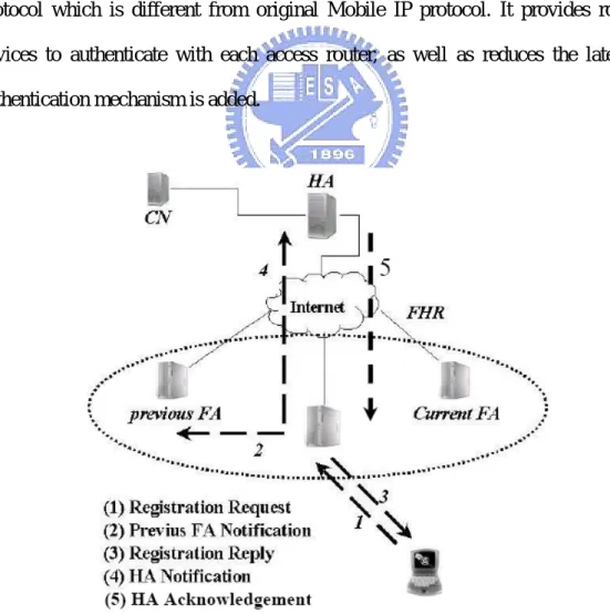
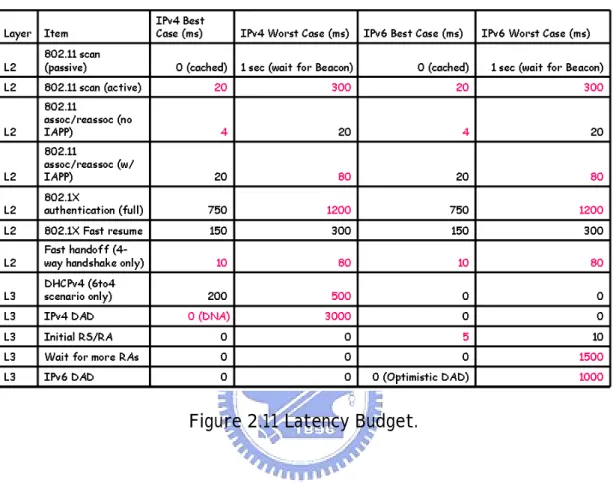
(25) (1) Dynamic Hierarchical re-arrangement, (2) Seamless Handover with strategic buffering, (3) Multicast Hierarchical Mobile IP handoff, (4) Movement prediction, (5) Movement pattern detection, (6) Advanced Reservation of resources, (7) Measurement-based resource reservation, (8) Policy-based Handoff.. Mobile IP Fast authentication protocol [16] [17] is a brand new signaling protocol which is different from original Mobile IP protocol. It provides roaming devices to authenticate with each access router, as well as reduces the latency if authentication mechanism is added.. Figure 2.10 Mobile IP Fast Authentication Protocol.. 17.
(26) RADIUS and AAA/Mobile IP focus on user authentication. We have a detail description of these methods in the next section. Here, we list some latency budget as in Figure 2.11. These values shown below are for reference.. Figure 2.11 Latency Budget.. If we want to lower the impact on TCP traffic, the disconnection time should be smaller than the RTO (Retransmission TimeOut) value to avoid the retransmission of data. This problem is a key issue no matter the authentication is used or not.. 2.4 Authentication Mechanism There are quite a few proposed authentication mechanisms and architectures in wireless networks such as IEEE 802.1x, AAA/Mobile IP and Mobile IP Fast authentication. We divide these authentication methods into two categories: (1) Layer 2 authentication and (2) Layer 3 authentication. IEEE 802.1x adopts EAP (Extensible Authentication Protocol) and RADIUS (Remote Authentication Dial-In User Service). 18.
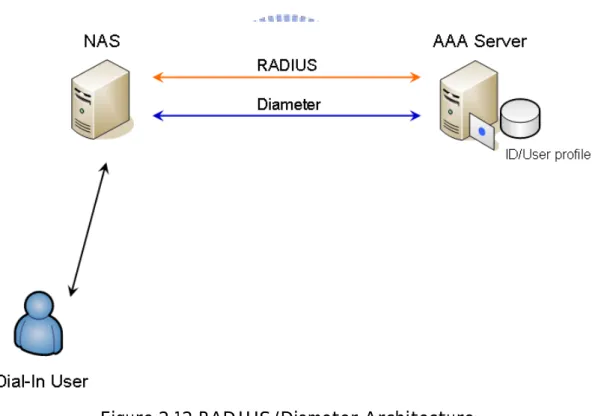
(27) to provide authentication for wireless stations. In other words, it is a Layer 2 authentication approach because it uses a newly defined MAC frame to perform authentication through EAPOL. In this thesis, we focus on Layer 3, or user authentication mechanism.. 2.4.1 RADIUS RADIUS [18] technology was originally developed to manage dial-in access to the Internet. It is now being leveraged to manage access control for other applications and other access methods. It is an efficient protocol that manages a single database containing authentication (user name and credentials) access policy and provisioning information.. Figure 2.12 RADIUS/Diameter Architecture. Figure 2.12 shows the relationship between a Dial-In User and the AAA Server. Here NAS operates as a client of RADIUS, which is responsible for user authentication and returns all configuration information to the user. A dial-in user should send some information to Network Access Server (NAS). While AAA Server. 19.
(28) (RADIUS Server) uses RADIUS or Diameter communication protocol to authenticate dial-in user’s information sent through NAS. It replies the authentication result to NAS, and NAS judges dial-in user’s access right to the Internet. Next, we show the detail messages of RADIUS and Mobile IP.. Figure 2.13 RADIUS & Mobile IP Message Flow. There are nine messages communicated between a user and RADIUS server through NAS. RADIUS separates these operations independent of Mobile IP messages. Two phases operation is so slow and inefficient. If AAA operations consume a lot of time to work, connections of mobile node may be interrupted. So, a new protocol called Diameter is proposed. The original suggestion was to call it RADIUS v2, this protocol supports the mobility and it provides a reliable transport of TCP or SCTP rather than UDP. In the next section, we discuss AAA/Mobile IP by using Diameter MIP.. 2.4.2 AAA/Mobile IP There are two models in AAA/Mobile IP [19][20]. One is the basic model, the 20.
(29) other is the broker model. The first one is a basic model as shown in Figure 2.14. A mobile Node sends registration requests to AAAF through attendant, and AAAF will consult AAAH through security association. But there is a problem, AAAF and AAAH may be far away, thus messages exchanged between them in different domain will cause significant latency during authentication.. Figure 2.14 AAA/Mobile IP Basic Model.. The broker model needs another component called AAAB server, the function of AAAB server is a common trust agent between AAAF and AAAH, which don’t have direct trust relationship, hence we need AAAB. AAAB server is an intermediate server, so this model will cause the latency of message exchange larger than that of basic model.. Figure 2.15 AAA/Mobile IP Broker Model.. 21.
(30) Finally, we describe the detail message flow of AAA/Mobile IP as in Figure 2.16. In the original structure of Mobile IP, a mobile node just sends out the registration request and waits for reply from FA/HA. But now, mobile nodes have to wait an extra time period for authentication process. There are some serious problems during handoff if the authentication time increases to a certain amount.. Figure 2.16 AAA/Mobile IP Message Flow.. 22.
(31) Chapter 3 Proposed Approach In this chapter, we propose a two-stage authentication scheme such as transient authentication and user (re) authentication mechanism. First, we describe AAA/Mobile IP in our architecture. Next, we describe the user authentication and transient authentication mechanism in detail. The modification of proposed method in NS-2 and other comments are illustrated in last sections.. 3.1 AAA/Mobile IP in Our Architecture AAA/Mobile IP is introduced in Chapter 2. We use AAA/Mobile IP to authenticate a MN and get the certificate from MAP during registration simultaneously. This certificate signed by MAP can be used in the same MAP domain to get the different local certificate from different access routers for passing the filtering rule of MN. First, we show the authentication message flow in AAA/Mobile IP as shown in Figure 3.1. A mobile node sends its NAI in registration request and AAAF forwards registration message with authentication information to AAAH. Then, AAAH generates 3 keys to communicate with the MN and FA and sends them in registration reply message. After registration process, MN derives 2 keys such as MN-FA and MN-HA keys to encrypt data on the Internet. We use this characteristic in our Hierarchical Mobile IP with Fast handover experiment. If mobile node first enters into the new Hierarchical Mobile IP domain, it will perform AAA/Mobile IP initial registration and regional registration. When MAP receives the initial registration reply from HA, it checks the information in this message and adds an extra certificate signed by MAP called CAmap on registration reply message to the MN. Then, the. 23.
(32) access routers under MAP can authenticate the MN through CAmap and send out a new local certificate signed by the access router.. Figure 3.1 AAA/Mobile IP Initial Registration.. Figure 3.2 shows the GK and CAmap distribution during AAA/Mobile initial registration. After initial registration, MN derives two keys from HA (AAAH), one key (GK) from MAP and one key (KPAR) from current access router. The group key is used to encrypt packets for transmission in the MAP domain. The other key distributed by an access router is used to encrypt packets between mobile node and access router. This is the last mile key. A mobile node will use these two keys to transmit some information to new access router through current access router based on fast handover control messages, this action is called transient authentication. We describe this content in later sections. 24.
(33) Figure 3.2 CAmap & GK & KeyPAR Distribution Flow.. 3.2 Two-Stage Authentication Scheme 3.2.1 User Authentication (Re-authentication) There are several approaches that filter packets toward mobile node as follows. MAC filtering is a common method to drop the illegal MAC address packets of mobile node. A switch or router would construct a table to record which node passes the authentication. Currently, the most popular user authentication is the web-based approach. A mobile user just inputs the correct password to the web interface and sends it to the authentication server to open the access right for himself/herself. Then, the mobile user can get the access right to the Internet. The re authentication we propose is to use certificate to derive the access right to the Internet. Also, each access router can identify the certificate of MAP and sign it for the mobile user. Access routers use their own certificate to authenticate the mobile user and to pass the packets over to the mobile node.. 25.
(34) Four-way Re-authentication Figure 3.3 shows the 4-way handshaking of the re (user) authentication.. Figure 3.3 4-way Re-authentication. We define a 4-way re-authentication signaling to simulate user authentication process similar to AAA operations. If a mobile node doesn’t have a certificate of access router, it can send certificate of MAP to derive a certificate of the access router, which can authenticate mobile node by identifying CAmap. An access router signs a local certificate of its own to a mobile node for accessing the Internet under its coverage. When an access router receives the correct local certificate, it will stop dropping the packets destined to the mobile node, shown as the third message in Figure3.3. Also, we use challenge/response to identify each other against the reply attack during transmission. Currently, there are two authentication modes, unilateral client authentication and mutual authentication. The former is that the client digitally signs a challenge from the server, thus authenticating the client to the server. Mutual authentication is that the client digitally signs a challenge produced by the server and the server digitally signs a challenge produced by the client. Thus both the client and. 26.
(35) server authenticate each other. So, we adopt the mutual authentication mode, as Figure 3.3 shows. First, a mobile node sends its R1MN random number to the access router. Then, the access router replies with R1NAR (PAR) and R1MN random numbers. The MN receives these random numbers and check whether they are correct. Moreover, the mobile node also replies with R1NAR (PAR) and a new random number R2MN. The access router checks this random number to identify whether the message is freshness. After first three steps, they can identify each other and complete the authentication process. Through this 4-way re (user) authentication, the access router records the information of the mobile node and passes the packets to it. Packets destined to the mobile node are dropped by access router if the destination address is not be authenticated. An access router needs to maintain a table for authenticated users and a timer for refreshing the entry if it expires. The access router decides to drop or forward this packet according to the existence of destination address of the packet in the table. We can see that our simulation 4-way signaling is similar to IEEE 802.1x re-authentication messages from Figure 3.4. So, we use this method to simulate the authentication delay during handoff.. Co-work with IEEE 802.1x Re-authentication User authentication can be replaced by other user authentication protocols such as IEEE 802.1x. Transient authentication also can co-work with IEEE 802.1x user authentication scheme. So, the two-stage authentication is transient and IEEE 802.1x processes. If IEEE 802.1x supports transient authentication, it needs to open the controlled port for the mobile node temporarily to receive data according to the authentication table. If the lifetime for transient authentication expires, the authenticator will check if the IEEE 802.1x state is authenticated. If IEEE 802.1x state is not authenticated and lifetime for transient authentication expires, the authenticator 27.
(36) will close the controlled port until IEEE 802.1x state is authenticated. Figure 3.4 shows the IEEE 802.1x state transition in roaming [8].. Figure 3.4 Re-authentication State Transition in Roaming.. 3.2.2 Transient Authentication There are several approaches to reduce handoff time, as discussed in Chapter 2. We choose the Hierarchical Mobile IP with fast handover as our baseline architecture, because it features the lowest handoff time among all available approaches. We can add an extra authentication signaling to increase a little handoff time; then we can also provide authentication function. Otherwise, it may cause a significant delay due to the original large handoff time. The scenario for handover is illustrated in Figure 3.5. The mobile node first enters into the hierarchical structure, and it performs Mobile IP registration, Regional registration and re authentication. When the mobile node roams to NAR, it performs regional registration and re (user) authentication. A MN needs to spend some time doing authentication before receiving packets. Whether the time is 28.
(37) long or short depends on the complexity of authentication. If the mobile device often roams between access routers, we should try to reduce the authentication time by transient authentication. We observe the control message of fast handover protocol and try to modify it for providing a transient authentication function. Our main objective is to derive a temporary access right of new domain through fast handover signaling. Also, we try to get a new local certificate of NAR through fast handover control messages. So, the new access router not only pre-registers new care-of address of mobile node but also temporarily authenticates mobile node through these control signaling. It can reduce handoff and authentication delay through this method.. Figure 3.5 Scenario for Handover. 29.
(38) Figure 3.6 shows a scenario of transient authentication between access points. We adopt the similar concept to perform our transient authentication in fast handover signaling. From Figure 3.6, there is a pre-existing secure connection between oAP and nAP. This pre-existing connection is to ensure transmission between them safe.. Figure 3.6 Transient Authentication Scenario between APs.. Our architecture is similar to Figure3.6. A mobile node in old domain performs AAA/Mobile IP to authenticate itself by AAAH, to derive keys and to get the certificate of MAP. When the mobile node detects its fading RSS (Received Signal Strength) from current AP, it will trigger fast handoff before L2 handoff. The MN adds some authentication information into fast handover messages and sends them to PAR. Then, PAR adds its information and forwards these messages to NAR in pre-existing secure connection. NAR checks information in these messages and replies result to the mobile node through PAR in secure connection, finally PAR will forward this message to the mobile node. After these steps, the mobile node completes its transient authentication process. Next, we show the message flow and explain the details.. 30.
(39) Figure 3.7 Transient Authentication Messages & Fast Handover Signaling.. Figure 3.7 shows the total message flow in detail. We list extra information in RtSolPr, HI, HAck, PrRtAdv, and FNA for transient authentication as follows. RtSolPr: {Ek MN −GK {CAMAP || CR || HIPMN || TMN }, MAC MN , RMN }Ek MN − PAR CR = H 1 (GK , MAC MN , NewCoA, TMN ). GK: Group Key. RtSolPr contains credential CR generated by the roaming MN and a certificate of MAP identified by NAR. HIPMN and MACMN are stored in authentication table of NAR. Other information is for challenge/response. These values are encrypted by keys. HI: {Ek MN −GK {CAMAP || CR || HIPMN || TMN }, MAC MN , RPAR } PAR adds its challenge random number to identify the NAR for later use. HI contains information from RtSolPr and random number of PAR. This message is transmitted through existed security association. 31.
(40) HAck: {Ek MN −GK {TMN || CR ' || R NAR }, RPAR } CR’: Expire time for CR When NAR receives the HI message, it checks the new care-of address of the mobile node and decides to register if it is allowed. NAR extracts the information of HI, then it checks the CAmap to authenticate the mobile node. Finally, NAR creates a new entry for the mobile node and records a temporary certificate called CR. At this time, the packets destined to MN through NAR will be forwarded because of its temporary authentication.. NAR gives this entry a lifetime and passes the authentication of MN. for a short period of time. This entry will be deleted if it expires. The lifetime is refreshed by receiving a correct CR sent by MN. Packets toward MN through NAR are dropped if this entry expires or it does not exist. So, HAck contains the lifetime of CR and a random number generated by NAR for later use. This message is transmitted to PAR in the secure association between PAR and NAR. PrRtAdv: {Ek MN −GK {TMN || CR ' || R NAR }, RMN }Ek MN − PAR PAR receives the HAck message and checks the RPAR to identify NAR against replay attack. Then, it sends a PrRtAdv message to the MN. PrRtAdv contains the information generated by NAR. Two important values are CR’ and RNAR. This message is encrypted by keys. The MN stores these two values for later use. FNA: Ek MN −GK {R NAR || CR || HIPMN } After layer2 handoff, the mobile node will send a FNA to NAR for receiving data packets. The MN sends RNAR and CR to NAR. RNAR is for challenge/response and CR is for extending the entry lifetime of mobile node in the authentication table of NAR. Then, MN performs re authentication after MIP/MAP registrations by sending the correct certificate CAmap. At this time, it needs 2-way handshaking to complete the re authentication because its correct certificate was derived from NAR previously. NAR operations upon receiving a FNA are shown in Figure 3.8.. 32.
(41) Figure 3.8 NAR Operations. When NAR receives the FNA message, it extracts the RNAR and CR to check whether they are correct or not. If values are correct, it extends the entry lifetime. If the authentication is failed, packets toward the MN are dropped. The mobile node can derive a buffer time to receive data packets quickly through transient authentication. Figure 3.9 shows the message flow of transient authentication.. Figure 3.9 Scenario of Transient Authentication Message Flow.. 33.
(42) 3.3 Comparison There is another authentication scheme called L3-FHR [6]. The main idea is to broadcast authentication reply packets to all L3-FHR APs. So, MN can re-authenticate with new target AP without authenticating with home AAA server again. It may reduce the re-authentication time. New target AP will stop dropping packets after MN completes the re-authentication. Its message flow is shown on left-side in Figure 3.9. We put our proposed scheme on right-side in Figure 3.9 to show the difference.. Figure 3.10 L3-FHR & Two-Stage Message Flow.. Then, we use a table to list the difference between these two schemes in detail, as shown in Figure 3.10. Both these two schemes are to pre-send the authentication information to the new target AP before handoff. But the two-stage scheme not only 34.
(43) pre-sends this authentication information but also registers its authentication information temporarily with new target AP before L2 handoff. It can stop dropping packets on new target AP temporarily. In other words, L3-FHR AP will drop packets if MN doesn’t complete the re-authentication process. L3-FHR duplicates authentication packets to all L3-FHR APs, but our two-stage scheme sends authentication packets through fast handover signaling. The following are the main differences.. Figure 3.11 L3-FHR & Two-Stage Comparisons.. 35.
(44) 3.4 Contributions We list the contribution of two-stage authentication scheme as follows. Two-stage authentication Early to derive the access right in the new domain Perform transient authentication before L2 handoff Fast handover signaling piggybacks these authentication information No protocol overhead Simple and feasible implementation Reduce original IEEE 802.11 authentication procedure time Early to send “identity” to new BS (AP) Main factors affecting packet loss rate Authentication processing time (100ms v.s 300ms) UDP Packet loss rate 100ms & 1Mbps 41.6% (no-transient). 13.6% (transient). 300ms & 1Mbps 100% (no-transient). 34.4% (transient). UDP data sending rate (100Kbps v.s 1Mbps) UDP Packet loss rate 32% (100kbps & no-transient). 8% (100kbps & transient). 41.6% (1Mbps & no-transient). 13.6% (1Mbps & transient). More efficient than L3-FHR authentication scheme Just send authentication information to only one target AP instead of all L3-FHR APs.. 36.
(45) 3.5 NS-2 Modification We use NS-2.1b7a to simulate our proposed method. This original version doesn’t support HMIP and Fast handover functions. We adopt ns2-extension written by Robert Hsieh to construct our basic environment. We list the modified parts as follows. Hack source codes & Patch them to support HMIP and Fast handover Mobile IP Registration Add some information into registration request before it is sent by an MN. MAP Registration and Authentication in one request to HA. Sign CAMAP and Group Key into registration reply message. PAR Add its KPAR to registration in reply message. Re (user) Authentication Authentication messages & its processing delay time Maintain new authentication tables distributed in ARs. Each table records authentication information and status of MN. Maintain a timer to refresh its table entry. Check whether the packet is illegal or legal. Drop or forward this packet to MN Sign new certificate and identify CAMAP. Transient authentication Add authentication information into Fast handover control messages. Generate and register the temporary certificate (CR) with NAR Check CR in FNA. 37.
(46) 3.6 Comments Many authentication methods are proposed in different goals. Some focus on layer 2 authentication and the others focus on upper layers. Each layer may have its authentication function. A mobile node needs to perform many authentication procedures in each layer if we want to have a secure communication. Generally, the MN needs to perform layer 2 and user authentication when it roams. Currently, IEEE 802.1x is a layer 2 authentication method, it takes approximately 1200ms or longer to complete total steps. If a mobile node supports this function with Mobile IP, it may cause some problems. Figure 3.12 shows the message flow with IEEE 802.11, IEEE 802.11i and Mobile IP.. Figure 3.12 Handoff Procedure with IEEE 802.11 & IEEE 802.11i & MIP. 38.
(47) A mobile node in foreign domain needs to register with home agent periodically before its lifetime expires. If layer 2 authentication processing time is longer than registration lifetime, the home agent begins to drop packets destined to MN. But a mobile node needs to complete layer 2 and layer 3 handoffs when it roams, this takes much longer time to finish these operations excluding authentication processes. Mobile IP registration lifetime would be increased if we add authentication functions. This is a tradeoff between fast handoff and secure authentication. So, transient authentication is an essential component if authentication is used during handoff.. 39.
(48) Chapter 4 Performance Evaluation In this chapter, we verify the proposed method and evaluate the performance as mentioned in Chapter 3 by using ns-2 network simulator version 2.1b7a. First, we describe our simulation environment and configuration. Then, we show the results of our proposed method and analyze its performance.. 4.1 Simulation Environment and Configuration In order to verify the performance of the transient authentication mechanism proposed in Chapter 3, we use ns-2 distribution version ns-allinone-2.1b7a patched with two available modules, NO Ad-Hoc Routing Agent (NOAH) [21] and HMIPv6 with Fast-handover (FHMIP) [22]. We add some extra features and modify some codes based on these modules, including re (user) authentication mechanism and transient authentication with fast handover protocol described in Chapter 3. We build up the network topology to evaluate the proposed mechanism as shown in Figure 4.1. There are nine nodes in the network topology, including Correspondent Node (CN), Home Agent (HA), Mobility Anchor Point (MAP), Previous Access Router (PAR), New Access Router (NAR), Mobile Node (MN), and three fixed nodes. The bandwidth (Megabits/second) and link delay (milliseconds) are shown on the link between two nodes. The distance between two access routers is 70 meters and each router advertisement interval is one per second [23]. The wireless coverage area of the access router is approximately 100 meters in radius. We set up the handoff delay to 20ms in our simulation. The mobile node starts to move from PAR to NAR with speed 1 meter per second at the 10th second. The total simulation period is 80. 40.
(49) seconds.. Figure 4.1 Network Topology for Simulation.. We evaluate three experiments in this topology. First, A TCP sender (CN) starts to send packets at 5s until the end of the simulation and we would like to observe its variance when using FTP service. Second, A UDP sender (CN) starts to send packets at 5s until the end of the simulation. Also, we could observe the different impacts 41.
(50) between UDP and TCP packets. Finally, we want to know how the authentication time affects the performance when it increases. We set the L2 handoff time to 20ms. The default time value of sending authentication information by either the sender or receiver is 100ms. We adjust this value to observe the variance in different processing time.. 4.2 Simulation Result and Analysis In our experiments, we want to show two different cases during handoff period. One is the fast handoff and user authentication without transient authentication, and the other is the same except with transient authentication mechanism. We compare the results for both cases. The total fast handover takes approximately 100ms to complete.. 4.2.1 TCP Experiment First, we see the different handoff time between original Mobile IP and HMIPv6 with Fast handover, as shown in Figure 4.2. The original flat Mobile IP takes approximately 4 seconds to perform the handoff from 50 to 54 sec. This time is too long so it interrupts the TCP connection between CN and MN, hence it can’t provide good services such as Multimedia streaming or VOIP. HMIPv6 with Fast handover encounters handoff at 40.6 sec and it takes 100ms to continue the reception of the packets from new access router at 40.7sec. So, this handoff time is better for providing Multimedia streaming or VOIP service. Based on this advantage of Fast handover, we try to add an extra authentication mechanism on it. If authentication mechanism is added to the fast handover mechanism, we should control the overhead time in 50ms. Next, we show three cases under fast handover, including original fast handover, fast handover without transient authentication, and fast handover with. 42.
(51) transient authentication. These three cases feature differences on handoff as shown in Figure 4.3. 9400 9100. MN Recv TCP Sequence Number. 8800 8500 8200 7900 7600 7300 7000 6700 6400. orig-fhmip orig-flat. 6100 5800 5500 40. 41. 42. 43. 44. 45. 46. 47. 48. 49. 50. 51. 52. 53. 54. 55. 56. 57. 58. Time (seconds). Figure 4.2 FHMIP and Flat Mobile IP without Authentication.. 7000. MN Recv TCP Sequence Number. 6900 6800 6700 6600 6500 6400 6300. transient no-transient no-auth. 6200 6100 6000 40. 40.5. 41. 41.5. 42. 42.5. 43. 43.5. 44. 44.5. 45. Time (seconds). Figure 4.3 Original & with & without Transient Auth. under Fast Handover.. 43.
(52) We know that transient authentication reduces the handoff time, this is same as original structure under fast handover as shown in Figure 4.3. Also, the data curve for fast handover with transient authentication is almost the same as fast handover without extra authentication mechanism, this result matches our expectation. 7000. MN Recv TCP Sequence Number. 6900 6800 6700 6600 6500 6400 6300 6200. transient no-transient. 6100 6000 40. 40.5. 41. 41.5. 42. 42.5. 43. 43.5. 44. 44.5. 45. Time (seconds). Figure 4.4 Authentication Processing Time 100ms.. The mobile node can’t receive any data packets from 40.51 second to 41.14 second during fast handoff and re (user) authentication as shown in Figure 4.4. It takes a mobile node 630ms penalty for continuing to receive the data packets destined for itself. The time penalty may break the TCP connection if the delay increases. The delay time causes the mobile node to defer the reception of data packets. The new Access Router drops 22 data packets destined for the MN during authentication period, and 8 data packets are lost during fast handoff period. So, the total lost packets toward the mobile node are 30 data packets. In this experiment, we set the L2 handoff time value to 20ms. If we add more delay time, more packets will be dropped, these data packets dropped due to handoff and authentication will be retransmitted by the 44.
(53) correspondent node. Performing transient authentication mechanism could decrease the packet loss rate during the authentication process as shown in Figure 4.4. Transient authentication mechanism can alleviate the delay time as well, this allows a mobile node to receive data packets earlier. Transient authentication mechanism offers a buffering time for a mobile node to pass temporary authentication and receive data packets quickly. Also, the mobile node uses temporary certificate to extend the authentication time not to expire when the mobile node doesn’t complete the re (user) authentication. So, no data packets will be dropped during authentication process. The mobile node gets a temporary access right to keep receiving data packets in the new domain such as NAR. Compared with the scheme without transient authentication as shown in Figure 4.4, formal authentication indeed increases or enlarges the delay time and packet loss rate. If we perform transient authentication prior to handoff, the performance will be improved. Next, we show the growth of lost packets if we increase the authentication process time. 7000 6950 6900. MN Recv TCP Sequence Number. 6850 6800 6750 6700 6650 6600 6550 6500 6450 6400 6350 6300 6250 6200. transient no-transient. 6150 6100 6050 6000 40. 40.5. 41. 41.5. 42. 42.5. 43. 43.5. 44. 44.5. 45. 45.5. 46. 46.5. Time (seconds). Figure 4.5 Authentication Processing Time 200ms. 45. 47. 47.5. 48.
(54) 7000 6950 6900. MN Recv TCP Sequence Number. 6850 6800 6750 6700 6650 6600 6550 6500 6450 6400 6350 6300 6250 6200. transient no-transient. 6150 6100 6050 6000 40. 40.5. 41. 41.5. 42. 42.5. 43. 43.5. 44. 44.5. 45. 45.5. 46. 46.5. 47. 47.5. 48. Time (seconds). Figure 4.6 Authentication Processing Time 300ms.. The delay of receiving packets is indeed higher depends on processing time as shown in Figure 4.4, 4.5 and 4.6. We combine three different cases including with and without transient authentication into two graphs shown below. The authentication processing time is 100ms, 200ms and 300ms, so the total completion time is 330ms, 700ms and 1sec respectively, as shown in Figure 4.8.. Authentication processing time. Number of lost packets. 100 ms. 30. 200 ms. 31. 300 ms. 32. Table 4.1 Authentication Processing Time & Lost Packets Relationship.. We can observe that the number of lost TCP packets increases slowly if we increase authentication processing time quickly. This result is due to TCP sliding 46.
(55) window effect. The mobile node can’t receive the packets dropped by Access Point if it doesn’t authenticate with that Access Point. Therefore, the sender can’t receive the ACKs from receiver. The packets of offered window may be dropped by Access Point due to authentication mechanism. Figure 4.7 shows the TCP sliding window.. Figure 4.7 TCP Sliding Window.. Sender will retransmit the first packet of offered window if the packets of usable window are sent and the sender doesn’t receive any ACKs from receiver. The authentication processing time increases the delay for the mobile node to receive the packets and it may interrupt the TCP connections between the CN and the MN. 7000 6950 6900. MN Recv TCP Sequence Number. 6850 6800 6750 6700 6650 6600 6550 6500 6450 6400 6350 6300 6250. 100ms-no_transient 200ms-no_transient 300ms-no_transient. 6200 6150 6100 6050 6000 40. 40.5. 41. 41.5. 42. 42.5. 43. 43.5. 44. 44.5. 45. 45.5. 46. 46.5. 47. 47.5. Time (seconds). Figure 4.8 100ms – 300ms Cases without Transient Authentication. 47. 48.
(56) 7000 6950 6900. MN Recv TCP Sequence Number. 6850 6800 6750 6700 6650 6600 6550 6500 6450 6400 6350 6300 6250. 100ms-transient 200ms-transient 300ms-transient. 6200 6150 6100 6050 6000 40. 40.5. 41. 41.5. 42. 42.5. 43. 43.5. 44. 44.5. 45. Time (seconds). Figure 4.9 100ms – 300ms Cases with Transient Authentication.. 4.2.2 UDP Experiment We can observe the performance on TCP as mentioned above. Now we change the service to UDP, the result is presented as follows. We set the UDP related traffic value in the following: $cbr set type_ CBR $cbr set packet_size_ 1000 $cbr set rate_ 1mb $cbr set random_ false. We will discuss and compare the effect of various data rates on UDP services. UDP service is different from TCP service because it is a connectionless service, so the lost UDP packets will not be retransmitted again. If the packet loss rate is high, there will be a noticeable gap, as shown in the following figures.. 48.
(57) 4600 4580. MN Recv UDP Sequence Number. 4560 4540. no-auth & no-transient & transient. 4520 4500 4480. no-auth. 4460 transient. 4440 4420 4400. no-auth no-transient transient. 4380 no-transient & transient. 4360 4340 4320 4300 40. 40.2. 40.4. 40.6. 40.8. 41. 41.2. 41.4. 41.6. 41.8. 42. Time (seconds). Figure4.10 Original & with & without Transient Auth. under Fast Handover. Figure 4.10 shows the difference between three cases under UDP services. We could observe that the transient authentication curve is similar to the original fast handover. So, the packet loss rate is almost equal, while the packet loss rate of fast handover without transient authentication is high. 600 580. UDP Sequence Number. 560 540 520 500 480 (40.589763, 444). 460. (41.069763, 450). 440. no-transient transient. (40.429763, 442). 420 400 40. 40.5. 41. 41.5. 42. 42.5. 43. 43.5. 44. 44.5. 45. 45.5. 46. 46.5. 47. 47.5. Time (seconds). Figure 4.11 UDP with 100Kbps Data Rate. 49. 48. 48.5. 49. 49.5. 50.
(58) no-transient timestamp. no-transient udp seqno. 40.429763. 442. 41.069763. 450. Table 4.2 No-transient with UDP 100Kbps during Handoff. In order to analyze the UDP packet loss rate, we add a sequence number to each packet to observe the growth of packet loss. First, we set the UDP data rate to 100kbps as shown in Figure 4.11, and there are 8 lost packets during re (user) authentication without transient authentication in 640ms. This elapsed time is too large to offer a good Multimedia Streaming or VOIP service. Actually, when users of a multimedia streaming application move from the coverage area of an AP (access point) to the other, the connection must be handed off in approximately 150 milliseconds, otherwise the user will feel the jitter affect. So, we use the transient authentication during handoff to reduce the authentication time in 150ms, as shown in Figure 4.11. It can improve the QoS for multimedia streaming application. 5000 4950 4900 4850 4800. UDP Sequence Number. 4750 4700 4650 4600 (40.775597, 4462). 4550 4500. (41.33824, 4532). 4450 4400 4350. (40.725603, 4428). 4300 4250. transient no-transient. 4200 4150 4100 4050 4000 40. 40.5. 41. 41.5. 42. 42.5. 43. 43.5. Time (seconds). Figure 4.12 UDP Data Rate 1Mbps.. 50. 44. 44.5. 45.
(59) no-transient timestamp. no-transient udp seqno. 40.725603. 4428. 41.33824. 4532. Table 4.3 No-transient with UDP 1Mbps during Handoff. We increase the data rate to 1Mbps to observe the difference. First, we address the fast handover without transient authentication case. At 40.73sec, the mobile node receives UDP sequence number 4428 and continues to receive UDP packets at 41.34sec with UDP sequence number 4532. So, the total number of lost packets is 104 in 0.6sec, we can see that there is a very large gap shown in Figure 4.12. Compared with TCP experiment, the packet loss rate of UDP experiment is higher because TCP will adjust its window to slow down its sending rate. UDP keeps its constant sending rate at 1Mb, so the packet loss rate is higher if the mobile node doesn’t perform transient authentication mechanism to get a temporary certificate to pass the authentication in the new domain. We try to use the fast handover protocol to reduce the handoff time, however the authentication process still causes a significant delay which is approximately 330ms or even higher. We can realize that the authentication process does affect the handoff performance drastically if we use more complex authentication mechanism. Then, we calculate the packet loss rate in 2 seconds during handoff period as follows. Packet loss rate =. Sending rate. packet drops × 100% exp ected packets. Packet drops. Packet loss rate. 100kbps. 8. 2. 32%(no-transient). 8%(transient). 1Mbps. 104. 34. 41.6%(no-transient). 13.6%(transient). Table 4.4 UDP Packet Loss Rate (no-transient & transient). 51.
(60) 45% 42% (no-transient). 100Kbps 1Mbps. 40%. UDP Packet loss rate(%). 35% 32% (no-transient) 30% 25% 20% 14% (transient). 15% 10%. 8% (transient). 5% 0% no-transient. transient. authentication scheme. Figure 4.13 Packet Loss Rate with Different UDP Data Rate.. Figure 4.13 show that the UDP data rate and transient authentication indeed affect the packet loss rate. Next, we show the final figure regarding increasing the authentication time in 300ms under UDP service in data rate 1Mbps. 5500 5400 5300. UDP Sequence Number. 5200 5100 5000 4900 (42.61595, 4686). 4800. (43.96941, 4858). 4700 4600 (42.26109, 4600). 4500. transient no-transient. 4400 4300 40. 40.5. 41. 41.5. 42. 42.5. 43. 43.5. 44. 44.5. 45. 45.5. 46. 46.5. 47. 47.5. 48. 48.5. 49. 49.5. 50. Time (seconds). Figure 4.14 Authentication Processing Time 300ms, UDP Data Rate 1Mbps. 52.
(61) Figure 4.14 shows that the authentication processing time also increase the packet loss rate.. Sending rate is 1Mbps: Auth. processing time. Packet drops. Packet loss rate. 100ms (no-transient). 104. 41.6%. 100ms (transient auth). 34. 13.6%. 300ms (no-transient). 258. 100%. 300ms (transient auth). 86. 34.4%. Table 4.5 Packet Drops with Auth. Processing Time 100ms & 300ms.. Two main factors to increase the packet loss rate are authentication processing time and UDP data sending rate.. 53.
(62) Chapter 5 Conclusion and Future Work In this thesis, we proposed a two-stage authentication scheme which includes transient authentication and re (user) authentication mechanism. The user authentication is called re authentication and is addressed in Chapter 3. The re authentication signaling consists of 4-way handshaking and we use it to simulate the authentication time during handoff period. In the original structure of Mobile IP, it needs approximately 3-4 sec to complete the handoff process excluding authentication. If we add authentication process on it, the handoff time will increase drastically due to the complex authentication mechanism. Since a more complex authentication mechanism needs longer time to process, the transient authentication becomes important if we try to reduce the authentication time during handoff period. In our experiment as discussed in Chapter 4, we demonstrate that the packet loss rate increases when UDP sending rate increases. Packet loss rate is reduced to 8% with transient authentication when UDP sending rate is 100Kbps. Packet loss rate is reduced to 13.6% when UDP sending rate is 1Mbps. If we combine transient authentication with fast handover protocol, it is able to reduce the packet loss rate and perform well as original fast handover protocol without authentication mechanism. It has no protocol overhead and is feasible to implement. The re-authentication signaling is mainly to simulate an authentication process, and we can understand how the packet loss rate will change if we add the authentication mechanism in this thesis. Finally, the proposed transient authentication method piggybacks on authentication information through fast handover protocol without additional signaling overhead. As mentioned in Chapter 2, we know that IEEE 802.1x is a MAC layer. 54.
數據
+7
相關文件
[r]
“Blue Teen from Hong Kong had an interesting project ~ Bluetooth critical zone control system automatic authentication and sterilization system for centralized butchery in order
每個 zone 交由一部 name server負責的作 法會有一個問題,萬一這個 name server 當 掉,可能造成 Internet上其它機器無法取得屬 於這個 zone 的資料(就是 domain name
Local, RADIUS, LDAP authentication presents user with a login page. On successful authentication the user is redirected to
本課程共分為兩階段。第一階段由基本網頁概念介 紹開始,帶領學員循序漸進使用 FrontPage 2003 建 立個人網頁;第二階段著墨在 Flash
本課程共分為兩階段。第一階段由基本網頁概念介 紹開始,帶領學員循序漸進使用 FrontPage 2003 建 立個人網頁;第二階段著墨在 Flash
Quantum Hall Effect in Black Phosphorus 2DEG.. Likai Li
階段一 .小數為分數的另一記數方法 階段二 .認識小數部分各數字的數值 階段三 .比較小數的大小.
