the desired power pattern, real active impedances and more rea- sonable R,BL values can all be achieved together (Table 3).
Acknowledgments: This work was supported by the the U.S. Euro- pean Office of Aerospace Research and Development (EOARD) and the US. Air Force Office of Scientific Research (AFOSR).
0 IEE 1998
Electronics Letters Online No: 19980912
J.A. Rodriguez and F. Ares (Grupo de Sistemas Radiantes, Departamento de Fisica Aplicada, Facultad de Fisica, Universidad de Santiago de Compostela, 15706 Santiago de Compostela, Spain)
E-mail: [email protected]
G. Franceschetti (Dipartimento di Zngegneria Elettronica, Universita di Napoli ‘Federico IZ’, Via Claudio 21, 80125 Napoli, Italy)
13 May 1998 References 1 2 3 4 5 6 7 8 9 10
HANSEN, R.c.: ‘Array pattern control and synthesis’, Proc. ZEEE,
1992, 80, pp. 141-151
ORCHARD, H.J., ELLIOTT, R.s., and STERN, G.J.: ‘Optimising the
synthesis of shaped beam antenna patterns’, IEE Proc., Microw. Opt. Antennas, 1985, 132, (l), pp. 63-68
ARES, F., RENGARAJAN, S.R., and MORENO, E.: ‘Optimization o f aperture distributions for sum patterns’, Electromagnetics, 1996, 16, (2), pp. 129-143
BUCCI, OM., FRANCESCHETTI, G., MAZZARELLA, G., and PANARIELLO, G.: ‘Intersection approach to array pattern synthesis’, IEE Proc., Microw. Antennas Propag., 1990, 137, (6), pp. 349-357
ELLIOTT, R.S : ‘Antenna theory and design’ (Prentice-Hall Inc., Englewood Cliffs, NJ, 1981)
ELLIOTT, R.S : ‘An improved design procedure for small arrays of shunt slots’, ZEEE Trans. Antennas Propag., 1983, AP-31, pp. 48-
53
ELLIOT, R.s., and STERN, G.J.: ‘The design of microstrip dipole arrays including mutual coupling, Part I: Theory’, ZEEE Trans. Antennas Propag., 1981, AP-29, (9), pp. 757-760
STERN, G.J., and ELLIOTT, R.s.: ‘The design of microstrip dipole arrays including mutual coupling, Part 11: Experiment’, IEEE Trans. Antennas Propag., 1981, AP-29, (9), pp. 761-765
YANG, H., ALEXOPOULOS, N.G., LEPELTIER, P.M., and STERN, G.J.:
‘Design of transversely fed EMC microstrip dipole arrays including mutual coupling’, ZEEE Trans. Antennas Propag., 1990, 38, (2), pp. 145-151
PRESS, w.H., TEUKOLSKY, s.A., VETTERLING, w.T., and FLANNERY, B.P.:
‘Numerical recipes’ (Cambridge University Press, 1992), 2nd edn., pp. 444-455
Two-dimensional beam-scanning phase-
shifterless technique using linear active
leaky-wave antenna array
Cheng-Chi
Hu,
C.F. Jou and Jin-Jei WuA novel two-dimensional electronic beam scanning technique using a linear leaky-wave antenna array with coupled oscillators is introduced, eliminating the need for phase shifters. The measured H-plane main beam can be continuously scanned from 70 to 40”
as the frequency vanes from 7.9 to 9.05GHz. By detuning the free running frequencies of the end elements, the measured E-plane main beam can be continuously scanned from -22 to +26”.
Introduction: The complexity usually associated with the two- dimensional (20) scanning array offers a special challenge for the planar active phase array design. In 1990, Oliner [l] proposed a 2D scanning array using a one-dimensional (1D) phased array of leaky-wave line-source antennas. A pencil beam can scan in both elevation and azimuth planes, however, phase shif’ters are required in this design. These phase shifters usually require complicated control circuitry which it may also be difficult to achieve in the limited space. In 1994, Liao and York [2] proposed a new phase- shifterless 1D beam-scanning technique using a patch antenna array with coupled oscillators. By controlling the free running fre- quencies of the end elements of the array, the main beam can scan in the azimuth plane. In t h i s Letter, we extend the work to encom-
pass the phase control technique [2] and leaky-wave antenna char- acteristic [ l , 3, 41, leading to a novel method for phase-shifterless 2D electronic beam scanning.
microstrip leaky-wave
f
189/1 Fig. 1 Configuration of active microstrip leaky-wave antenna array w = 12mm, L = 100mm, d = 1
kg
T‘
m , $ )
I
. . . . . . . . . . . . . . . . . . .18912 Fig. 2 Geometry and coordinate system for microstrip leaky-wave
antenna
Design and measurement results: Fig. 1 shows the microstrip reali- sation of a two-element phase-shifterless active leaky-wave antenna array structure. The varactor-tuned oscillator is based on that we previously designed in [4]. Coupling circuits are designed to provide in-phase coupling, which ensures a stable in-phase mode of operation. The elements within the array are coupled to one another using one wavelength long transmission lines. To excite the first higher order mode, the microstrip leaky-wave antenna is fed asymmetrically [5]. The circuit is designed and fab- ricated on an RTiDuroid substrate with a dielectric constant of 2.2 and a thickness of 20mils. An NEC “2484 low noise HEMT is used, and the drain is biased at 2.QV with a drain cur- rent of 1OmA. The GaAs varactor (MA-COM MA46410) is used as a tuning varactor, which has a capacitance ratio of 1O:l and a capacitance of 0.5pF at 4V.
Elevation plane scanning: To understand the radiation properties of such a microstrip leaky-wave antenna [l], we obtained its com- plex propagation constants
p
- ja of the first higher microstripmode in its leaky range, where
p
is the phase constant, anda
is the attenuation constant. Such complex propagation constants represent a foiward leaky-wave radiating into the space at an angle 8, = cos-’ (Plk,), where 8, is the angle of the beam maxi- mum measured from the z-axis, and ko is the free-space wave number. In addition, the scanning angle 8, can be varied with fre- quency.For a tuning voltage of 1.0 to lOV, our active leaky-wave antenna array exhibits a tuning bandwidth of 7.9 to 9.05GHz cor- responding to a measured main beam position from 70 to 40”. Fig. 3 shows the experimental results of the radiating patterns scaned in the elevation plane. The maximum effective radiated power (ERP) of this active antenna array is
-
20dBm+
2dBm through- out the frequency tuning range. The difference in the power level of the main beam is caused mainly by the varied impedance of the microstrip leaky-wave antenna as function of frequency.Azimuth plane scanning: Electronic beam-scanning in the azimuth plane requires a constant phase progression along the array [2]. When the adjacent antenna is radiating with a phase difference AT, the main beam can be scanned to an angle $, where
4
= sin-'(s)
where
&
is the free space wavelength and d is the interspacing between adjacent antennas. In [2], the inter-element phase shift is controlled only by the free-running frequency of the end element. Furthermore, the synchronised frequency is equal to the free-run- ning frequencies of the innermost oscillators. Therefore, by slightly adjusting the varactor's DC bias of the end elements in opposite directions, the radiation pattern can be scanned in the azimuth plane, as shown in Fig. 4.T
Y
90"
Fig. 3 Comparison of measured radiation patterns of active leaky-wave antenna array in elevation plane (H-plane)
Main beam can be scanned from 70 to 40" as frequency varies from 7.9 to 9.05GHz ~ Y.05GHz 7.9GHz _ _ _ _ -90 -60 -30 0 30 60 e,deg lasi4]
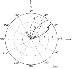
Fig. 4 Comparison of measured radiation patterns of active leaky-wave antenna array in azimuth plane (E-plane)
Continuous beam scanning was possible from -22 to +26" measured
at
-
YGHzConclusion; This Letter has presented a novel 2D beam-scanning technique using an active linear microstrip leaky-wave antenna array. We demonstrated that the main beam of a two-element active antenna array can be continuously scanned in both the azi- muth and elevation directions by tuning the varactor's DC bias. The initial results show the good potential of this circuit for use with compact and low cost transmitters, active arrays, spatial power combiners and radar applications.
ELECTRONICS LETTERS 25th June 1998 Vol. 34
Acknowledgments: This work was supported by the National Sci- ence Council under grant NSCX6-2215-E009-03 1.
0 IEE 1998
Electronics Letters Online No: 19980953
Cheng-Chi Hu and C.F. Jou (Instilute of Communication Engineering, National Chiao Tung University, Hsinchu, Taiwan, Republic of China)
Jin-Jei Wu (Department of Electric Engineering, Kao Yuan College of
Technology & Commerce, Luchu, Taiwan, Republic of China) 29 April 1998
References
1 OLINER, A.A.: 'A new class of scannable millimeter wave antennas'. Proc. 20th European Microwave Conf., September 1990, Budapest, Hungary, pp. 95-104
LIAO, P., and YORK, R.A.: 'A new phase-shifterless beam-scanning technique using arrays of couple oscillators', ZEEE Trans. Microw. Theory Tech., 1993, MTT-41, pp. 1810-1815
3 CHOU, G.J., and TZUANG, c.-K.: 'Oscillator-type active-integrated antenna: The leaky-mode approach', ZEEE Trans. Microw. Theory 4 HU, , w u , , and JOU, c.F.: 'An active frequency-tuned beam scanning leaky-wave antenna', Microw. Opt. Technol. Lett., 1998, 17, pp. 4345
MENZEL, w.: 'A new traveling wave antenna in microstrip'. Proc. 8th European Microwave Conf., 1978, pp. 302-306
2
Tech., 1996, MTT-44, pp. 2265-2272
5
Two-dimensional cylindrical dielectric
resonator antenna array
K.W.
Leung,H.Y.
Lo,K.M.
Lukand E.K.N.
YungA square 2 X 2 subarray and infinite phased array of aperture- coupled cylindrical dielectric, resonator antennas is investigated experimentally. The return loss, radiation pattem, and antenna gain are studied and compared with those of the single element antenna, and the waveguide simulator is used to measure the return loss of the element in an infinite array environment
Introduction: Since the work reported by Long et al. [l], the dielec- tric resonator antenna @RA) has attracted a number of research- ers [2 ~ 71, owing to its inherent merits of small size, light weight,
low cost, and high eficiency. The single-element DRA has been well studied, but its antenna gain is limited to
-
5dBi. In some applications a higher antenna gain is required. Recently, more effort has been devoted to DRA array design [4 - 71 to increasethe antenna gain. In this Letter, we extend the previous work of a 1 x 2 linear cylindrical DRA array [5] to its two-dimensional ver- sion, which has not been reported in the literature. The aperture- coupled source is used to excite the DRA elements, which are operated at the broadside TM,,, mode [l]. First a 2 x 2 square subarray is studied in which all elements are fed in phase. The measured return loss, radiation pattern, and antenna gain are pre- sented, and the results are compared with those of the single ele- ment. Next, a preliminary study of an infinite DRA phased array
feedline ground
{
cylindrical DRA& !:d4
dielectric substrate erS microstrip feedline aFig. 1 Geometry of configurations a Single element b 2 x 2 subarray D=;L,/2 -I b