A MODIFIED BOW-TIE SLOT ANTENNA FED BY A COPLANAR
WAVEGUIDEShih-Yuan Chen and Powen Hsu Department of Electrical Engineering and Graduate Institute of Communication Engineering
National Taiwan University Taipei 10617, Taiwan
Tel: +886-2-23635251 ext. 544, Fax: +886-2-2365 1744 E-mail: phsu@,cc.ee.ntu.edu.tw
A modified CPW-fed bow-tie slot antenna is proposed to have a wider impedance bandwidth than that of the conventional CPW-fed bow-tie slot antenna. The antenna stmcture remains simple and the better impedance matching is obtained through the insertion of a 180-degree delay slotline between the feeding CPW and one of the two parts of the bow-tie slot. A
47.4% impedance bandwidth, 2.3 to 5.1 dBi in-band antenna gains, and broadside bi-directional radiation pattems are measured and presented for an H-band prototype antenna.
1. Introduction
The bow-tie slot antenna is a broadband design conventionally used in many communication applications [ 11-[5]. However, the operating bandwidth is never wide enough for the increasing capacity and data rate demands of modem communication systems. In order to have an even broader bandwidth while maintaining a simple structure, a novel bandwidth-enhanced bow-tie slot antenna fed by a coplanar waveguide (CPW) is proposed in this paper. An H-band prototype is verified experimentally to have a wider bandwidth than that of the conventional design. 2. Antenna Structure
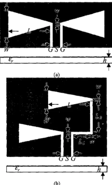
The configurations of the conventional CPW-fed bow-tie slot antenna and the present proposed bandwidth-enhanced design are shown in Figs. l(a) and (b), respectively. Both antennas have simple structures with only one layer of dielectric substrate and metalization. The geometry of the conventional CPW-fed bow-tie slot antenna is symmetrical to the direction of the feedline, while the proposed bandwidth-enhanced design is not. The conventional design is broadband and its radiation patterns near resonance resemble those of a slot dipole antenna. The outer width of the bow-tie slot
W
can be tuned for the input matching at the operating frequency, and the total length of the bow-tie slot 2L determines the resonant frequencyfo with 2L=&. In our proposed design as shown in Fig. I(b), a 180-degree delay slotline is inserted between the CPW feedline and the right hand side (RHS) part of the bow-tie slot. This will make the equivalent magnetic currents flowing on the two sides of the bow-tie slot out of phase, and thus, results in a cancellation in the broadside radiation. In0-7803-8302-8/04/$20.00
02004
IEEE 799order to avoid this, we flip the delayed
RHS
part of the bow-tie slotover
to the other side of the connecting slotline. This provides an additional 180-degree spatial phase difference to maintain in-phase magnetic current distributions on thetwo
sidesof
the bow-tieslot. The
180-degreedelay line
possessingtwo
orthogonal slotline sections, L I and L2, ensures a compact antenna size and further increases the impedance bandwidth.
3. Simulation and Measurement Results
During the design process, the length of one half of the bow-tie slot L is first determined to be &,/2 at the required center fiequencyfo just as in the case of the conventional bow-tie slot antenna. Note that the outer width of the bow-tie slot W of the proposed design is smaller than that of the conventional one. The total length of the delay slotline, L,+LZ, should be slightly less than b/ 2, and L2 is recommended to be
longer than two times of L,. Throughout the design process, simulations are carried out on a package software Ensemble [6] from Ansoff.
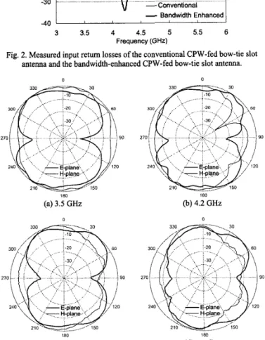
A test piece is fabricated on an FR-4 substrate with dielectric constant &r = 4.3 and thickness of 1.6 mm, and is designed to operate at 4.5 GHz. The design parameters are as follows: L=25 mm, W=12 mm, ~ 0 . 3 mm, L,=6 mm, and L2=14.7 mm. The widths of the strip and slot of the 50-R CPW feedline, S and G, are chosen to be 3 mm and 0.3 mm, respectively. Moreover, a conventional CPW-fed bow-tie slot antenna with optimized bandwidth is also implemented on the same substrate and tested for comparison. Measured retum losses of both cases are shown in Fig. 2. The measured impedance bandwidths (Return loss > 10 dB) of the optimized conventional design and the present design are 38.6% and 47.4%, respectively. An improvement of about 23% for the impedance bandwidth is achieved with our design. The radiation pattems of the bandwidth-enhanced design measured at 3.5,4.2, 5.3 and 5.7 GHz are shown in Figs. 3(a), (b), (c), and (d), respectively. The radiation pattems of the present design remain satisfactory throughout the entire frequency band, and the antenna gains measured at these four frequencies are 3.5,3.4,5.1 and 2.3 dBi, respectively.
4. Conclusion
The design of a bandwidth-enhanced bow-tie slot antenna fed by a CPW has been presented. This design demonstrates a much wider impedance bandwidth than that of the conventional CPW-fed bow-tie slot antenna. The in-band radiation pattems remain broadside and bi-directional. In addition, this antenna preserves several advantages as in the case of the conventional one, such as ease of fabrication and design, and compact in size, and it can find many applications in the integration of mobile communications.
Acknowledgements
This work is supported in part by the National Science Council, Republic of China, under contract no. NSC 92-2219-E-002-002, and in part by the Ministry of Education, ROC, under contract no. 89-E-FA06-2-4.
References
[l] E. Soliman, S. Brebels, P. Delmotte, G. Vandenbosch, and E. Beyne, “Bow-tie slot antenna fed by CPW,” Electronics Lett., vol. 35, no. 7, pp. 5 14-5 15, Apr. 1999. [2] D. Mirshekar-Syahkal and D. Wake, “Bow-tie antennas on high dielectric
substrates for MMIC and OEIC applications at millimetre-wave frequencies,” Electronics Lett., vol. 31, no. 24, pp. 2060-2061, Nov. 1995.
[3] Y. Lin and S. Tsai, “Coplanar waveguide-fed uniplanar bow-tie antenna,” IEEE
Truns. Antenna Propugat., vol. 45, no. 2, pp. 305-306, Feb. 1997.
[4] Y. Lin and S. Tsai, “Analysis and design of broadside-coupled striplines-fed bow- tie antennas,” IEEE Trans. Antenna Propagat., vol. 46, no. 3, pp. 459-460, Mar. 1998.
[5] S. Uysal, M. Leong, and C. Ng, “Bowtie patch antennas and simple arrays for wireless indoor communications,” IEEE Truns. Microwave Theory Tech., vol. 47, no. 6, pp. 738-745, June 1999.
[6] Trade mark of Ansoft Corp.
Fig. 1. Geometries of (a) conventional CPW-fed bow-tie slot antenna and (b) bandwidth-enhanced CPW-fed bow-tie slot antenna.
0 1
1
-1 0 B 3 - -20-
-
Gi
-30 -40 -Conventional-
Bandwidth Enhanced 3 3 5 4 4.5 5 5.5 6 Frequency (GHz)t
V
-conventionalI
-
Bandwidth Enhanced 3 3.5 4 4.5 5 5.5 6 Frequency (GHz)Fig. 2. Measured input retum losses of the conventional CPW-fed bow-tie slot antenna and the bandwidth-enhanced CPW-fed bow-tie slot antenna.
0 90 180 (a) 3.5 GHz 0 0 180 (b) 4.2 GHz 0 180 (c) 5.3 GHz 180 (d) 5.7 GHz
Fig. 3. Radiation pattems measured at 3.5,4.2,5.3 and 5.7 GHz of the H-band prototype.