neously. Besides, images and videos in most World Wide Web databases are in compressed formats. Therefore, it becomes an important issue to retrieve a suitable color palette from compressed domain in order to have fast and faithful color reproduction for these devices. In this paper, the color-palette design methods for compressed images and videos are presented. The proposed approaches use the reduced, rather than the whole, image for the color palette design to avoid the heavy computation in image or video decompression. Also, for compressed videos, a shifting-window scheme is proposed to smooth out color variations in the change of color palette. In these methods, we extend the dependent scalar quantization algorithm of a single image to accomplish the color palette design. Experimental results show that output image quality of proposed methods is acceptable to human eyes. In addition, empirical results show that the proposed shifting-window scheme can reduce the main problem of displaying quantized image sequences, screen flicker.
Index Terms—Color display, color palette, color quantization, compressed image, compressed video.
I. INTRODUCTION
W
ITH THE prevalence of multimedia and the Internet, more and more digital images and videos are available for people to access. The digital image or video format is usu-ally quantized with integer from 0 to 255 for each of three color components (e.g., red, green, blue). All possible combinations of three of these values gives (or 16 million) distinct colors for full-color digital display. However, due to the costs of high speed video RAM, many current PCs and workstations gener-ally have a single 8-bit frame buffer to allow only a limited number of colors, called a color palette, to be simultaneously displayed. If an acceptable output image quality is desired, it is necessary to develop a useful procedure, called color quantiza-tion, for designing the color palette.Let the set of all points of input color image be . The color
value of is represented as , where is the
associated color component value. Color-palette design, or the color quantization algorithm, is to partition the input colors into disjoint sets, , . is the predetermined size of the color palette which is usually limited by the hardware
Manuscript received December 15, 1998; revised December 28, 1999. This work was supported by National Science Council, R.O.C., under Contract NSC 88-2213-E-002-047. This paper was recommended by Associate Editor R. Lancini.
S. C. Pei and L. F. Ho are with Electrical Engineering Department, National Taiwan University, Taipei, Taiwan, R.O.C. (e-mail: [email protected]).
C. M. Cheng is with Telecommunication Lab, Chunghwa Telecommunication Co., Taiwan, R.O.C. (e-mail: [email protected]).
Publisher Item Identifier S 1051-8215(00)07557-1.
process of color quantization can be represented by
(1) where indicates the output of the color-quantization algo-rithm and is the set of available output colors in the color palette. Thus, the main issues in the color-palette design are how to find the representative color and partition the colors into color sets, .
In the past, the color-palette design focused on uncompressed data. For one single image, several color-quantization algo-rithms have been proposed. Heckbert has proposed a median cut (MC) algorithm [1], where the color space is recursively divided into rectangular regions with equal color occurrence and their centroids being representation colors. Braudaway [2] has presented an improved Popularity algorithm which reduces the frequency of neighbors of a selected color to prevent the color concentration in one neighborhood. Recently, the popular vector quantization (VQ) technique [8] is applied to the color-palette design, too. The colors in input image are used as training vectors in order to refine the initial rough palette. But VQ-type algorithms are usually computational intensive such that they are not suitable for real-time processing. Pei and Cheng have suggested a dependent scalar quantization (DSQ) algorithm [3], which exploits dependency of input colors and sequentially partitions the color space. The experimental results show that the DSQ can reduce the computation complexity and its output image quality is acceptable to human eyes. Also, some color-quantization researchers have focused on the processing of image sequences. Roytman and Gotsman [12] have proposed an algorithm for dynamic color quantization of image sequences, which quantizes each image independently to produce a different color palette for each image. Besides, they suggest the approach of color palette filling to prevent frequent switching of color palettes, which leads to the problem of screen flicker.
However, with the consideration of communication band-width and storage space, most image or video data nowadays comes in compressed format. Extra heavy computation of image or video decompression is required before any above-mentioned color quantization is employed. How to design the color palette directly from compressed data has thus become a significant issue. In this paper, we extend the DSQ to present some novel color-palette design methods for com-pressed images and videos. Concerning comcom-pressed images, the proposed method use the reduced image in compressed domain to design color palette. For compressed video, the
(a) (b) Fig. 1. (a) Procedures of color space partition by the DSQ. (b) Partition of 2-D signal space by the DSQ.
proposed method extracts key color frames from compressed video data in order to alleviate the computation burden and storage usage. Besides, to display longer sequences without screen-flicker problem, we propose a shifting-window scheme. This paper is organized as follows. In Section II, the DSQ al-gorithm is briefly introduced. In addition, we describe the pro-posed approach for compressed images, which uses the reduced image rather than the whole image for the color-palette design to avoid the heavy computation in image decompression. In Sec-tion III, the technique of extracting key color frames for com-pressed videos is presented and a shift-window scheme is pro-posed to solve the screen-flicker problem. Section IV reports the simulation results of proposed methods Finally, a conclusion is made in Section V.
II. LIMITEDCOLORDISPLAY FORCOMPRESSEDIMAGE
Concerning compressed image, JPEG [4] is the most widely accepted picture compression standard, which not only provides good quality, but also the compression ratio is high. When dis-playing any JPEG image on machines with limited color-display capability like most SUN workstations, the default color palette is usually not suitable. But the design of the color palette re-quires the original image, which is not available for JPEG im-ages without decompression. The procedures of decompression also require lots of computations and much space for storage. Therefore, it is essential to design schemes which use few parts of decompression to extract the color palette.
In this section, we will explain two methods of color-palette design for compressed image, which are the extensions of the DSQ [3]. Before the descriptions of proposed methods, the DSQ is briefly introduced.
A. Review of DSQ
The DSQ is designed to quantize color images with both good quality and fast speed. As displayed in Fig. 1(a), the DSQ par-titions color space of an image in a dependent way in order to fully utilize the correlations of color components of an image. The partition used is the binary moment preserving (MP) thresh-olding technique. The DSQ includes two stages: 1) bit alloca-tion for different color components and 2) recursive binary MP thresholding. The purpose of bit allocation is to let every bit
in the designed color palette provide as much information as possible. Usually, the wider distribution of color values in one color component, the more bits are needed to this component. To find suitable thresholds partitioning color space and representa-tive colors of an image, the DSQ employs recursive binary MP thresholding. The principle is that for one specific color com-ponent , the total pixels are divided into two classes using the binary MP principle. These two classes are then recursively di-vided into two subclasses until the number of bits allocated to this color component is reached. The binary MP thresholding is based on the idea that after thresholding, the moments up to some order are kept the same.
Now we consider the case using binary MP thresholding to partition color component into intervals. The range of the color component , with boundary values 0 and , is first partitioned into two intervals and
, where represents the threshold obtained by first bi-nary MP thresholding. Then the interval is partitioned
into two subintervals and , where
is the threshold obtained by second binary MP thresholding. Similarly, is partitioned into two subintervals and by third binary MP thresholding. If we continue the procedure recursively by using the binary MP thresholding times and order the resultant thresh-olds according to their values, the output thresholding levels
will be determined, i.e.,
for .
The steps to design a DSQ color palette are concluded as fol-lows.
1) Use the bit-allocation procedure to find out the total thresholding levels in each color component.
2) Do the recursive binary MP thresholding on and
cal-culate the threshold levels .
3) Do the following steps times.
a) Perform the recursive binary MP thresholding on in those pixels falling in the span
and calculate the associated thresholding levels .
b) Do the following step times.
Apply the recursive binary MP thresholding on in the pixels within the long bar limited
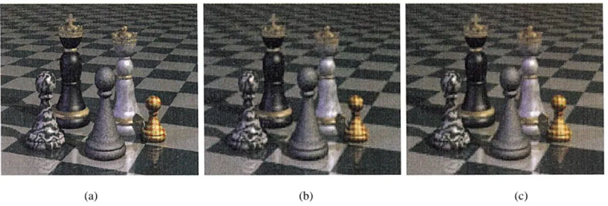
(a) (b) (c) Fig. 2. (a) Decoded JPEG image. (b) Its DC image. (c) Enlarged DC image.
and compute the associated thresholding levels .
4) Assign the centroid of color points inside the cube formed by step 2 and 3 as a representative color.
The total number of binary MP thresholding needed in the
DSQ is . A covering
of quantization in 2D signal space is illustrated in Fig. 1(b). As we can see, the DSQ will cluster color points appropriately and not waste any cell.
B. Design of Color Palette from the DC Image
The step which needs most computations in decoding a JPEG image is inverse discrete cosine transform (IDCT). If we design the color palette for a JPEG image in an uncompressed domain, we must handle this computation-intensive step, IDCT. More-over, in doing it this way, the data size of the uncompressed image is much larger than that of the original compressed image. These drawbacks become more serious when several JPEG im-ages desire limited-color displays in the multi-tasking window system like Window95 or XWindow. To overcome these trou-blesome problems, we must find a method which uses a min-imum of JPEG decompression procedures to extract the suitable color palette in the compressed domain.
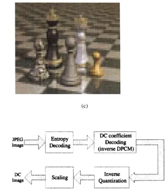
The proposed method exploits the DC image rather than full-resolution image for finding color palette. The DC image is the image consisting of DC coefficients of all blocks in the image. The most important advantage of doing this is the low computation complexity, as compared to fully decoding the image. IDCT is not longer necessary and even the zigzag scan-ning or run-length decoding can be skipped for extracting the DC image. Although the fine spatial details of the image are lost in the DC image, the most important feature required in de-signing the color palette, the color characteristics of the image, is kept. As shown in Fig. 2, it is obvious that the DC image re-serves the most significant colors in the original image, which are needed for acceptable limited-color display. The DC image can also be utilized in other compressed domain applications. Nakajima [10] has used the DC image performing scene-change detection of video data.
The procedures to extract the DC image of the JPEG image are shown in Fig. 3. The extracted DC image is then processed by the DSQ to get the color palette. The obtained color palette can be stored in the header of the JPEG image. The insertion of
Fig. 3. Extraction of the DC image from a JPEG image.
color palette in the header of JPEG image indeed increases the output bit-rate. However, this increment is not significant. For example, we consider the following case of compressed image: 1) the original color image with size being
com-pressed with ratio 12 : 1;
2) the design of color palette generating 256 representative colors and the bit allocation via the DSQ algorithm to three color components being (2, 3, 3).
Then, the header of JPEG image should allocate bytes for representative colors and
bytes for the partition boundary generated by the DSQ algorithm. This allocation will increase the bit rate as
.
On receiving the JPEG image, the receiver can decide whether it is using the color palette for better limited-color display quality or not. If the color palette extracted by the proposed scheme is selected, we utilize the boundaries of color cubes partitioned by the DSQ to obtain the displayed color of each pixel of the decoded JPEG image. The search of the associated representative color for each pixel is based on the well-organized tree structure of color space partition by the
DSQ. It takes at most comparisons.
Finally, scaling is needed because the DC coefficient
is for an block, which is eight times larger than the real DC value.
C. Extension to the AC Image
If the image size of the JPEG image is too small, the extracted DC image might not contain enough color information in the original image. Also, in some applications, the original image is too large to be analyzed efficiently. It is desirable to analyze a small-size image rather than the original image of full resolu-tion. Thus, the DC image is not suitable for the color-palette
(a) (b) (c) Fig. 4. (a) Decoded JPEG image. (b) Its enlarged 1DC+ 3AC image. (c) Its enlarged 1DC + 2AC image.
design. In these situations, we observed from several experi-ments that the AC image, which is constructed by DC and three
AC coefficients ( , , and ) of all
blocks in the JPEG image, can provide enough color informa-tion. This image is designated as the 1DC 3AC image in this paper. These coefficients are selected because they can generate the AC image easily. The inverse two-by-two DCT is given by
(2)
where with and , 1 are the values of the
pixels of each block in the 1DC 3AC image.
But one noticeable thing is that the AC coefficient is usually zero or much smaller than the other three coefficients. Therefore, in the 1DC 3AC image, the influence of the co-efficient could be ignored in most situations. In this way, we choose the 1DC 2AC image rather than 1DC 3AC image for designing the color palette. In getting the 1DC 2AC image, (2) is still applicable, with . One advantage of using 1DC 2AC image is that the needed run-length de-coding is fewer than that in 1DC 3AC image. One example of 1DC 3AC and 1DC 2DC image is shown in Fig. 4. Com-paring Fig. 2 with Fig. 4, it is very obvious that more details are kept in the 1DC 3AC and 1DC 2AC images. Further-more, the 1DC 2AC image is almost the same as the 1DC 3AC image. Hence, the 1DC 2AC image is more preferable when the image size is too small or more details in the image are needed.
Compared with the extraction of the DC image, the computa-tions of getting the 1DC 3AC image or 1DC 2AC image in (2) are very simple, too. They only involve additions and shifts, which are most desirable in either software or hardware imple-mentations. The only price paid is getting those AC coefficients. The AC coefficients could be acquired by several run-length de-coding steps which can be done by using a look-up table. The procedures of extracting the 1DC 3AC image or 1DC 2AC image are shown in Fig. 5.
Fig. 5. Extraction of the 1DC+ 3AC or 1DC + 2AC image from a JPEG image.
III. LIMITEDCOLORDISPLAY FORCOMPRESSEDVIDEO
Now more and more video clips are able to be accessed in some World Wide Web databases. However, with the limit of bandwidth of internet, those video clips are usually compressed by using MPEG [6], [7] or H.26x [5] format. In this condition, how to analyze the video clips to design a suitable color palette for those machines with limited color display becomes impor-tant. In this section, we will introduce methods of color-palette design for MPEG compressed video.
Similar to JPEG images, the low-resolution DC images of MPEG video, called DC sequences, are first extracted for color-palette design. Additionally, to avoid huge computation costs, we will only apply the DSQ to those DC images, called key color frames, which contain the major color information of the entire DC sequence, for obtaining the color palette of MPEG video. From the observation of DC sequences, we noticed that color information inside a frame is unchanged for most of the se-quence except key color frames, which consists of color changes in the sequence. Thus, detection of color changes is essential for finding key color frames. The detection of key color frames is based on two steps and introduced in the following subsection:
1) detection of potential key color frames;
2) detection of key color frames and extraction of color palette.
Besides, if only one fixed color palette is used, the degra-dation would get worse and worse as the sequence length gets longer. To overcome this problem, a multiple color-palette scheme called shifting-window scheme is proposed to display compressed video with good quality even when the sequence length is getting longer.
[11] and is shown in Fig. 6.
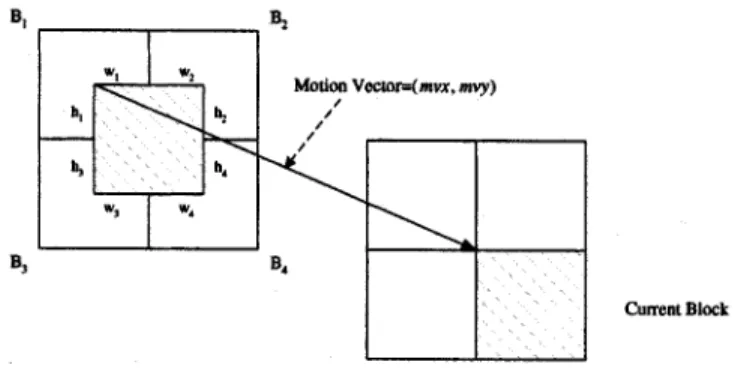
Here, is the block with motion vector
pointing to the current block of interest and and are the four neighboring blocks which derive the refer-ence block . We can express the DC component of DCT coefficients of , denoted as DCT , in the following equation:
DCT DCT (3)
where are weighting factors related to the motion vector. This precise calculation of DCT coefficients is time-con-suming. Since we are only interested in the DC component, the first-order approximation is used rather than precise calculation
DCT DCT (4)
where and are the overlapping width and height of in block . It can be shown that corresponds to in (3), and this is why it is called a first-order approximation. Although the approximation error will accumulate, the error is acceptable in most cases because the GOP size is usually small and the error will reset to zero at every I frame. The other advantage of this approximation is that it requires only the motion-vector information and the DC values in the refer-ence frames. This approximation approach can also be applied to a B frame where two reference frames might be needed. The problem of half-pixel-wise prediction can be solved by using the average of larger blocks depending on the motion vector. The block is needed if half-pixel-wise prediction occurs in both and direction. The block is used for half-pixel accuracy only in the direction and the block is for di-rection only.
B. Key Color-Frame Detection for Compressed Video
After the DC sequence is derived from an MPEG video, we use its DC images for key color-frame detection. To represent color information of a frame, the hue component of HSV space [13] is adopted in this paper. The hue component has been widely accepted as a good candidate of representing color difference. Using this representation, we compare the normalized difference of hue histogram between consecutive frames in order to detect boundaries between consecutive color changes. The principle behind this is that two frames having a unchanging background and objects will show little difference in their corresponding hue histograms. The normalization procedure is utilized for reducing the impact of noise imposing
Fig. 6. Current block, motion vector, and reference block.
on the hue histograms of consecutive frames. The normalized hue difference between the hue histograms of the th and ( )th frame, , is given by the following equations:
NHD (5) where NHD for otherwise (6) with and being hue histograms of the two con-secutive frames, respectively, and of (5) being the number of hue component bins in comparison. In (6), we choose the min-imum value of and to normalize the hue differ-ence. The condition is set to reflect the situation when pixels with the certain hue value exists in frame , but not in frame .
Similar to luminance change of the DC sequence, we have ob-served that color change is also a local activity which involves details regarding several neighboring frames. For scene-change analysis, Yeo and Liu [9] have suggested setting the threshold of luminance change in order to match the local activity. We adopt this approach to detect color changes in this paper and choose a sliding-window thresholding technique proposed by Yeo and Liu [9] to avoid false alarms which might occur in camera oper-ations or object changes. In this technique, frames with hue differences are examined in a local range. Inside this local window, a color change from ( )th to th image occurs if the following conditions are satisfied.
1) The difference is the maximum with the window, i.e., . 2) is also times of the second maximum in this window. After examination of each window, the window is shifted one frame to prepare the next examination until the whole sequence is processed. In criterion 1, the parameter is set to be smaller than the minimum duration between two color changes, but large enough to avoid false alarms. This is because as the window size gets smaller, the threshold is closer to be a global approach which is unfavorable for color-change detection. If we set for
Fig. 7. Detection of key color frame in compressed domain.
a 30 frames/s video sequence, it means that there cannot be two color changes within a second. The parameter in criterion 2 is imposed to guard against some camera operations such as fast panning or zooming. For these operations, the hue differences would maintain consecutive peaks across several frames. From experimental results, we understand that the design of depends on the tradeoff between increasing the detection rate and decreasing the false alarm rate. It has been found that the values of
varies from 2.0 to 4.0 give good results.
Through the above sliding-window thresholding scheme, the detected frames are called potential key color frames. From experimental results, we observed that there are redundant false-alarmed frames, which do not contain significant color information, inside these potential key color frames. Then, we adopt a coarse-to-fine strategy to eliminate those false-alarmed frames. In this strategy, these potential key color frames is processed one more time by the sliding-window thresholding scheme. After this examination, the detected frames are desired key color frames which are then used by the DSQ for the extraction of color palettes. We illustrate the proposed scheme of detecting key color frames for compressed video in Fig. 7.
To do limited-color display with the color palette extracted by the proposed scheme, we employ the same procedures as for the compressed image. Using the well-organized boundaries of color cubes partitioned by the DSQ, pixels of each image of decoded MPEG sequence are mapped to their associated repre-sentative colors.
C. Shifting-Window Scheme
If only one fixed color palette is assigned to the whole sequence, the performance of color quantization is getting worse as the sequence length gets longer. On the other hand, if a color palette is designed for every key color frame, a serious visual artifact, screen flicker, may occur when the color palette is changed for these key color frames [12]. This problem happens because there is a sudden change of images colors. When the frame buffer of the display contains an image, a new color palette which belongs to the next image is already active. This phenomenon of screen flicker is sharp and unpleasant to human eyes.
TABLE I
APSNROFDECODEDJPEG IMAGE, DECODEDIMAGEQUANTIZED BYPROPOSEDMETHODUSING THEDC IMAGE ANDDECODED
IMAGEQUANTIZED BY THEISQ
TABLE II
APSNROFDECODEDJPEG IMAGE, DECODEDIMAGEQUANTIZED BYPROPOSEDMETHODSUSING THEDC IMAGE,THE1DC+
3AC IMAGE AND THE1DC+ 2AC IMAGE
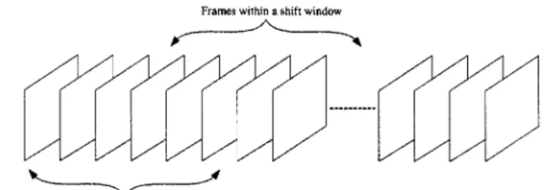
To solve the screen-flicker problem, we still use the DSQ to design color palettes for the sequence, but a color palette is de-signed for each fixed-length shifting-window in the sequence. The procedures of color-palette design in the video sequence of each window are the same as mentioned above. The key color frames in each shifting window are detected and applied to the DSQ for the color-palette design as depicted in Fig. 8. These windows contains overlapping frames, which cause the color distribution to not vary too much from window to window even if the color change occurs. As a result, the DSQ can generate smoothly varying color palettes for the sequence if the bit-allo-cation procedure is fixed. In addition, since every entry of the color palette of the processed window would not differ signif-icantly from that of the next window, screen flicker is greatly reduced.
IV. EXPERIMENTALRESULTS
To illustrate the performance of proposed color-quantization methods for compressed image, four different RGB color ages (“Boats,” “Jet,” “Lena,” and “Toys”) are tested. These im-ages are first compressed by JPEG baseline compression. Then the color palette of 256 colors is designed by the DSQ from the
(c) (d)
Fig. 9. “Lena” image. (a) Original image. (b) Decided JPEG image. (c) Decoded image quantized by proposed method using the DC image. (d) Decided image quantized by the ISQ.
(a) (b)
(c) (d)
Fig. 10. “Chess” image (320 2 240). (a) Original image. Decoded images quantized by proposed methods using (b) the DC image, (c) the 1AC + 3AC image, and (d) the 1DC+ 2AC image.
extracted the DC image, DC 2AC image, or DC 3AC image. To evaluate the performance, the average peak signal-to-noise-ratio (APSNR) is used. The APSNR criterion is given by
APSNR
TSE (7)
where TSE is the total square error of three color components between the original and quantized images. The results of pro-posed method using the DC image are shown in Table I. For comparison, the APSNRs of the decoded JPEG image and its color-quantized image by the independent scalar quantization (ISQ) [14], which subdivides each color component
individu-Fig. 12. Sum of hue difference plot of “News”:S versus l.
ally with a fixed number of levels, are also included in Table I. The resultant images for “Lena” are displayed in Fig. 9. It is no-ticed that the performance of the proposed method is above 30 dB on average and better than that of using the ISQ. Although some other better color-quantization methods except the ISQ can be applied to the decoded JPEG image, they usually need extra heavy computation to obtain the color palette. This would slow the speed of limited-color displaying process. For instance, if the DSQ is applied to the decoded JPEG image “Lena” with size , the APSNR value of color-quantized image is 32 dB. However, the computation time to obtain the color palette is 12 s when using a SUN SPARC20 workstation. This com-putation time is larger than those of proposed schemes, which are 1.3, 2.3, and 2.4 s for using the DC image, the DC 2AC image, and the DC 3AC image, respectively, when the same image and workstation are tested. On the other hand, since the proposed schemes has extracted the color palette from the com-pressed domain in advance, the displaying process of the de-coded image is fast.
Then we chose four other small-sized images to demonstrate the performance of other proposed methods. The empirical re-sults are shown in Table II. Normally, the performance of using the 1DC 2AC image is better than that of using the DC image. For the “Lena” image, because the DC image is only , which is exactly the size of the color palette, so the per-formance gain with the 1DC 2AC image is very obvious. But as the image size gets larger, the gain becomes less clear. The small difference between the 1DC 3AC and the 1DC 2AC images for color-palette design can be seen in these results.
Fur-observations.
To evaluate the performance of the proposed method for com-pressed videos, a test sequence “News,” which has 300 YUV frames with size , is used. The sequence consists of three main video segments which are news conference of a president candidate, a TV news reporter and news of a trop-ical storm. There are special effects of dissolving, fading in and fading out existed within each transition of two segments. This test sequence is first compressed by MPEG-1 compression. Then the proposed scheme is applied to design a color palette of 256 colors on the YUV color space. The color components were quantized in the order of Y(Luminance) first, then U and V last. The number of bits in each color component after bit allocation in the DSQ are 4(Y), 2(U), and 2(V).
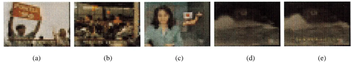
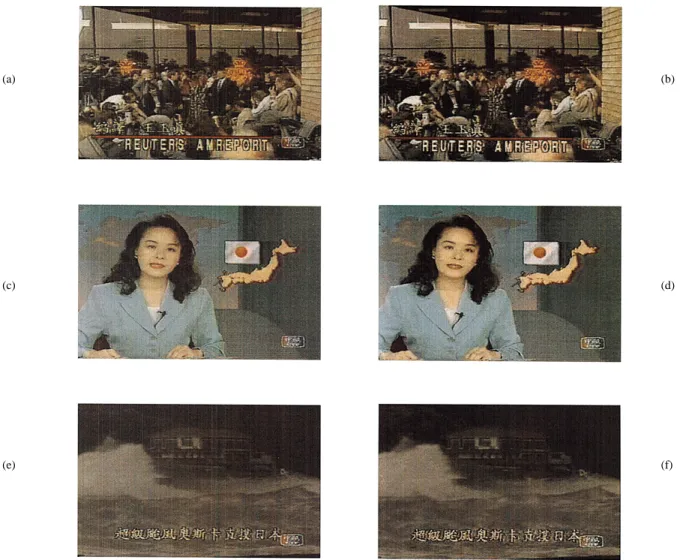
The detected key color frames from the extracted DC sequence are frame 0, 3, 90, 195, and 210 which are shown in Fig. 11. The parameters of criterion 1 and 2 used to find a color change are set to be 7 and 2, respectively. The sum of hue difference in the first step of scheme of detecting key color frames is plotted in Fig. 12. As we can see, these frames indeed represent significant color difference. Frame 210 is detected because the yellow caption appears. Fig. 13 shows the selected original frames 30, 120, and 220 and their decoded MPEG-1 frames quantized by the proposed scheme with the color palette designed from above key color frames. We plot in Fig. 14 the PSNR distribution of luminance component of the decoded MPEG-1 sequence and the decoded sequence quantized by the proposed scheme. In this figure, the average PSNR of the decoded MPEG-1 sequence is 33.9805 dB and that of the proposed scheme is 32.4647 dB, which shows only about 1.5 dB lost on average in the color quantization. When we analyze Fig. 14, it is noticed that some peaks or intra-frames among frame 90 and frame 210 have about 5 dB lost between PSNR values of the decoded MPEG-1 sequence and the proposed scheme. Normally, decoded intra-frames of the MPEG-1 sequence are good quality, since no motion estimation is involved. For these intra-frames, it shows that the matching of colors of the decoded MPEG-1 frame with those of the original frame is better than that of the representative colors obtained from the proposed scheme. However, since the PSNR values of the proposed scheme for these frames are around 35 dB, we do not perceive significant degradation of picture quality in experiments. The color palette obtained by the proposed scheme is shown in Fig. 15(a). Concerning the computation time, the proposed method took about 8.8 s to extract a color palette for the test sequence when using a SUN SPARC20 workstation.
(c) (d)
(e) (f)
Fig. 13. Original and quantized frames of “News.” (a), (c), and (e) are original frame 30, 120, and 220, respectively, and (b), (d), and (f) correspond to quantized frame 30, 120, and 220, respectively.
Fig. 14. PSNR in the sequence “News.” The solid curve is for the decoded MPEG-1 sequence and the dotted curve corresponds to the proposed scheme.
We also executed the shifting-window scheme with the size of shifting-window being 150 and the size of overlapping frames between neighboring windows being 75 on the test se-quence. This configuration results in three shifting windows to cover the test sequence. The designed color palettes for frames
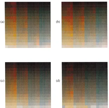
0–149, 75–225, and 150–299 are shown in Fig. 15(b)–(d). As we can see, the color palette of frames 150–299 contains more dark colors, which appear in the video clip of the tropical storm. The gradual changes can be observed among these color palettes. When the corresponding quantized sequence is played back with frames 0–74 using palette of Fig. 15(b), frames 75–224 using palette of Fig. 15(c), and frames 225–299 using palette of Fig. 15(d), we have seen that screen-flicker phenomenon is insipid and acceptable to human eyes.
V. CONCLUSION
In this paper, we have proposed color-quantization methods for compressed image and video, which are based on block-wise 2D-DCT operations. The proposed methods adopt the DSQ, which compromises complexity and quality, to design the color palette. For the compressed image (mainly JPEG image), the proposed method can use the DC or 1DC 2AC image to design the color palette. The main advantage of this method is the low computational load as compared to the traditional methods which need to decode the whole image. As for the com-pressed video (basically MPEG video), the same technique for the compressed image is adopted. We design the color palette
(c) (d)
Fig. 15. (a) Color palette for the sequence “News” when only one color palette is used. (b)–(d) Color palettes for the same sequence for the shifting-windows scheme.
from key color frames of the DC sequence rather than the whole sequence in order to reduce the computation complexity. The decoded images quantized by the proposed methods for com-pressed image and video are acceptable to human eyes. Finally, a shifting-window scheme to solve screen-flicker problem is pro-posed. As shown by experimental results, we understand that this scheme can reduce the screen-flicker problem.
ACKNOWLEDGMENT
The authors would like to thank anonymous reviewers who made many useful comments. Their help is gratefully appreci-ated.
REFERENCES
[1] P. Heckbert, “Color image quantization for frame buffer display,” Comput. Graph., vol. 16, no. 3, pp. 297–397, July 1982.
[2] G. Braudaway, “A procedure for optimum choice of a small number of colors from a large color palette for color imaging,” in Proc. Electronic Imaging ’87, San Francisco, CA, 1987.
[3] S. C. Pei and C. M. Cheng, “Dependent scalar quantization of color images,” IEEE Trans. Circuits Syst. Video Technol., vol. 5, pp. 124–139, Apr. 1995.
[4] G. K. Wallace, “The JPEG still picture compression standard,” Comm. ACM, vol. 34, no. 4, pp. 30–44, Apr. 1991.
[5] “Video Codec for Audiovisual Services at Px64 kbits,”, Draft Revision of the CCITT recommendation H.261, WP XV/1 Rep. Part II, Dec. 1989. [6] “MPEG Video Committee Draft,”, ISO-IEC/JTC1/SC29/WE11/MPEG
90/176, Dec. 1990.
[7] D. Le Gall, “MPEG: A video compression standard for multimedia ap-plication,” Comm. ACM, vol. 34, no. 4, pp. 46–58, Apr. 1991.
[13] W. K. Pratt, Dig. Image Processing. New York: Wiley, 1991. [14] J. D. Foley, A. V. Dam, S. K. Feiner, and J. F. Hughes, Comput.
Graphics: Principles and Practice. Reading, MA: Addison-Wesley, 1990.
Soo-Chang Pei (S’71–M’86–SM’89–F’00) was
born in Soo-Auo, Taiwan, in 1949. He received the B.S.E.E. degree from the National Taiwan Univer-sity, Taipei, Taiwan, in 1970, and the M.S.E.E. and Ph.D. degrees from the University of California at Santa Barbara in 1972 and 1975, respectively.
He was an Engineering Officer in the Chinese Navy Shipyard from 1970 to 1971. From 1971 to 1975, he was a Research Assistant at the University of California at Santa Barbara. He was Professor and Chairman in the Electrical Engineering Department for both Tatung Institute of Technology and National Taiwan University during 1981–1983 and 1995–1998, respectively. Presently, he is the Professor of the Electrical Engineering Department, National Taiwan University. His research interests include digital signal processing, image processing, optical information processing, and laser holography.
Dr. Pei is a member of Eta Kappa Nu and the Optical Society of America.
Ching-Min Cheng was born in Taipei, Taiwan,
in 1959. He received the B.S.E.E. degree from the National College of Marine Science and Technology, Keelung, Taiwan, in 1982, and the M.S.E.E. degree from the University of California at San Diego in 1986. In 1996, he received the Ph.D. degree in electrical engineering from the National Taiwan University, Taipei, Taiwan.
From 1983 to 1984, he was an Engineering Officer in the Chinese Airforce Anti-Aircraft Corps. From 1986 to Aug. 1989, he served as a Patent Examiner in the National Bureau of Standards. Since September 1989, he has been with Telecommunication Labs, Ministry of Communications, Taiwan, as a Research Engineer. His research interests includes digital signal processing, video com-pression, and multimedia communication.
Lung-Feng Ho was born in Keelung, Taiwan, in
1974. He received the B.S. and M.S. degrees in elec-trical engineering from National Taiwan University, Taipei, Taiwan, in 1996 and 1998, respectively.
He is currently serving in the Army. His research interests include image and video processing.