716 OPTICS LETTERS / Vol. 13, No. 9 / September 1988
Electro-optical effect of a magnetically biased ferronematic
liquid crystal
Shu-Hsia Chen
Institute of Electro-Optical Engineering and Department of Electrophysics, National Chiao Tung University, Hsinchu,
Taiwan 30050, China
B. J. Liang
Institute of Electro-Optical Engineering, National Chiao Tung University, Hsinchu, Taiwan 30050, China
Received January 29, 1988; accepted June 8, 1988
The electro-optical effect of a magnetically biased ferronematic liquid-crystal film is investigated by using birefrin-gence measurements. When a magnetic field is applied, the threshold voltage of the Freedericksz transition no longer exists. The dependence of the birefringence on the magnetic field strength in the low field regime is presented. A theory that accounts for the results is given.
The electro-optical effect in liquid crystals (LC's) has played an important role in technological applica-tions. It was observed by Freedericksz that, if a ne-matic liquid-crystal (NLC) cell is aligned so that the smallest dielectric constant is parallel to the applied field, there exists a threshold field below which the molecular orientation is unaffected.1 Above the threshold the orientation of the director gradually dis-torts toward the minimum energy configuration and induces the birefringence. Meyerhofer2reported that a Freedericksz transition (FT) threshold for a
pretilt-ed NLC cell no longer exists.
Usually a NLC cell with a pretilt angle can be achieved by surface treatment.3 In our work we used a ferronematic4 LC, which has the unique property of having a high magneto-optical effect. Consequently, a pretilt angle is easily obtained and tuned by an exter-nal magnetic field. No threshold voltage of the FT has been observed. This can be verified theoretically. The birefringence measurements and theoretical re-sults are in good agreement in the low field regime.
We consider a homeotropically aligned ferrone-matic LC film of thickness D. The geometry is
depict-ed in Fig. 1. The local magnetization M is
perpendic-ular to the local nematic director n. Both electric field
E and magnetic field H are applied along the z axis,
which is the direction of the unperturbed director no. Neglecting the effect of the disclination5 defects near the magnetic grains, the system free energy per unit
area of the wall is given by
=D/2
r1
2 0)_dof
dZ -K
33(1l+
K sin2()
J-D/2
L
2-
MH
sin
0(z)- (Ecos
(1)where K = (K11 - K33)/K3 3, K1l and K33 are the splay
and bend elastic constants, respectively, and AC = ell
-EI is the dielectric anisotropy due to the quasi-static electric field.
Considering a small deviation from the original ar-rangement, that is, 0(Z) << 1, and using the approxima-tion Kll _ K3 3, the free energy becomes
f
J
dZ[
K33(
)
- MH0(Z) - 1eE2(1 - 02)] (2)
8xr
Let 0O(Z) represent the pretilt angle induced by the magnetic field H. Matching the boundary conditions
0(±D/2) = Oo(+D/2) = 0, we expand O(z) and OO(z) in
Fourier series: 7Z v(Z) = / , cos(2n
+ 1) 7D
n=OiZ
oo(Z) =I1
Vn cos(2n + 1) 7 D n=OIn terms of u's and v's the difference of free energy is
Af A(0) - o) (Un n)
D
n0o -IMH(-l)n 2D (un0 -vn)E
( ) (2n
+ l)r(n
n
AeE2 D 2 eE2D+ 8-r2Eu2
(3)
naoInstability occurs whenever Af becomes negative.
September 1988 / Vol. 13, No. 9 / OPTICS LETTERS 717 Ip I I I- Z=+ Q =0
HIE.Z. beam, / -> / Z=0 G e
M 0fn Hie ii,,
LX '.- l llz=O
perimental setup. B.S., beam splitter; M., mirror; P.,
polar-izer; E.F., Earth field; L.C., liquid-crystal cell; R.P., rotating
polarizer; C.P., chopper; A and B, photodiodes; Amp., lock-in amplifier; P.C., Apple II computer; F.G., function
genera-tor.
This can be achieved by any E2> 0. Putting U2m-1 =
V2m-1 for any integer m, the criterion for instability
becomes
E
2>{K3D
(i2m + V2D
4(AD
2m)[(4m+
1)2r] (4m + 1)7r 87r X (U2m - V2m). ACe D 2 -1 8- 2 -2mA normally incident laser beam with wavelength X should have its extraordinary component experience an induced phase change
6 =
Kr
2(ne
- n))D5M2H21- ACE2 D2 260K 3 3 2
327rK3 3
J
(7)where no and ne are, respectively, the ordinary and the maximum extraordinary refractive indices of the sam-ple.
In our experiment, the ferronematic LC is magneti-cally doped
N-p-methoxybenzylidene-p-butylani-line,4 with a volume filling factor f = 1.89 X 10⁻⁶. The magnetic particles are -y-Fe2O3 needles 0.5 ptm long
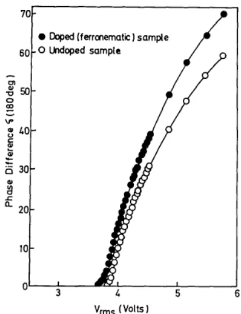
70-* Doped (ferronematic) sample
60 O Undoped sample
50
,0 -'p 3
Vrms (Volts)
Fig. 2. Experimental values for the electric-field-induced
birefringence.
It is obvious that for any E2> 0 there exist U2m 0 V2m
such that instability can occur. In other words, there is no threshold for the FT.
The reorientation angle of the director, 0(Z), can be calculated by using a free-energy minimization
proce-dure4'6that yields p0(z)
ZC1/2 = o (1 + K sin 0)1/2
X [1 _2(A sin0+Bsin2 0) -1/2do (5)
where A = -MH/K 3 3, B = -AeE2/87rK3 3, C = 2(A sin Om + B sin2 Om), and 0
m is the maximum molecular
reorientation angle in the LC sample. For a small
molecular orientation distortion (0m << 1), it is easy to get 0(Z) = 00(Z)(I -Om =mHD 2 1 0m 8K3 3 1 AEE2D2 327rK3 3 ACEE2D2 _ 7rK3, 32w7K3 3 (6)
where 0O(Z) = MH/8K3 3 (D2- 4Z2) is the pretilt angle.
~0
-D 1 an a-2 Vrms (Volts)Fig. 3. Phase different versus voltage for samples with vari-ous magnetic-field-induced pretilt angles.
11
718 OPTICS LETTERS / Vol. 13, No. 9 / September 1988 '& 4 -V
~.A
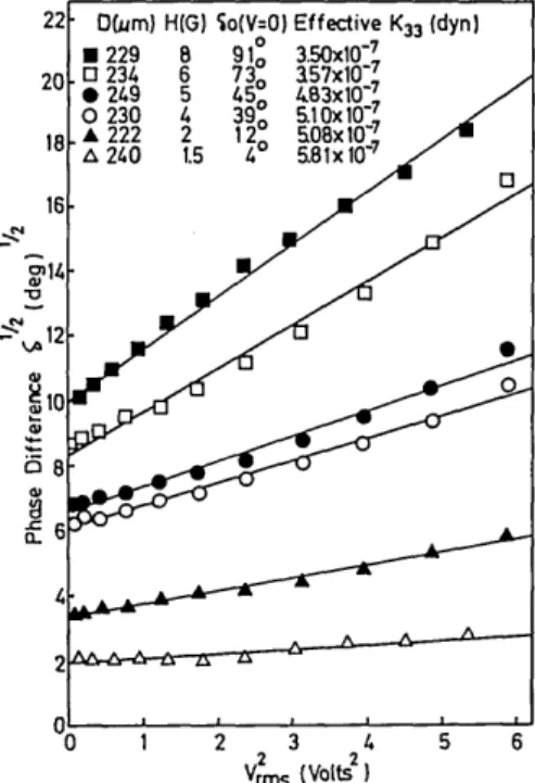
l 3 4 2 2 Vrips (volts )Fig. 4. Phase-difference dependence on voltage, a KV2, as
predicted by Eq. (7).
and have an aspect ratio of -7:1. Their magnetic dipole moment points along the long axis of the parti-cle and is 70 emu/g. To prevent clumping, these nee-dles are coated with dimethyl octadecyl aminopropyl trimethoxysilyl chloride (DMOAP). The sample films are made by sandwiching the ferronematic liquid crystal between two glass plates. The glass windows are first coated with indium tin oxide, which serves as transparent electrodes, and then with DMOAP to achieve homeotropic alignment.7
The field-induced birefringence is measured with a He-Ne probe laser by using a modulation technique originally devised by Lim and Ho.8 During the mea-surement the sample film is placed horizontally. The magnetic dipole moment of the ferronematic matrix is first aligned by the horizontal component of the Earth's field. The biasing magnetic field is applied with a pair of Helmholtz coils such that H || n. A
quasi-static electric field at 1 kHz is applied normal to the glass window. A block diagram of the experimen-tal apparatus is shown in Fig. 1. Briefly, the probe beam is split, and the main measurement beam passes
successively through a polarizer, the sample, a X/4
plate, and a rotating polarizer before being detected by photodiode A. The polarization direction of the probe beam makes an angle of 45° with the horizontal component of the Earth's field. The axis of the X/4 plate is aligned with the probe-laser polarization di-rection. A polarizer is mounted at the end of the open shaft of a synchronous motor. The shaft of the motor
also carries a chopper, which intercepts the reference beam. The phase difference between the signals from the photodiodes is measured with a phase-sensitive detector and recorded.
The measured electrocontrolled birefringence of the undoped and doped samples is given in Fig. 2. Both samples show a typical critical behavior near the
threshold voltages, which are 3.88 and 3.77 V,
respec-tively. Using Vth = 7r 4w7rK33[ACE and AC = -0.5, the
corresponding values of the elastic constant, K33, are
6.74 X 10⁻⁷ and 6.37 X 10⁻⁷ dyn. It is obvious that the effective elastic constant of the doped sample is small-er than that of the undoped sample.
The phase difference versus voltage for samples with different magnetic-field-induced pretilt angles is
shown in Fig. 3. One can see that no threshold voltage
exists for these samples and that the magnetic field enhances the electrocontrolled birefringence signifi-cantly.
For comparison with the prediction of Eq. (7), we plot the square root of the phase difference versus the square of the voltage in Fig. 4. After least-squares fitting, all six samples with different pretilt angles
show a linear relation 61/2 = 6o1/2(1 - AV2/32rK3 3),
where 60 is the phase difference for zero voltage. One
can get the effective elastic constant K3 3for each
sam-ple from the slope of these straight lines. It is obvious that the larger the pretilt angle the smaller the effec-tive elastic constant.
In conclusion, we have shown that the variable
pre-tilt angle of a ferronematic film can be achieved by a weak magnetic field. No threshold voltage exists for
such a pretilted sample. Our quantitative measure-ment shows that in the low field regime the square root of the phase retardation varies linearly with the square of the applied voltage. This agrees with our theoreti-cal prediction, although the effect of the disclination defects near the magnetic grains is neglected.
This work was supported by the Chinese National
Science Council under contract no. NSC-76-0208-M009-14.
References
1. V. Freedericksz and A. Repiewa, Z. Phys. 42, 532 (1927). 2. D. Meyerhofer, Phys. Lett. A 51, 407 (1975).
3. J. L. Janning, Appl. Phys. Lett. 21, 173 (1972).
4. S.-H. Chen and N. N. Amer, Phys. Rev. Lett. 51, 2298 (1983).
5. Disclination is defined as a discontinuity in orientation, e.g., a discontinuity in the director field.
6. F. Brochard and P. G. de Gennes, J. Phys. 31, 691 (1970). 7. F. J. Kahn, Appl. Phys. Lett. 22, 386 (1973).
8. K. C. Lim and J. T. Ho, Mol. Cryst. Liq. Cryst. 47, 193 (1978).