Improved technique for measuring small angles
Ming-Horng Chiu and Der-Chin Su
Based on the total-internal-reflection effect and heterodyne interferometry, an improved technique for measuring small angles is proposed. This technique not only expands the measurement range but it also improves measurement performances. Its validity is demonstrated. © 1997 Optical Society of America
Key words: Total-internal-reflection effect, heterodyne interferometry.
1. Introduction
There are several optical methods1–7for measuring
small angles. They are sensitive and accurate, but their sizes are too large to be used in some space-limited areas.8 To solve this problem, Huang et
al.8,9proposed an optical method for measuring the
reflectance difference between two right-angle prisms based on the total-internal-reflection effect. Although it has some merits, as described by Huang
et al., there are some disadvantages, such as a small
measurable range, operation limited to a darkroom with a highly stable light source, and a careful es-timation to avoid influence from unnecessary reflec-tances at the entrance and the exit surfaces of the prisms. In this paper, an improved technique for measuring small angles by modifying Huang’s method is proposed. Although both of them are based on the total-internal-reflection effect, we measure the phase difference instead of the reflec-tance difference. And the phase difference can be extracted and measured accurately with hetero-dyne interferometry despite surrounding light and an unstable light source. Hence its performance is not affected by surrounding light noise. Moreover its validity is demonstrated.
2. Principle
The schematic diagram of this technique is shown in Fig. 1. Huang et al.’s optical system is modified by introducing an optical heterodyne source and
two analyzers before the detectors. The optical path arrangement is the same as that of Huang’s system. The light beam coming from a heterodyne optical source10with the frequency difference f
be-tween s-~y-axis! and p-~x-axis! polarizations is in-cident on the beam splitter, BS, and is divided into two parts: the transmitted beam and the reflected beam. These two beams propagate nearly perpen-dicularly and are almost normally incident on the side surfaces of two right-angle prisms, P1 and P2, with the refractive index np placed on a rotary
stage, respectively. The beams are totally inter-nally reflected at the hypotenuse surfaces of the prisms. Then, they pass through analyzers, AN1 and AN2, which have the transmission axes at 45° with respect to the x axis and finally are detected by two detectors, D1 and D2. As shown in Fig. 2, if the rotary stage is rotated with a small angle u, which is defined positive as it is rotated clockwise, the two interference signals I1and I2detected by D1
and D2, respectively, are
I15 I10@1 1 V1cos~2pft 1 f11 fBS!#, (1)
I25 I20@1 1 V2cos~2pft 1 f2!#, (2)
where V1and V2are the visibilities of signals I1and
I2, f1 and f2 are the phase differences between p and s polarizations due to the total internal reflec-tions within P1 and P2, respectively; fBS is the
phase difference between the p and s polarizations of the light reflected from BS with the coating layer of a refractive index n and an extinction coefficient
k. If a1 and a2 are the incident angles at the
hy-potenuse surfaces of prisms P1 and P2, according to
The authors are with the Institute of Electro-Optical Engineer-ing, National Chiao Tung University, 1001, Ta-Hsueh Road, Hsin-Chu, Taiwan.
Received 4 February 1997; revised manuscript received 19 May 1997.
0003-6935y97y287104-03$10.00y0 © 1997 Optical Society of America
Fresnel’s equation,11 f
1 and f2 can be written
as f15 2 tan21
H
@sin2a 12 ~1ynp2!#1y2 tana1sina1J
, (3) f25 2 tan21H
@sin2a 22 ~1ynp2!#1y2 tana2sina2J
, (4) fBS5 tan21S
bc2 ad bd1 acD
, (5) where a5 2v cos b, b5 cos2b 2 u22 v2, c5 2v cos b~n22 k22 2u2!, d5 ~n21 k2!2 3 cos2b 2 ~u21 v2!, 2u25 n22 k22 sin2b 1 @~n22 k22 sin2b!2 1 4n2 k2#1y2, 2v25 2~m22 k22 sin2b! 1 @~n22 k22 sin2b!2 1 4n2k2#1y2, b 5 45° 1 u.From the geometric relations of Fig. 2, we have
a15 45° 1 sin21
S
sinu npD
, (6) a25 45° 2 sin21S
sinu npD
. (7)From Eqs.~1! and ~2!, it is obvious that these two signals are sinusoidal with frequency f. When they are introduced into the phase meter, a phase differ-ence f between them can be obtained, and f can be expressed as
f 5 f12 f21 fBS. (8)
Substituting the dataf into Eqs. ~3!–~8!, we can cal-culate the rotation angleu. In our system the out-puts of the phase meter are sent to a personal computer, so that the result can be obtained in real time.
As the rotary stage is rotated, one of the incident angles at the hypotenuse surfaces of the prisms is increased and the other is decreased. Because this technique is based on the effect of the total internal reflection, this technique can be performed only if both of them are larger than the critical angle. Hence the allowable measurement range is from 2umaxtoumax, whereumaxshould satisfy
umax5 sin21
H
npsinF
45°2 sin21S
1
np
DGJ
. (9)
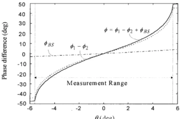
Substituting the latter experimental conditions, np5
1.51509, n5 3.57, and k 5 4.36, into Eqs. ~3!–~5! and ~8!, we can obtain the relation curves of f, ~f12 f2!,
andfBStou as shown in Fig. 3. It shows that in this
case the measurement range is between25.60° and 5.60°.
3. Experiments and Results
To show the feasibility of this technique, two right-angle prisms of BK7 glass with np 5 1.51509 and a
beam splitter with a chromium layer with n5 3.57 and k 5 4.36 are used, and they are mounted on a high-precision rotary stage~PS-u-90! with an angular resolution of 0.005° manufactured by Japan Chuo
Fig. 1. Schematic diagram for measuring small angles: PL, po-larizer; EOM, electro-optical modulator; AN, analyzer.
Fig. 2. Geometric relations betweenu and a1ora2.
Fig. 3. Calculated curves off versus u, ~f12 f2!, and fBS.
Precision Industrial Company Ltd. The heterodyne optical source10with a wavelength of 632.8 nm and
f5 2 kHz and a self-made phase meter with a
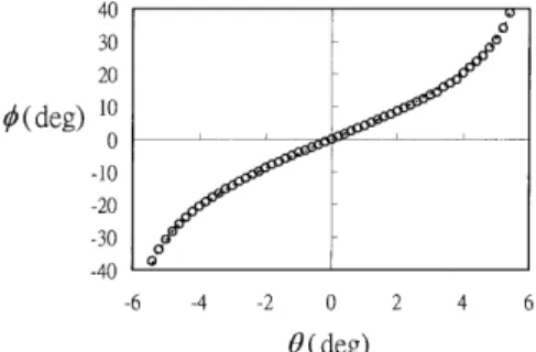
reso-lution of 0.01° are used. The experimental curves of f versus u for the angle measurement are shown in Fig. 4. In this figure, the circles represent the eval-uated values of the rotation angles, which are ob-tained by introducing the data off into Eqs. ~3!–~8!, and the dashed curve represents the direct angle readouts from the division mark of the rotary stage. It is clear that they have a good correspondence.
4. Discussion
From Eq. ~8!, we can obtain an expression for the measurement error:
Du 5 1
@df12 df2!ydu# 1 ~dfBS!ydu!
Df, (10) where Df is the angular resolution of the phase meter. In our experiments, the angular resolution of the phase meter is 0.01°. Consequently, the
rela-tion curve ofDu versus u can be obtained as shown in Fig. 5. Obviously, the error of the rotation angle becomes smaller asuuu increases; the best resolution is 8 3 1025° at uuu 5 5.6°. And the resolution of this technique is better than 1.6 3 1023° over the mea-surement range of25.60° # u # 5.60°.
Unlike many angle-measurement techniques, this approach is absolute: The phase difference is pre-cisely zero at zero angle. By using a higher-index glass, the angular range can be significantly ex-tended~e.g., for np5 1.8, umax' 20°!.
5. Conclusion
An improved technique for measuring small angles is proposed. Using heterodyne interferometry, it makes uses of the effect of total internal reflection in right-angle prisms as well as the phase-difference measurement between the two light beams passing through the prisms. This technique not only ex-pands the measurement range but also improves measurement performances. Its validity is demon-strated.
This study was supported in part by the National Science Council, Republic of China, under contract NSC85-2215-E-009-005.
References
1. J. Rohlin, “An interferometer for precision angle measure-ments,” Appl. Opt. 2, 762–763~1963!.
2. D. Malacara and O. Harris, “Interferometric measurement of angles,” Appl. Opt. 9, 1630 –1633~1970!.
3. G. D. Chapman, “Interferometric angular measurement,” Appl. Opt. 13, 1646 –1651~1974!.
4. P. Shi and E. Stijns, “New optical methods for measuring small-angle rotations,” Appl. Opt. 27, 4342– 4344~1988!. 5. P. Shi and E. Stijns, “Improving the linearity of the Mechelson
interferometric angular measurement by a parameter-compensation method,” Appl. Opt. 32, 44 –51~1993!. 6. A. E. Ennos and M. S. Virdee, “High accuracy profile
measure-ment of quasi-conical mirror surface by laser autocollimation,” Precis. Eng. 5, 5– 8~1982!.
7. G. G. Luther and R. D. Deslattes, “Single-axis photoelectronic autocollimator,” Rev. Sci. Instrum. 55, 747–750~1984!. 8. P. S. Huang, S. Kiyono, and O. Kamada, “Angle measurement
based on the internal-reflection effect: a new method,” Appl. Opt. 31, 6047– 6055~1992!.
9. P. S. Huang and J. Ni, “Angle measurement based on the internal-reflection effect and the use of right-angle prisms,” Appl. Opt. 34, 4976 – 4981~1995!.
10. D. C. Su, M. H. Chiu, and C. D. Chen, “Simple two-frequency laser,” Precis. Eng. 18, 161–163~1996!.
11. M. Born and E. Wolf, Principles of Optics, 6th ed.~Pergamon, Oxford, UK, 1980!, pp. 48–50.
Fig. 5. Relation curves ofDu versus u. Fig. 4. Experimental curves off versus u.