A Decoupling Technique for Increasing the Port
Isolation Between Two Strongly Coupled Antennas
Shin-Chang Chen, Yu-Shin Wang, and Shyh-Jong Chung, Senior Member, IEEE
Abstract—A compact decoupling network for enhancing the port isolation between two closely spaced antennas is proposed in this paper. In the network, we first connect two transmission lines (TLs) individually to the input ports of two strongly coupled antennas. The length of the TLs is designed so that the trans-admittance be-tween ports changes from a complex one at the antenna inputs to a pure imaginary one. A shunt reactive component is then attached in between the TL ends to cancel the resultant imaginary trans-ad-mittance. Finally, a simple lumped-element circuit is added to each port for input impedance matching. The even-odd mode analysis is adopted to investigate the currents excited on the antennas for predicting the radiation pattern of the two-element antenna array. Two examples of printed antennas at 2.45 GHz are tackled by using the proposed decoupling structure. The measurement results agree quite well with the simulation ones. High antenna isolation and good input return loss are simultaneously achieved in both cases, which demonstrates the feasibility of the structure. The decoupled antenna array in each example radiates, as prediction, toward dif-ferent but complementary directions when the input power is fed in turn to the two input ports. The array efficiency is estimated better than 75% in each example. This pattern diversity effect is helpful for reducing the channel correlation in a multiple-input multiple-output (MIMO) communication system.
Index Terms—Decoupling network, high isolation antennas, multiple-input multiple output (MIMO), pattern diversity, wire-less local area network (WLAN).
I. INTRODUCTION
F
UTURE wireless communication systems should be ca-pable of accommodating higher data rates than the cur-rent systems owing to the advent of various multimedia ser-vices. The use of multielement antennas, such as multiple-input multiple-output (MIMO) antenna systems, is one of the effec-tive ways for improving reliability and increasing the channel capacity. However, it is very difficult to integrate multiple an-tennas closely in a small and compact mobile handset while maintaining good isolation between antenna elements since the antennas couple strongly to each other and to the ground plane by sharing the surface currents on them.For a MIMO communication system, the data throughput can be pushed up to times, , that of a single-input single-output (SISO) system, as long as
Manuscript received November 14, 2007; revised April 29, 2008. Current version published December 30, 2008. This work was supported in part by the National Science Council, R.O.C., under Contract NSC 96-2752-E-009-003-PAE.
The authors are with the Department of Communication Engineering, Na-tional Chiao Tung University, Hsinchu, Taiwan (e-mail: [email protected]. tw).
Digital Object Identifier 10.1109/TAP.2008.2005469
the communication channels linked between the transmitter and the receiver are uncorrelated [1]–[3]. The correlation between the channels depends not only on the propagation environment, e.g., multipath effect due to the reflection and diffraction of outdoor buildings or indoor partitions, and also on the coupling between the or antennas. High antenna coupling (or low isolation) would introduce signal leakage from one antenna to another, thus increasing the signal correlation between the channels. It will also decrease the antenna radiation efficiency due to the loss of the power dissipated in the coupled antenna port. The signal correlation between two receiver antennas can be reduced by increasing the antenna spacing. However, this spacing is usually limited, especially for a mobile terminal which has very restricted volume for the antennas. The other way to diminish the correlation is using multiple antennas with different radiation patterns. It is better to have the patterns com-plementary to each other in space, so as to receive multipath signals from various directions.
For a long time, many papers have been focused on dimin-ishing the coupling of antennas. In [4], the relation of the iso-lation and the arrangement of two nearby antennas with dif-ferent operating bands in a cellular handset were studied. Itoh and the co-workers used the defected ground structure (DGS) to increase the port isolation of dual-polarized and dual-frequency patch antennas [5]. The above tackled the isolation problems of antennas operating at different frequencies. For decoupling two nearby antennas with the same frequency, many efforts have been done by using the electromagnetic band gap (EBG) struc-tures. Mushroom-like EBG structures are the ones that are usu-ally inserted between patch antennas to prevent the propagation of surface waves for higher isolation and better radiation pat-terns [6]–[8]. These EBG structures provide conspicuous de-coupling effect, but suffer from complicated structures and large structure area. Possible loss may also be induced in the resonant EBG structures. To reduce the coupling between two planar in-verted F antennas (PIFAs), Diallo [9]–[12] used a suspended metal strip linking the two antennas to cancel the reactive cou-pling between antennas. This neutralization technique has been also extended to patch antennas by Ranvier [13]. In [14], a de-coupling circuit network was realized for two-element array by using external transmission lines. Although good isolation was achieved, only weak coupled antennas were tackled. The all-transmission-lines configuration also made the circuit bulky. A similar approach of connecting circuits between elements has also been used to improve the impedance matching of a phased-array antenna over wide scan angles [15] since mutual coupling may vary the input impedance in different scanning angle. The mutual coupling of two closely packed antennas was reduced by
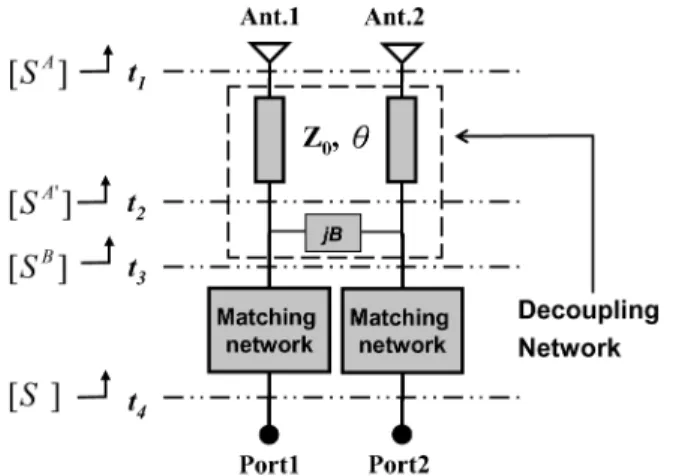
Fig. 1. The function blocks of the proposed decoupling structure, including two transmission lines, a shunt reactive component, and two impedance matching networks.
etching slots on the ground plane [16]. The fish-bone like slots formed equivalent inductors and capacitors on the ground plane, which prevented the flowing of the coupling ground current be-tween the antennas. A large ground plane size was needed for sufficient isolation.
In this paper, we propose a miniaturization structure to achieve high port isolation between two antennas. In Section II, the theory of the proposed decoupling structure is presented. The required parameters of the structure are derived based on the measured or simulated coupling coefficient between antennas. In Section III, for predicting the radiation patterns of the coupled antennas, the even-odd mode method is used to an-alyze the currents excited on the antennas after the embedding of the decoupling network. In Section IV, as applications of the proposed structure, two nearby printed monopole antennas for IEEE 802.11b/g WLAN (2.4 to 2.484 GHz) applications are designed and demonstrated with high isolation and good return loss. Section V gives the conclusions.
II. DECOUPLINGTHEORY
It is usually easy to design the input impedances but hard to reduce the coupling between two closely spaced antennas. In this study, a dual antenna system (Ant.1 and Ant. 2 in Fig. 1) with good input impedance matching but poor port isolation is first assumed. For simplicity, the antennas are symmetrical to each other and have input impedance of . A four-port decoupling network is proposed, with two output ports connected to the antennas, for reducing the coupling between the two resultant new input ports. Each input port is in turn connected to a matching network for improving the input impedance. Fig. 1 shows the function blocks of the decoupling structure.
The decoupling network consists of two transmission lines with characteristic impedance and electrical length and a shunt reactive component with admittance . Let the scat-tering matrix of the coupled antennas be denoted as at the reference plane . After connecting the transmission lines, the new scattering matrix at the reference plane is expressed as
. is the scattering matrix at the reference plane after the addition of the shunt lumped element. Finally, the total scat-tering matrix at the reference plane , including the antennas, the decoupling network, and the matching networks, is indicated as [S].
Since the coupled antennas are assumed with good input matching, the diagonal terms of approximately vanish, and the scattering matrix at can thus be expressed as
(1) where and are the magnitude and phase of the coupling co-efficient between antennas. After adding a transmission line of the same impedance to each antenna port, the return loss re-mains infinite (or, ), while the coupling coefficient ex-periences an extra phase delay of 2. Thus, the scattering matrix at can be described as
(2) Once this scattering matrix is known, the corresponding ad-mittance matrix can be easily derived [17].
As shown in Fig. 1, the two-port network seen at is in shunt with a reactive element of susceptance , and thus the resultant new two-port network, i.e., that with ports at , should have an admittance matrix equal to
(3) where is the admittance matrix of the two-port network composed of the shunt component
(4) Therefore, the components of can be derived as
(5) and
(6) The components of the scattering matrix at are related to these components through the following formulas [16]:
(7)
(8) where represents the characteristic admittance of the input
ports, .
Since our purpose is to eliminate the coupling of the two ports, the coupling coefficient at should be zero, which means that, from (7), the trans-admittance should vanish.
Then, from (5), the required electrical length and the suscep-tance can be solved
(9) and
(10) Both of these values are physically realizable, since both pos-itive and negative values of are possible (positive implies a capacitor and negative implies an inductor). However, a shunt capacitor is preferred, since a negative B corresponds to a neg-ative ( is negative due to close spacing between antennas), which means longer transmission lines (longer than half wave-length) are required.
The solution of (9) is quite obvious, which shows that the cou-pling coefficient after the introduction of the transmission lines should possess a phase equal to . As revealed in (5), when this condition holds, the trans-admittance at would be pure imaginary, and can thus be cancelled by the reac-tive component . The transmission lines have the functions of not only delay lines of connecting the antenna input ports to the decoupling network, but also transferring the complex trans-ad-mittance at the coupled antennas to a pure imaginary one.
The solutions of (9) and (10) can be cast into (6) to get the input admittances and at . Further impedance matching network is required to transfer these input admittances to the system admittance . A simple L-section matching net-work, which uses a series and a shunt reactive element, can usually accomplish the requirement.
III. DERIVATION OFANTENNADRIVINGCURRENTS
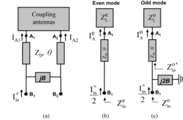
Due to the close coupling between the two antennas and the introduction of the decoupling network, both the antennas will be excited even if the input power is only fed to one port. The an-tennas form a two-element array, with the radiation pattern de-termined by the excited currents on the antennas. Consider now that port 1 is fed by a current source and port 2 is terminated by . Let the input current, after passing the impedance matching network, at the reference plane [or point of Fig. 2(a)] be denoted as . Note that since at point the impedance is not matched, this input current would cause a returning cur-rent propagating back to the impedance matching network. In order to estimate the radiation pattern, the resultant driving cur-rents and at the input points (points and ) of the two coupled antennas are to be derived through the even and odd modes analysis [16]. To this end, the two-port cou-pled antennas are first modeled by a T network. Then, by set-ting the connecset-ting points at the symmetric plane as open-cir-cuits for the even mode and short-ciropen-cir-cuits for the odd mode, the even-mode and odd-mode circuit schematics can be obtained as shown in Fig. 2(b) and (c), respectively. The even-mode
Fig. 2. (a) The coupled antennas in connection with the decoupling network. (b) The corresponding even-mode circuit. (c) The odd-mode circuit.
and odd-mode antenna load impedances at point are derived as
(11) (12) with , , 2, being the components of the impedance matrix of the coupled antennas, which can be obtained from the scattering matrix [16]. And the corresponding reflection coefficients at the antenna input points are
(13) (14) After a simple derivation, the even-mode driving current at point can be expressed as
(15) Similarly, the odd-mode driving current is expressed as
(16) where
(17) and and are the reflection coefficients at point for the even mode and odd mode, respectively. When the two system ports are perfectly isolated, the input impedances at point of the even mode and odd mode should be the same, which can be easily derived by modeling the two-port network shown in Fig. 2(a) as a network, and
The corresponding reflection coefficients and in (15) and (16) are thus equal to each other.
Finally, by casting (13) and (14) into (15) and (16), and using the relationships of (9), (10), and (18), the ratio of driving cur-rents at the antenna input points can be derived as a function of the coupling coefficient
(19)
IV. EXAMPLES
Two examples are tackled in this study. One is a dual-antenna system with two closely spaced parallel printed monopole an-tennas, and the other is with two miniaturized printed antennas. The antennas, operating at the frequency of 2.45 GHz, were all implemented on the FR4 substrates with the dielectric constant of 4.5, the loss tangent of 0.02, and the thickness of 0.8 mm. Both the EM simulator HFSS [18] and the circuit simulator AWR Microwave Office [19] were used for the simulation. The former handles the full-wave simulation for the antenna struc-ture, with the results cast to the latter, if needed, for the following lumped-element related simulation.
A. Two Closely Spaced Printed Monopole Antennas
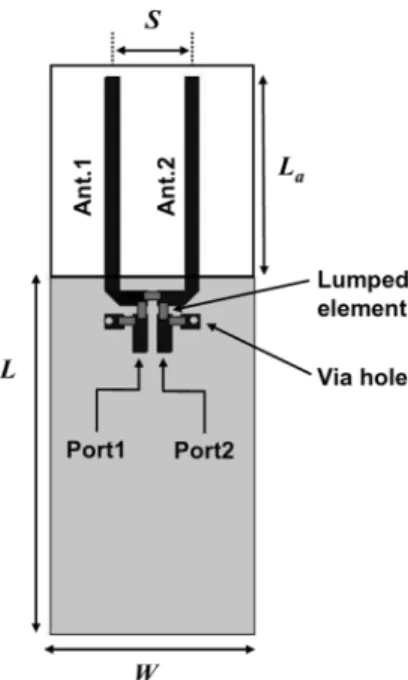
The first example is two parallel printed monopole an-tennas with length and spacing (0.069 at 2.45 GHz), as shown in Fig. 3. The antennas are fed by two 50 microstrip lines of width 1.5 mm on a substrate with
ground size of , which is suitable
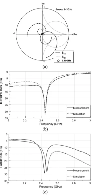
for a general USB dongle. By using the full-wave simulator HFSS, the antenna dimensions are first designed to be with length and metal strip width of 1.5 mm for good input impedance matching. Fig. 4(a) plots the results of simulated S-parameters from 2 to 3 GHz for the two coupled antennas in the complex plane. It is seen that at this stage, the reflection coefficient (and ) is close to the origin of the coordinate around the center frequency, but the coupling coeffi-cient is not. This means that the two antennas exhibit input impedances close to 50 while have poor isolation between them. The coupling coefficient at 2.45 GHz is with an amplitude and a phase . Fig. 4(b) and (c) depicts, respectively, the return loss and the isolation as functions of the frequency. Both the simulation and measurement results are shown, which show good agreement with each other. The measured 10-dB return-loss bandwidth is 15.1% from 2.27 to 2.64 GHz and the worst isolation in the in-band (from 2.4 to about 2.5 GHz) is only 3 dB.
According to the proposed structure in Fig. 1, the decoupling network was added after the two coupled antennas to increase the isolation between input ports. The required transmis-sion-line length and the shunt susceptance can be obtained by setting and into (9) and (10), leading
to and (or a capacitance of 1.26 pF).
In practice, a 1-pF Murata SMD capacitor with number of GRM1555C1H1R0CZ0 [20] was used. The high-frequency parasitics of the capacitor and the solders make the susceptance
Fig. 3. The configuration of the two closely spaced printed monopole antennas.
of this capacitor meet the requirement. The resultant S-param-eters, return loss, and isolation are illustrated in Fig. 5. It is seen that the curve of the coupling coefficient shown in Fig. 5(a) goes very close to the coordinate origin near the center frequency. The port isolation at 2.45 GHz becomes 35 dB as shown in Fig. 5(c). There is at least 30 dB improvement of isolation after the decoupling network is employed. However, this improvement of the isolation is obtained at the expense of deteriorating the input matching. As can be observed from Fig. 5(a) and (b), the impedance matched frequency shifts from 2.45 GHz to a lower one (2.36 GHz). The measured return loss at 2.45 GHz is only 3 dB. Further matching network is thus necessary in this situation. Since the isolation is very high ( almost zero), the additional impedance matching network will not change the isolation and the individual return loss, at least near the center frequency. A simple L-section matching network, with a series inductor (4.7/5.1 nH, Murata LQG15HN4N7S02/ LQG15HN5N1S02) and a shunt capacitor (1 pF, Murata GRM1555C1H1R0CZ0) [19], is adopted at each input port to pull back the matched frequency to 2.45 GHz. Note that due to the experiment tolerance, the inductors used in the two ports are little different after fine tuning.
The final results for the antennas with the decoupling network and the matching network are depicted in Fig. 6. Both the curves for the reflection coefficient and the coupling coefficient shown in Fig. 6(a) go near the origin at the center fre-quency. The measured 10-dB return-loss bandwidth covers at least from 2 GHz up to 2.51 GHz, with a maximum return loss of 28 dB at 2.45 GHz. The best measurement isolation happens at 2.44 GHz and reaches a level of 30 dB. From 2.4 to 2.5 GHz, the isolation has been improved to be better than 10 dB. It is seen that the matching network ameliorates the return loss while re-mains the high isolation. The measurement results match quite well with the simulation ones.
Fig. 7 shows the measured radiation patterns in the three prin-cipal planes of the finished high-isolation antennas, with port 1
Fig. 4. (a) The simulated reflection coefficientS and coupling coefficient S , in the complex plane, of the strongly coupled monopole antennas. (b) Mea-sured and simulated return losses. (c) MeaMea-sured and simulated isolations.
excited and port 2 terminated to a 50- load. Although only port 1 is driven, both antennas are distributed with currents due to the presence of the decoupling network and the strong near-field coupling between antennas. The ratio of currents induced on the two monopoles can be estimated through the result derived in the previous section. By inserting and into
(19), one obtains . The distance
be-tween the two antennas is 8.5 mm, which corresponds to a wave propagation delay of about 25 at 2.45 GHz. Thus, the phase difference of the excited antenna currents would cause
an out-of-phase far-field cancellation
in the direction, resulting in a radiation pattern directed to-ward the negative direction as shown in Fig. 7. The measured peak gains are respectively 1.8 dBi in the plane,
in the - plane, and in the - plane. Although not shown here, the measured radiation patterns when fed from port
Fig. 5. (a) The simulated reflection coefficientS and coupling coefficient S , in the complex plane, of the coupling monopole antennas with decoupling network. (b) Measured and simulated return losses. (c) Measured and simulated isolations.
2 are similar to those in Fig. 7, but with the beam directed to the opposite direction (i.e., positive direction). It should be mentioned that due to the induction of the ground plane cur-rent, the radiation patterns shown in the figure are different from those calculated using the two-element array theory. However, the measured pattern diversity effect does coincide with the the-oretical prediction. The proposed antenna decoupling structure provides two complementary diversity patterns when the two antenna ports are fed separately, which is thus quite suitable for the application in a MIMO system with prosperous multiple signal paths.
It is interesting to evaluate the efficiency of the whole an-tenna system after the use of the decoupling network. To this end, the radiation patterns of two extra antennas are measured and compared to the present example. The first is a single printed monopole antenna and the second is two closely spaced printed monopole antennas without decoupling. Both the antennas have
Fig. 6. (a) The simulated reflection coefficientS and coupling coefficient S , in the complex plane, of the coupling monopole antennas with decoupling network and impedance matching networks. (b) Measured and simulated return losses. (c) Measured and simulated isolations.
the same ground size and monopole strip size as the present example. Fig. 8 shows the measured radiation patterns in the - plane for the two antennas. In the measurement, the single monopole antenna is first matched by a series inductor (2.2 nH) for good return loss at the center frequency. And the coupled an-tennas without decoupling, whose return loss and isolation are shown in Fig. 4, is fed from port 1 with port 2 terminated. It is seen that the single printed antenna has a typical donut-like
Fig. 7. Measured radiation patterns of the two closely spaced printed monopole antennas at 2.45 GHz when fed from port 1. (a)x-y plane. (b) x-z plane. (c) y-z plane.
pattern with peak gain of . The strongly coupled an-tennas without decoupling also exhibit a near donut-like pat-tern but tilted due to the presence of the terminated monopole. Since half of the input power is absorbed in port 2, the radia-tion peak gain is only as shown in Fig. 8(b), about 3 dB lower than that of the single antenna. It is evident that the decoupled antennas in this example with measured peak gain of 1.8 dBi [Fig. 7(a)] possess an antenna gain 2.1 dB higher than the single monopole antenna. Therefore, the array effi-ciency is approximately 80% based on the maximum array gain of 3 dB for two-element array. Notably, this efficiency includes that of the matching circuit. According to the Murata’s library, the matching efficiency is 93% when using L-type matching with a series 4.7 nH inductor and a shunt 1 pF capacitor.
B. Two Miniaturized Printed Antennas
For practical application, the antennas in the previous ex-ample occupy too much antenna area and need to be miniatur-ized. Fig. 9 illustrates the miniaturized version of the printed monopole antennas, which are fabricated on the same FR4
sub-strate with the same ground size .
The antenna dimensions are designed as ,
, , (0.040 at 2.45 GHz), and
to have good input matching. The simulated cou-pling coefficient at the center frequency is with an amplitude of and phase of . Strong coupling still appears between these two miniaturized antennas. According to the de-coupling solutions in (9) and (10), the required transmission line
Fig. 8. Measured radiation patterns(E ) in the x-y plane of (a) the single printed monopole antenna. (b) The two closely spaced printed monopole an-tennas without decoupling.f = 2:45 GHz.
a capacitance of 1 pF) were obtained. A shorter length of trans-mission lines and smaller capacitance are needed than those in the previous examples. For the impedance matching network, only a series inductor (4.3 nH) was adopted in each port. No shunt component was used in the practical implementation due to the lack of available capacitors with very small capacitances.
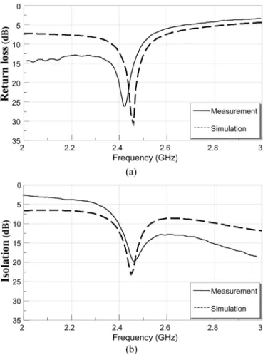
The resultant return losses and isolations are shown in Fig. 10(a) and (b), respectively. It is seen that the simulation return loss and isolation are better than 10 dB in the in-band with deeps at the design center frequency (2.45 GHz). And the measurement results follow the simulation ones quite well. The deep of the measured return loss happens at a lower frequency (2.42 GHz) as shown in Fig. 10(a), owing to the omitting of the small shunt capacitance in the impedance matching network. However, the return loss still keeps higher than 10 dB in the frequency range from 2.4 to 2.5 GHz, with a maximum value of 27 dB at 2.42 GHz. On the other hand, the measured isolation curve shifts a little bit toward the higher frequency as depicted in Fig. 10(b). The isolation is larger than 10 dB for frequencies higher than 2.4 GHz. A maximum isolation value of 20 dB was measured at the frequency of 2.46 GHz.
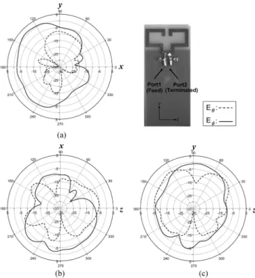
Fig. 11 illustrates the measured radiation patterns with port 1 excited and port 2 terminated to a 50- load. Like those of the parallel straight monopole antennas, the radiation pattern of the miniaturized antennas directed toward the negative direc-tion with measured peak gains of 1.57 dBi in the - plane,
Fig. 9. The configuration of the two closely spaced miniaturized monopole antennas.
Fig. 10. (a) The return loss. (b) The isolation of the miniaturized monopole antennas with decoupling network and impedance matching networks.
in the - plane, and in the - plane. The pattern changes to the positive direction when the input power is fed from port 2. Following the discussion in the previous ex-ample, the array efficiency, as compared to a straight monopole antenna, is about 75%.
Fig. 11. Measured radiation patterns of the two closely spaced miniaturized monopole antennas at 2.45 GHz when fed from port 1. (a)x-y plane. (b) x-z plane. (c)y-z plane.
V. CONCLUSION
In this paper, a decoupling technique using the circuit ap-proach for improving the isolation between two closely spaced antennas of the same frequency has been proposed. The decou-pling circuit is simple and compact, which contains two trans-mission lines and a shunt reactive component, followed by a simple L-section (or –section) impedance matching network at each port. Two examples of strongly coupled antennas were suc-cessfully handled. The isolations between antennas were greatly improved from 3 dB to more than 20 dB at the center frequency while the input return losses remained better than 10 dB. The measurement results matched quite well with the simulation ones.
An analysis tackling the excitation currents on the antennas was done for the prediction of the radiation pattern of the two-el-ement array. The predicted results revealed that, the radiation pattern directed toward one side when the power was fed to one port, while toward the other side when fed to the other port. The measured radiation patterns coincided with this prediction. The proposed antenna decoupling structure provides two comple-mentary diversity patterns when the two antenna ports are fed separately, which is quite suitable for the application in a MIMO system with prosperous multiple signal paths.
The simple circuitry and the compact size of the proposed decoupling structure make it practical to be applied in a ter-minal communication device. The developed port isolation tech-nique can be used in various areas such as MIMO antennas, two closely positioned antennas of different systems like Wi-Fi and Bluetooth, or the decoupling between transmitting and receiving antennas.
REFERENCES
[1] A. J. Paulraj et al., “An overview of MIMO communications—A key to gigabit wireless,” Proc. IEEE, vol. 92, no. 2, pp. 198–218, Feb. 2004. [2] G. J. Foschini and M. J. Gans, “On limits of wireless communications
in a fading environment when using multiple antennas,” Wireless Pers.
Commun., vol. 6, no. 3, pp. 331–335, 1998.
[3] T. Hult and A. Mohammed, “Compact MIMO antennas and hap diver-sity for data rate communications,” in Proc. Veh. Technol. Conf., Apr. 2007, pp. 1385–1389.
[4] Z. Li and Y. R. Samii, “Optimization of PIFA-IFA combination in handset antenna design,” IEEE Trans. Antennas Propag., vol. 53, no. 5, pp. 1770–1778, May 2006.
[5] Y. Chung, S. S. Jeon, D. Ahn, J. I. Choi, and T. Itoh, “High isolation dual-polarized patch antenna using integrated defected ground struc-ture,” IEEE Microw. Wireless Comput. Lett., vol. 14, no. 1, pp. 4–6, Jan. 2004.
[6] F. Yang and Y. R. Samii, “Microstrip antennas integrated with electro-magnetic band-gap EBG structures: A low mutual coupling design for array applications,” IEEE Trans. Antennas Propag., vol. 51, no. 10, pp. 2936–2946, Oct. 2003.
[7] Z. Iluz, R. Shavit, and R. Bauer, “Microstrip antenna phased array with electromagnetic bandgap substrate,” IEEE Trans. Antennas Propag., vol. 52, no. 6, pp. 1446–1453, Jun. 2004.
[8] L. Yang, M. Fan, F. Chen, J. She, and Z. Feng, “A novel compact electromagnetic-bandgap (EBG) structre and its applications for mi-crowave circuits,” IEEE Trans. Microw. Theory Tech., vol. 53, no. 1, pp. 183–190, Jan. 2005.
[9] A. Diallo, C. Luxey, P. L. Thuc, R. Staraj, and G. Kossiavas, “Study and reduction of the mutual coupling between two mobile phone PIFAs operating in the DCS1800and UMTS bands,” IEEE Trans. Antennas
Propag., vol. 54, no. 11, pp. 3063–3073, Nov. 2006.
[10] A. Diallo, C. Luxey, P. L. Thuc, R. Staraj, G. Kossiavas, M. Franzen, and P.-S. Kildal, “MIMO performance of enhanced UMTS four-an-tenna structures for mobile phones in the presence of the user’s head,” in Proc. IEEE AP-S Int. Symp., Jun. 2007, pp. 2853–2856.
[11] A. Diallo and C. Luxey, “Estimation of the diversity performance of several two-antenna systems in different propagation environments,” in Proc. IEEE AP-S Int. Symp., Jun. 2007, pp. 2642–2645.
[12] A. Diallo, C. Luxey, P. L. Thuc, R. Staraj, and G. Kossiavas, “En-hanced two-antenna structures for universal mobile telecommunica-tions system diversity terminals,” IET Microw., Antennas Propag., vol. 2, no. 1, pp. 93–101, Feb. 2008.
[13] S. Ranvier, C. Luxey, P. Suvikunnas, R. Staraj, and P. Vainikainen, “Capacity enhancement by increasing both mutual coupling and effi-ciency: A novel approach,” in Proc. IEEE AP-Symp. 2007, Honolulu, HI, Jun. 2007.
[14] J. Andersen and H. Rasmussen, “Decoupling and descattering net-works for antennas,” IEEE Trans. Antennas Propag., vol. 24, pp. 841–846, Nov. 1976.
[15] P. W. Hanna, D. S. Lerner, and G. H. Knittel, “Impedance matching a phased-array antenna over wide scan angles by connecting circuits,”
IEEE Trans. Antennas Propag, vol. 13, no. 1, pp. 28–34, Jan. 1965.
[16] C. Y. Chiu, C. H. Cheng, R. D. Murch, and C. R. Rowell, “Reduction of mutual coupling between closely-packed antenna element,” IEEE
Trans. Antennas Propag., vol. 55, no. 6, pp. 1732–1738, Jun. 2007.
[17] D. M. Pozar, Microwave Engineering, 3nd ed. New York: Wiley, 2005.
[18] HFSS Ansoft Corp. 2005, ver.10.0.
[19] Microwave Office Appl. Wave Res. Inc, El Segundo, CA, 2007. [20] Murata Manufacturing Co., Ltd. [Online]. Available: http://www.
murata.com)
Shin-Chang Chen was born in February 1983 in
Taipei, Taiwan, R.O.C. He received the B.S. degree in electronic engineering from the National Taipei University of Technology (NTUT), Taipei, Taiwan, in 2005, and the M.S. degree in communication en-gineering from the National Chiao Tung University (NCTU), Hsinchu, Taiwan.
His research interests are microwave circuits and antennas.
Yu-Shin Wang was born in May 1981 in Taichung,
Taiwan, R.O.C. He received the B.S. degree in communication engineering from the National Chiao Tung University, Hsinchu, Taiwan, in 2003.
He is currently working toward the Ph.D. degree in communication engineering at the same university. His research interests are microwave circuits, minia-ture antennas, and antenna arrays.
Shyh-Jong Chung (M’92–SM’06) was born in
Taipei, Taiwan, R.O.C. He received the B.S.E.E. and Ph.D. degrees from National Taiwan University, Taipei, Taiwan, in 1984 and 1988, respectively.
Since 1988, he has been with the Department of Communication Engineering, National Chiao Tung University, Hsinchu, Taiwan, where he is currently a Professor. From September 1995 to August 1996, he was a Visiting Scholar with the Department of Elec-trical Engineering, Texas A&M University, College Station. He has authored or coauthored more than 70 technical papers in international journals or conferences including several in-vited papers and speeches. His areas of interest include the design and applica-tions of active and passive planar antennas, communicaapplica-tions in intelligent trans-portation systems (ITSs), LTCC-based RF components and modules, packaging effects of microwave circuits, and numerical techniques in electromagnetics.
Dr. Chung serves as the Chairman of IEEE MTT-S Taipei Chapter from 2005. He was also the Treasurer of the IEEE Taipei Section from 2001 to 2003.