國 立 交 通 大 學
電信工程學系
碩 士 論 文
IEEE 802.16h 系統下使用乏晰有效週期
調整之動態頻譜擷取
Fuzzy Active Period Adaptation for
Dynamic Spectrum Access in IEEE
802.16h System
研 究 生:孫浩翔
指導教授:張仲儒 博士
IEEE 802.16h 系統下使用乏晰有效週期調整之動態
頻譜擷取
Fuzzy Active Period Adaptation for Dynamic Spectrum
Access in IEEE 802.16h System
研 究 生:孫浩翔 Student:Hao-Hsiang Sun
指導教授:張仲儒 博士 Advisor:Dr. Chung-Ju Chang
國 立 交 通 大 學
電信工程學系
碩 士 論 文
A Thesis
Submitted to Department of Communication Engineering
College of Electrical and Computer Engineering
National Chiao Tung University
in Partial Fulfillment of the Requirements
for the Degree of Master of Science
in
Communication Engineering
July 2008
Hsinchu, Taiwan
中華民國九十七年七月
IEEE 802.16h 系統下使用乏晰有效週期調整之動態
頻譜擷取
研究生:孫浩翔 指導教授:張仲儒 博士
國立交通大學電信工程學系碩士班
Mandarin Abstract
摘 要 由於科技的日益進步,無線通訊服務的需求量也逐漸增加,而其傳輸所需要 頻寬也越來越珍貴,因此我們必須在這有限的頻寬資源中尋找出更有效的頻寬利 用方法。近年來,隨著感知無線電(Cognitive Radio, CR)之提出,我們將其視 為一個可以有效的使用頻寬的重要技術。 在本篇論文中,我們採用了 IEEE 802.16h 的機制來做空閒頻譜偵測,並且 設計了一個乏晰有效週期調整器(Fuzzy Active Period Adaptor)來有效利用 我們所偵測到的空閒頻譜。其主要目的是在固定頻段中提升系統整體的效能。 在 提 出 的 演 算 法 中 , 我 們 主 要 是 以 WLAN 為 現 行 運 行 系 統 的 免 執 照 頻 譜 (Unlicensed Band)為主要感測之頻譜,而 WiMAX 系統將使用感知無線電技術來 作免執照頻段的動態頻譜擷取(Dynamic Spectrum Access)之動作。從模擬的結果中,我們所提出的方法可以有效且合理的去使用所偵測到的空 閒頻譜,在盡量減少干擾 WLAN 系統運作之前提下,有效的提升整體傳輸量並且 減少頻譜的閒置資源。
Fuzzy Active Period Adaptation for Dynamic
Spectrum Access in IEEE 802.16h System
Student: Hao-Hsiang Sun Advisor: Dr. Chung-Ju Chang
Department of Communication Engineering
National Chiao Tung University
English Abstract
Abstract
With the development of communication technology, wireless communications become more important to provide convenient services. It triggers a huge demand for bandwidth for transmission. Because of the spectrum scarcity, how to use the spectrum dynamically and efficiently becomes an important issue.
Dynamic spectrum access (DSA) is a promising approach to alleviate the spectrum scarcity that wireless communications face today. To provide the mechanism of DSA networks, the use of “cognitive radio” (CR) technology is viewed as the key technology to fully utilize the bandwidth. In this thesis, a CR-based dynamic spectrum access (DSA) device named fuzzy active period adaptor (FAPA) is proposed in downlink transmission of IEEE 802.16h systems. FAPA decides the active period of CR system to efficiently coexist with WLAN system in 802.16h system. Simulation results show the fuzzy active period adaptation can improve the overall throughput and reduce the idle time of the spectrum with slightly interfering in the operation of the primary WLAN system.
誌 謝
Acknowledgements
能夠順利完成這篇論文,我必須感謝許多人給予我支持與幫助。首先我必須 感謝我的指導教授張仲儒博士,不論在專業領域以及待人處世方面,都給予我許 多的提點與指引,再來則是感謝在百忙之中還抽空來指導我的芳慶學長,犧牲自 己的時間解答我所有的疑惑。感謝志明、耀興、文祥、詠翰、和立峰學長適時的 幫助和建議,讓我能更快地去解決我所遇到的問題;感謝建安、世宏、建興、佳 泓、佳璇、正昕以及尚樺,親切的帶領我進入實驗室這個可愛的大家庭;感謝這 兩年一起走來的邱胤、宗利、英奇、維謙以及巧瑩,由於你們的鼓勵與樂觀的想 法,給予了我繼續前進的勇氣;感謝和儁、盈伃、欣毅、志遠、玉棋以及惟媜, 你們讓實驗室變得更熱鬧與溫暖,讓研究生的生活增添了不少色彩,在這也祝福 你們未來的生活一帆風順。 最後,我要感謝我最愛的父母、家人以及女朋友孟儒,你們的支持、關心與 鼓勵我的的確確收到了,也因為你們默默的支持,我才能順利且沒有負擔的走過 這兩年研究生生涯。 浩翔 謹誌 民國 九十七年七月Contents
Mandarin Abstract ...i
English Abstract...ii
Acknowledgement ... iii
Contents ...iv
List of Figures...v
List of Tables ...vi
Chapter 1 Introduction...1
Chapter 2 Dynamic Spectrum Access in 802.16h ...7
2.1 Dynamic Spectrum Access: White Space Detection ...7
Chapter 3 System Model ... 11
3.1 WiMAX System...12
3.2 WLAN System...13
3.3 CR System ...14
Chapter 4 Active Period Adaptation by Fuzzy Logic Theory ...16
4.1 Membership Function and Fuzzy Rule Base ...19
4.2 Defuzzification...28
Chapter 5 Simulation Results and Discussion...30
5.1 Scenario...31
5.2 Source Traffic Model of WLAN System...32
5.3 Performance Evaluation...33
Chapter 6 Conclusions...40
List of Figures
Fig. 1.1: White space (Spectrum hole) concept ...3
Fig. 2.1: The LBT protocol ...8
Fig. 2.2: The EQP protocol ...8
Fig. 2.3: The LBT+EQP protocol ...9
Fig. 2.4: The flow chart of white space detection...10
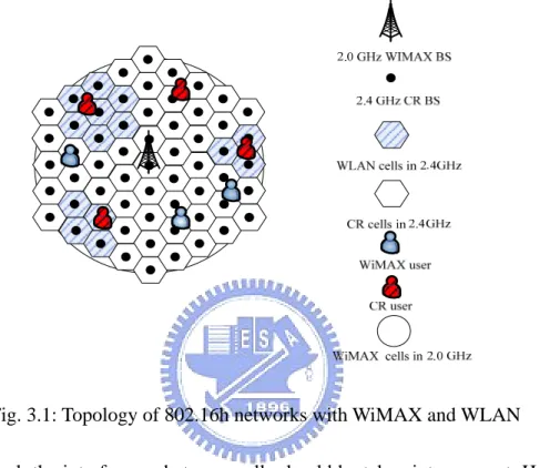
Fig. 3.1: Topology of 802.16h networks with WiMAX and WLAN ...12
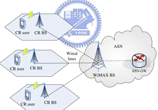
Fig. 3.2: Infrastructure of CR systems ...15
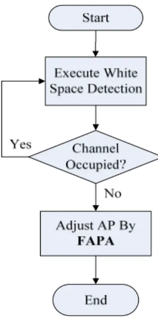
Fig. 4.1: CR-based dynamic spectrum access algorithm ...17
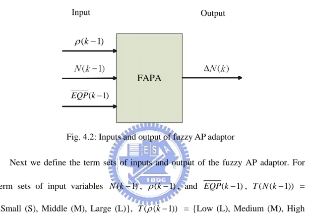
Fig. 4.2: Inputs and output of fuzzy AP adaptor ...19
Fig. 4.3: Definitions for (a) function g( )⋅ and (b) function f( )⋅ ...20
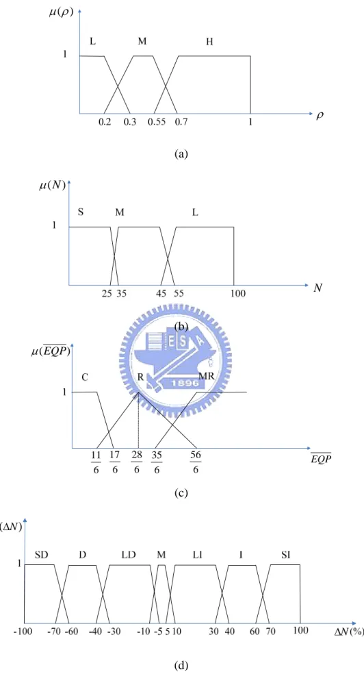
Fig. 4.4: Membership functions for terms of (a) ρ, (b) N, (c) EQP , and (d) ΔN ...25
Fig. 4.5: Collision probability in WLAN system...26
Fig. 4.6: Average WLAN packet delay ...27
Fig. 4.7: Procedure of max-min method for defuzzification ...29
Fig. 5.1: Simulation Scenario...32
Fig. 5.2: The proportion of idle time in unlicensed spectrum...35
Fig. 5.3: The individual CR system throughput...36
Fig. 5.4: The throughput of WLAN system ...37
List of Tables
Table 4.1: The rule base of fuzzy AP adaptor ...27
Table 5.1: Simulation Parameters for WLAN system...30
Table 5.2: Simulation Parameters for CR system ...31
Chapter 1
Introduction
In recent years, wireless communications become more important to provide convenient service and operations. Because of the extensive acceptance for the wireless communications, it triggers a huge demand for bandwidth. However, today’s wireless networks are regulated by a fixed spectrum assignment policy, i.e. spectrum is regulated by governmental agency and is assigned to license holders or services on a long term basis for large geographical regions. Generally speaking, this policy is inefficient.
How to use the licensed band dynamically and efficiently becomes an important issue. Dynamic spectrum access (DSA) is a promising approach to alleviate the spectrum scarcity that wireless communications face today. Its purpose is to fully utilize the unused radio source. By using the mechanism of DSA, secondary users can dynamically access and reuse the frequency bands occupied by primary users while causing no interference to the primary users. To provide the mechanism of DSA networks, cognitive radio (CR) technology is the key technology that empowers a next-generation (xG) network to use spectrum in a dynamic manner. The term, cognitive radio, can formally be defined as follows [1]: A ‘‘Cognitive Radio’’ is a radio that can change its transmitter parameters based on interaction with the
environment in which it operates.” IEEE 1900.1 defines CR as: “a radio in which communication systems are aware of their environment and internal state and can make decisions about their radio operating behavior based on that information and predefined objectives.” From those definitions, we can define two main characteristics of the cognitive radio [2]: cognitive capability and reconfigurability. Cognitive capability refers to the ability of the radio technology to capture or sense the information from its radio environment. This capability cannot simply be realized by monitoring the power in some frequency band of interest but more sophisticated techniques are required in order to capture the temporal and spatial variations in the radio environment and avoid interference to other users. Through this capability, the portions of the spectrum that are unused at a specific time or location can be identified. Consequently, the best spectrum and appropriate operating parameters can be selected. Reconfigurability refers to the cognitive capability that provides reconfigurability and it enables the radio to be dynamically programmed according to the radio environment. More specifically, the cognitive radio can be programmed to transmit and receive on a variety of frequencies and to use different transmission access technologies supported by its hardware design [3].
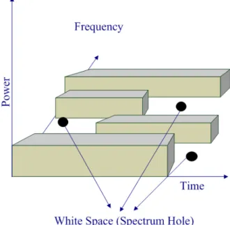
To date, a number of organizations has proposed methods which exploit cognitive radios to obtain higher spectral efficiency. Thus, the goal of the CR is to obtain and access the best available spectrum through its cognitive capability and reconfigurability. The CR user enables the usage of the spectrum called “white space (spectrum hole)” that is temporally unoccupied by the primary user. A definition for spectrum hole: “A spectrum hole is a band of frequencies assigned to a primary user, but, at a particular time and specific geographic location, the band is not being utilized by that user,” is offered in [2]. From Fig. 1.1, through the time, power and frequency
domains, we can briefly understand where and when the white space occurs. It shows that in time domain and frequency domain, there will be some white space unused by the primary user. In power domain, if the secondary user can transmit its signal by using the power that won’t interfere with the primary user, it would be regard as a white space. In [4], it briefly mentioned about the spectrum hole filling concept for CR. Thus, how to dynamically and opportunistically use the white space is an important topic for study.
Fig. 1.1: White space (Spectrum hole) concept
For the market-oriented approach, CR-based DSA will provide significant economic and social benefits if it is widely available and utilized. For this to occur, the wireless services market itself must evolve. So the market incentives, and ways of managing risk must develop around the new features of DSA radios. Through the CR-based DSA, we can gain a lot of profit by exploiting the market for the secondary users.
wireless networks in unlicensed band is very important. Srinivasa and Jafar proposed three solutions in broad sense of CR for the secondary user: overlay, underlay, or interweave [5]. Overlay and underlay is more likely the coexistence between primary and secondary users as an example illustrated in [6]. In my thesis, the interweave solution is mainly concerned. That is, there exist temporary frequency voids, referred to as spectrum holes, which are not in use by the primary owners. Only these empty spectrums can be used for communication by secondary users. Consequently, the utilization of the spectrum is improved by opportunistic frequency reuse over the spectrum holes.
So we can see there exists several key points that need to be investigated for the development of the spectrum sensing function: how to access the white space opportunistically and decide the holding time for the CR users. Holding time means the activities of primary users can affect the channel quality in xG networks. That is, holding time refers to the expected time duration that the secondary user can occupy a band before getting interrupted. Obviously, the longer the holding time, the higher the efficiency would be. Since the fairness should put into consideration, frequent spectrum handoff can decrease the holding time and maintain the fairness. So we have to strike a balance between fairness and efficiency.
The difficulty of white space detection lies in effectively measuring the channel usage by the primary users. And we have to use some mechanisms to coordinate the interaction between primary user and secondary user, such as Common Spectrum Coordination Channel (CSCC) [7]. However, currently, there exists no practical way for a cognitive radio to measure or estimate the white space and avoid the collision between primary user and CR user.
In IEEE 802.16h [8], it introduces the way of coexistence between IEEE Standard 802.16 system and IEEE 802.11 system. To do the white space access, it proposes two mechanisms called Listen-Before-Talk (LBT) and Extended Quiet Period (EQP). An active period (AP) is set to be the frames that can be used for secondary user. But the length of active period is undefined in IEEE 802.16h system and the white space usage of the secondary user is inefficient. In [9], the usage of white space is limited because it can’t adjust AP timely and efficiently. To improve the performance, we try to adjust active period by an effective and intelligent way.
Traditional modeling and computation techniques are not well-suited to fulfill the requirement of future mobile communication networks. So the intelligent technique such as fuzzy logic system has broadly used in the up-to-date communication systems. Fuzzy logic system is mimicked the operation of the human brain and built to help solving problems with vague information [10]. It has the capabilities of soft-computing and adaptation, which are more flexible for network designers to cope with the network control problems. Because of the advantages mentioned above, we will adopt fuzzy logic system to the adjustment of active period. Besides, we will compare our design of fuzzy logic system to the way that
From the survey of CR-based DSA and IEEE 802.16h, it is a good topic for research on how to use the spectrum efficiently without interfere the primary users [8], [11]. In this thesis, the CR-based systems are considered as 802.16-OFDMA systems, which are working in the 2.0 GHz licensed band. For the unlicensed band, we consider the 2.4 GHz Industrial, Scientific, and Medical (ISM) band. We only consider WLAN systems in 2.4 GHz unlicensed band. We assume the WiMAX systems will do the DSA and WiMAX users will become the CR users to access the unlicensed band in order to relive the traffic in WiMAX systems. We adopt a dynamic
spectrum access algorithm in IEEE 802.16h to efficiently use the white space in the unlicensed spectrum and relieve the traffic in the CR-based WiMAX systems.
We propose an active period adaptation mechanism to efficiently access the white space in the unlicensed band for 802.16 WiMAX users. We design a fuzzy active period adaptor (FAPA) which will adopt fuzzy logic system to adapt active period instantaneously and effectively.
The rests of the thesis are organized as follows. Chapter 2 describes DSA in IEEE 802.16h. Chapter 3 describes the system model. Chapter 4 shows how to solve the problem of active period adaptation in the CR system by FAPA. In chapter 5, we will give a scenario and the simulation results will be presented. Finally, the conclusion and future works are given in chapter 6.
Chapter 2
Dynamic Spectrum Access in 802.16h
The IEEE 802.16h [8] mainly introduces the coexistence mechanisms for licensed-exempt operation based on IEEE Standard 802.16 and to facilitate the coexistence of such systems with primary users. In the specification of IEEE 802.16h, licensed-exempt system could be IEEE 802.11 system. That is, it specifies the mechanisms for the coexistence of IEEE 802.16 WiMAX system and IEEE 802.11 WLAN system. The followings will introduce some techniques in 802.16h that can be used for the white space detection.
2.1 Dynamic Spectrum Access: White Space Detection
For the CR-based DSA, how to do the white space detection scheme is an important part. In our scenario, the CR users apply the WiMAX system and the primary users apply the WLAN system when doing the CR-based dynamic spectrum access. To perform white space detection efficiently, the proposed two mechanisms in 802.16h: Listen-Before-Talk (LBT) and Extended Quiet Period (EQP) are adopted [8].
Listen-Before-Talk
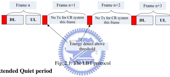
2.1, it shows the LBT concept that the CR system should listen to the channel before transmission. And if the energy detect is below the threshold, CR system will regard it as a white space and use this unlicensed band. If the energy detect is above the threshold, CR system will assume that there are WLAN users using the band now. We will consider the DL and UL subframes to be viewed as a single “packet” of constant duration equal to the frame duration. The BS shall allocate the UL subframe such that a time period is reserved between the end of UL allocations and the start of the frame preamble for the next DL subframe.
.
Fig. 2.1: The LBT protocol
Extended Quiet period
Extended quiet period (EQP) is a period of an integer number of frames when DL and UL transmission for CR users is suspended. By using EQP, the WLAN users will have enough time to finish their transmission. The EQP is shown in Fig 2.2.
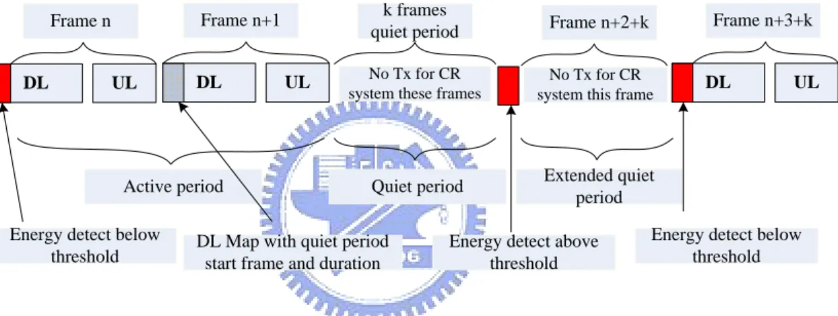
To detect white space, we combine LBT and EQP together as shown in Fig. 2.3. The CR BS will listen to the channel all the time and apply LBT to decide whether to occupy the channel or not. Once the CR system occupies the channel, CR BS will decide the active period and quiet period. We now assume the summation of active period and quiet period be one basic unit frame (BUF).
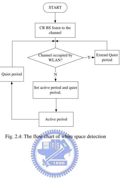
In summary, two mechanisms in 802.16h are adopted to do the white space detection in this thesis. To know more specifically, we construct the flow chart of white space detection in Fig. 2.4.
DL UL
Frame n k frames
quiet period
DL UL
Frame n+3+k
Energy detect above threshold
DL UL
Frame n+1 Frame n+2+k
No Tx for CR system this frame
Active period Quiet period Extended quiet period DL Map with quiet period
start frame and duration Energy detect below
threshold
Energy detect below threshold
No Tx for CR system these frames
START
CR BS listen to the channel
Set active period and quiet period. Channel occupied by WLAN? Active period Quiet period Extend Quiet period N Y
Chapter 3
System Model
To make clear of the system environment, we first introduce the CR network. As we know, CR network is composed of primary users and secondary users. Primary user stands for the user that is in the primary network which is the network that has exclusive right to use some specific spectrum. Primary network usually is composed of primary user and its base station. Secondary users (CR users) means the ones do not have license or permission to operate in its desired band. In order to access its desired band, they have to use DSA in order not to interfere the primary users. So we have to limit CR network’s interference to the primary users. CR network is composed of CR users and CR base station.
As shown in Fig. 3.1, 802.11 WLAN network is the primary network in 2.4 GHz unlicensed band. But in 2.0 GHz licensed band, to ease the traffic in WiMAX system, we will assign WiMAX non-real-time users to become CR users and change their behaviors to access the 2.4 GHz frequency band by adopting 802.16h mechanisms. That is, WiMAX users changed to CR users will access WLAN users’ spectrum by using DSA. The purpose is to improve the performance by efficiently using the white space in 2.4 GHz unlicensed band. In this topology, CR BSs are planned in a WiMAX cell, WLAN BSs are planned in the hotspot zone. The CR system will always operate
in 2.4 GHz unlicensed band. If there are both WLAN and CR systems operating in 2.4 Ghz, CR system will coexist with WLAN system, which is the main object we will discuss in this thesis. We assume the CR BSs are collocated with WLAN BSs in the hotspot zone.
Fig. 3.1: Topology of 802.16h networks with WiMAX and WLAN
In general, the interference between cells should be taken into account. However, with the cell planning, the interference from other cells could be reduced.
3.1 WiMAX System
IEEE 802.16 WiMAX-OFDMA system is designed for long-range, outdoor wireless broadband access, with high throughput. It can operate in 2~11 GHz frequency band. In this thesis, we assume that the WiMAX-OFDMA system operates in 2.0 GHz licensed band. In the licensed band, only some communication systems which have specific authorities can use this band. The maximum data rate that WiMAX-OFDMA can support is 30 Mbps when bandwidth is 10 Mhz. With variable channel bandwidth, its maximum data rate will be different. According to the channel
quality, different modulation orders are chosen such as QPSK, 16/64-QAM. We only consider the downlink transmission, with time-division multiplexing (TDM) is used as the protocol [12].
In the 802.16 WiMAX standard, it provides four service classes [13]: UGS (Unsolicited Grant Service), rtPS (real-time Polling Service), nrtPS (non-real-time Polling Service), BE (Best Effort). The UGS supports constant bit rate or throughput, such as E1/T1 lines and voice over IP (VoIP). The rtPS is designed to support real-time data streams with guaranteeing on throughput and latency, such as MPEG video. The nrtPS only guarantees throughput and is designed to support delay-tolerant streams, such as Hypertext Transport Protocol (HTTP) service. The BE provides no guarantees on throughput or delay, such as File Transfer Protocol (FTP). Generally speaking, UGS, rtPS, nrtPS guarantee QoS , but BE doesn’t support QoS.
3.2 WLAN System
IEEE 802.11 WLAN system operates in 2.4 GHz unlicensed band (ISM band). In the unlicensed band, every communication system can access this frequency band under the FCC transmitter power constraints. 802.11 use direct sequence spread spectrum (DSSS) with 22 MHz bandwidth per channel. The total spectrum used for 802.11 is about 72 MHz. Three non-overlapping channels are considered in this thesis (channel 1, 6, and 11) as the center frequency for coexistence of WLAN and CR systems. In the WLAN cell, mobile node’s information are collected and recorded by the WLAN access point. In order to provide transmission and authorization, we assume all access points are connected by a wired core network. There are two ways to do media access control (MAC) in WLAN networks: distributed coordinator function (DCF) and point coordinator function (PCF). In DCF, it uses slotted binary
exponential backoff scheme based on the carrier sense multiple access with collision avoidance (CSMA/CA) protocol. In PCF, it uses centralized control by the WLAN access point. In this thesis, we consider DCF for MAC which is based on CSMA/CA.
Because 802.11b system uses High-Rate DSSS, so it must use one of the 3 CCA (Clear Channel Assessment) modes: CCA Mode 1、CCA Mode 4、CCA Mode 5 [14]. In the first mode (CCA Mode 1), when “any signal” is detected above the energy detection (ED) threshold in the channel, it will report “busy”. On the contrary, it will report “not busy” when energy drops below the ED threshold. In the second mode (CCA Mode 4), upon the High Rate DSSS signal is detected, the device declares the channel “busy” and starts a 3.65 ms timer. When the timer expires, and no High Rate DSSS is detected, the channel will declared “idle” or “not busy”. The third mode (CCA Mode 5) is the combining of CCA Mode 1 and CCA Mode 4.Itonly declares the channel “busy” if a specifically formed High Rate DSSS signal is detected, but declares the channel is not busy when energy drops below the ED threshold. In this thesis, we only consider the CCA Mode1.
In the conclusion, we consider DCF for MAC which is based on the CSMA/CA protocol and CCA Mode 1 for the WLAN system.
3.3 CR System
We assume the CR network systems are 802.16 WiMAX-OFDMA systems. In this thesis, we assume the WiMAX BS will assign the non-real-time WiMAX users to become the CR users and they will start to access the 2.4 GHz unlicensed band originally occupied by WLAN systems. Then we have to do the DSA mechanism for the CR users in 2.4 GHz.
In this thesis, CR BS is collocated with the WLAN access point in the hot spot zone. Fig. 3.2 illustrates the infrastructure of CR system. We assume that all CR BSs work as the transceivers and are connected with the wired core network by the wired lines. WiMAX BS here will do the original operation in 2.0 GHz licensed band and the data scheduling for the CR BSs in 2.4GHz unlicensed band by the access service network (ASN) network. That is, when the WiMAX users become the CR users, WiMAX BS will do the scheduling and immediately transmits the data to the CR BSs which work as transceivers. CR BSs will do the white space detection in 2.4GHz and deicide both active period and quiet period. We also assume the CR BSs have perfect channel state information (CSI) and only downlink transmission problems are considered here. WiMAX BS ASN CR BS Wired lines CR user CR BS CR user CR BS CR user ASN-GW
Chapter 4
Active Period Adaptation by Fuzzy
Logic Theory
To earn the better efficiency for coexistence of WLAN and CR systems, we propose CR-based DSA algorithm to adapt the active period (AP) for CR system. The CR-based DSA algorithm, shown in Fig. 4.1, contains two parts: white space detection and fuzzy active period adaptor (FAPA). White space detection has been discussed in chapter 2 by adopting the LBT and EQP techniques. After doing white space detection, to seek the balance between raising the usage of the white space and decreasing the interference to the WLAN users, we will use fuzzy theory to design the duration of active period (AP) in a constant basic unit frame (BUF). Then CR system will have white space for downlink transmission.
Fig. 4.1: CR-based dynamic spectrum access algorithm
The busy ratio of WLAN network is considered as an important parameter for the adjustment of white space usage. The busy ratio of WLAN network, denoted by ρ, is defined as
the time occupied by WLAN system in quiet period and extended quiet period =
quiet period + extended quiet period
ρ (4.1)
That is, the CR BS will listen to the channel and calculate ρ.
We also consider the length of EQP as an important parameter for observation on the traffic condition in WLAN network. We assume now we will use the k’th BUF, which denoted by BUF k . That is, if the length of EQP observed at ( ) BUF k( − is 1) small, we can presume that the traffic in WLAN is low in this time period. On the contrary, if the length of EQP observed at BUF k( − is large, we will presume that 1) the traffic in WLAN network is rising in this time period. To be objective, we take weighted average number of consecutive three EQP observed before BUF k( − , 1) that is
( 1) ( 1) ( 2) ( 3)
We consider EQP k( − will have more information for predicting the traffic of 1) WLAN than EQP k( − , So we set 2) α β> . In the same reason, we can get
> >
α β γ , and we set α =0.5, β =0.33, γ =0.17 here.
Besides, the length of AP in the BUF majorly affects the throughput and packet delay for both WLAN and CR system. So we will adjust active period at the next time when we use the white space depending on the busy ratio, the active period, and weighted average EQP in this BUF. Assume BUF is a constant and is set to be 100 frames here. To get the better utilization, we apply the fuzzy logic approach and choose the inputs given below:
z ρ(k− : busy ratio of WLAN measured at 1) BUF k( − , input value:[0~1]. 1)
z N k( − : frames of active period in 1) BUF k( − , input value: [0 frames~95 1) frames).
z EQP k( − : weighted average number of EQP before starting using 1) BUF k , ( )
input value:[0 frames~∞ frames).
We construct FAPA system, shown in Fig. 4.2. Through the FAPA system, we can get an output:
z ΔN k( ) : variation in N at BUF k , for its range [( ) − 100%~100%]. That is,
( ) ( 1) (1 ( ))
N k =N k− ⋅ + ΔN k .
Because the BUF is set to be 100 frames and we set to release at least 5 frames to be the quiet period in order to measure the WLAN’s busy ratio, therefore N k can ( ) be obtained by
( ) min( 95, ( 1) (1 ( )) 0.5 )
N k = ⎢⎣N k− × + ΔN k + ⎥⎦ , (4.3)
where ⎢⎣N k( − × + Δ1) (1 N k( )) 0.5+ ⎥⎦ means to round off the whole number of
( 1) (1 ( )) N k− ⋅ + ΔN k . FAPA Input Output ( −1) EQP k ( −1)
ρ
k ( −1) N k ΔN k( )Fig. 4.2: Inputs and output of fuzzy AP adaptor
Next we define the term sets of inputs and output of the fuzzy AP adaptor. For term sets of input variables N k( − , (1) ρ k− , and 1) EQP k( − , ( (1) T N k−1)) = {Small (S), Middle (M), Large (L)}, ( (T ρ k−1)) = {Low (L), Medium (M), High (H)}, and T EQP k( ( −1)) = {Calm(C), Rising (R), More Rising (MR)}, respectively. For term set of output variable ΔN k( ), (T ΔN k( ))= {Severely Decrease (SD), Decrease (D), Lightly Decrease (LD), Maintain (M), Lightly Increase (LI), Increase (I), Severely Increase (SI) }.
4.1 Membership Function and Fuzzy Rule Base
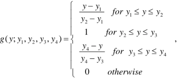
1 1 2 2 1 2 3 1 2 3 4 4 3 4 4 3 1 ( ; , , , ) 0 − ⎧ ≤ ≤ ⎪ − ⎪ ≤ ≤ ⎪ = ⎨ − ⎪ ≤ ≤ ⎪ − ⎪ ⎩ y y for y y y y y for y y y g y y y y y y y for y y y y y otherwise , (4.4)
where parameters y1 and y4 represent two terminals of lower parallel side, and 2
y and y3 represent two terminals of upper parallel side.
Also denote the triangular function by f(.) which is expressed as
1 1 2 2 1 3 1 2 3 2 3 3 2 ( ; , , ) 0 − ⎧ ≤ ≤ ⎪ − ⎪ − ⎪ =⎨ − ≤ ≤ ⎪ ⎪ ⎪ ⎩ y y for y y y y y y y f y y y y for y y y y y otherwise , (4.5)
where y (or 1 y , 2 y ) in 3 f( )⋅ is the left edge (or center, right edge) of the triangular function. The function g( )⋅ and ( )f ⋅ are shown as Fig. 4.3.
1 y f(y) 1 y y2 y3 1 y g(y) 1 y y2 y3 y4 (a) (b)
Fig. 4.3: Definitions for (a) function g( )⋅ and (b) function f( )⋅
In WLAN system, we mainly focus on the HTTP non-real-time (NRT) users, so we will specifically discuss about the NRT HTTP users in the following contents. In [15], we can know the delay requirement for NRT users in WLAN is 1000ms. From
this saying, we will purchase best utility of AP in the limit of delay requirement in 1000ms for WLAN users. In other words, CR systems have to try their best to ease the effect on WLAN and let delay of HTTP users in WLAN can limit below 1000ms.
We assume the membership function is ( )μ ⋅ . For the input ρ, we denote
( ( 1))
L k
μ ρ − , ( (μ ρM k−1)), and μ ρH( (k−1)) the membership functions for the linguistic terms “L”, “M”, and “H”, respectively. They are given below and shown in Fig. 4.4(a):
μ ρL( (k−1)) = ( (g ρ k−1); 0, 0, 0.2, 0.3), (4.6)
μ ρM( (k−1)) ( (= g ρ k−1); 0.2, 0.3, 0.55, 0.7), (4.7)
μ ρH( (k−1)) ( (= g ρ k−1); 0.55, 0.7, 1, 1). (4.8)
The reason we choose those parameter in μ ρ( ) is according to the simulation result of WLAN collision probability and WLAN average packet delay in Fig. 4.5 and Fig. 4.6. We define the offered WLAN traffic intensity as the ratio of the total average arrival rate of all WLAN users over the system maximum transmission rate which is 11 Mbps in 802.11b. Fig. 4.6(a) shows the average WLAN packet delay with traffic intensity varies from 0.1 to 0.55 where Fig. 4.6(b) is with traffic intensity varies from 0.1 to 0.6. In Fig 4.5, that there is an apparent change at the traffic intensity around 0.55. We can regard it as the WLAN traffic is getting high and the collision probability is increasing rapidly. When the offered traffic intensity is greater than 0.7, the slope of collision probability will decrease and we can regard the WLAN traffic is very high now and almost saturated. So we will set 0.55 and 0.7 as the values for left edge of trapezoid representing the term “High (H)”. In Fig. 4.5 and Fig. 4.6(a), when the traffic intensity of WLAN is smaller than 0.3, the average delay and collision
probability of WLAN users is very small and not much change, so we will take traffic intensity equals 0.2 and 0.3 into our consideration for the right edge of trapezoid representing the term “Low (L)” and the range for representing the term “Medium (M)” is bound by 0.2, 0.3, 0.55, and 0.7. So we arrange these numbers and set them to be the bound of the Low, Medium, High area.
Besides, in Fig. 4.6(a) and Fig. 4.6(b), the average delay of WLAN users will be below the delay requirement of 1000 ms and it will much higher than 1000 ms when the traffic intensity is greater than 0.6. So we can rewrite the constrain mentioned above, that is, CR systems have to try their best to ease the effect on WLAN and let delay of HTTP users in WLAN can limit below 1000ms at the traffic intensity equals 0.55.
The membership functions for the input N k( − for the terms “S”, “M”, and 1) “L”, denoted by μS( (N k−1)), μM( (N k−1)), and ( (μL N k−1)) can be expressed by and shown in Fig. 4.4(b):
( ( 1)) ( ( 1); 0, 0, 25, 35)
S N k g N k
μ − = − , (4.9)
μM( (N k−1)) = ( (g N k−1); 25, 35, 45, 55), (4.10)
μL( (N k−1)) ( (= g N k−1); 45, 55, 100, 100). (4.11)
The reason we choose those parameters for μS( (N k−1)) is that we know the delay in WLAN system will fiercely increase when the traffic intensity is about 0.5 ~ 0.6 because of the binary exponential backoff scheme. It can be seen from Fig. 4.6(a), when traffic intensity is about 0.55, the average packet delay of WLAN users is below 1000 ms, closing to the delay requirement. When the traffic intensity is higher, the delay of WLAN users will be over 1000ms. This, it can be estimated that, in the
situation of traffic intensity in WLAN networks is lower than 0.55, CR BS can use about 25 to 35 frames for active period in one BUF and the delay of WLAN users will not increase obviously. Further more, the reason we choose the parameter in μM( )N
and ( )μL N is that there will be obviously degradation in the performance of WLAN
networks when CR users use about 45 or 55 frames in one BUF. Because of these apparent changes that can be observed from Figs. 4.6(a) and 4.6(b), we choose those parameters in μS( )N , ( )μM N and μL( )N .
The membership functions for the EQP k( − for the terms “C”, “R”, and “MR”, 1)
denoted by μC(EQP k( −1)), (μR EQP k( −1)), and μMR(EQP k( −1)) can be expressed by and shown in Fig. 4.4(c):
11 17 ( ( 1)) ( ( 1); 0, 0, , ) 6 6 C EQP k g EQP k μ − = − , (4.12) ( ( 1)) ( ( 1); , , )11 28 56 6 6 6 R EQP k f EQP k μ − = − , (4.13) ( ( 1)) ( ( 1); 35, 56, , ) 6 6 MR EQP k g EQP k μ − = − ∞ ∞ . (4.14)
The following will explain the reason we choose theses values in μ(EQP k( −1)). First, we will set the threshold values λ1, λ2 for WLAN users. If ρ( )<k λ ρ1⋅ (k− , 1) we will regard the traffic is steady. If λ ρ1⋅ (k− ≤1) ρ( )k ≤λ ρ2⋅ (k− , we will 1) regard the traffic is getting high and congested. If λ ρ2⋅ (k−1)< ( )ρ k , we will regard the traffic is very intense. We separate them into three cases,
(i) When ρ( )<k λ ρ1⋅ (k− , put 1) EQP k( − into group 1) φ1.
(iii) When λ ρ2⋅ (k−1)< ( )ρ k , put EQP k( − into group 1) φ3.
1
λ and λ2 are respectively set to be 2 and 3 here. We regard the values of ( 1)
EQP k− in groups φ1 , φ2, φ3 as a very important index to set our parameters
in μC(EQP k( −1)), μR(EQP k( −1)), μMR(EQP k( −1)). After gathering statistics
and calculating, we obtain those parameters in μ(EQP k( −1)).
For the output ΔN, we uniformly separate the number between -100 % to 100%. So the membership function will be the follows shown in Fig. 4.4(d):
μSD(+N k( )) (= g +N k( ); 100, 100, 70, 60)− − − − , (4.15) μD(+N k( )) (= g +N k( ); 70, 60, 40, 30)− − − − , (4.16) ( ( )) ( ( ); 40, 30, 10, 5) LD N k g N k μ + = + − − − − , (4.17) ( ( )) ( ( ); 10, 5, 5, 10) M N k g N k μ + = + − − , (4.18) ( ( )) ( ( ); 5, 10, 30, 40) LI N k g N k μ + = + . (4.19) ( ( )) ( ( ); 30, 40, 60, 70) I N k g N k μ + = + , (4.20) ( ( )) ( ( ); 60, 70, 100, 100) SI N k g N k μ + = + . (4.21)
From above, we can have the diagram for the membership functions as shown in Fig. 4.4.
( ) μ ρ ρ (a) ( ) μ N N (b) EQP ( ) μ EQP 11 6 17 6 28 6 35 6 56 6 (c) ( ) μ ΔN ΔN (d)
0 0.1 0.2 0.3 0.4 0.5 0.6 0.7 0.8 0.9 1 0 0.1 0.2 0.3 0.4 0.5 0.6 0.7 0.8 0.9 1
Offered WLAN Traffic Intensity
C o llis io n P robabi li ty Pure-WLAN
Fig. 4.5: Collision probability in WLAN system
0.1 0.15 0.2 0.25 0.3 0.35 0.4 0.45 0.5 0.55 0.6 0 50 100 150 200 250 300 350 400 450
Offered WLAN Traffic Intensity
A v er ag e WLA N P a c k et D el ay ( m s ) Pure-WLAN (a)
0 0.1 0.2 0.3 0.4 0.5 0.6 0.7 0 0.5 1 1.5 2 2.5 3x 10 5
Offered WLAN Traffic Intensity
A v er ag e WLA N P a c k et D el ay ( m s ) Pure-WLAN (b)
Fig. 4.6: Average WLAN packet delay
After setting up the membership functions of inputs and output, we will build 27 fuzzy rules as the fuzzy rule base in Table 4.1 to do the defuzzification:
Table 4.1: The rule base of fuzzy AP adaptor
Rule ρ N EQP ΔN 1 L S C SI 2 L S R I 3 L S MR LI 4 L M C I 5 L M R LI 6 L M MR M 7 L L C LI 8 L L R M 9 L L MR LD 10 M S C I 11 M S R LI 12 M S MR M 13 M M C LI
From the fuzzy rule base, we can know the strategies we should take according the inputs numbers. Next we will do the defuzzification procedure.
4.2
Defuzzification
We adopt the max-min inferred method and use the center of gravity (COG) method for defuzzification method [16]. To briefly explain max-min inference method, we assume now we only have two fuzzy rules for two inputs, one output fuzzy logic theory problem. For term sets of input variables x and y , T x = ( )
{A A }, ( )1, 2 T y = {B B }, respectively. For term set of output variable 1, 2 z , ( )T z =
{C C }. There are two fuzzy rules, 1, 2
Rule 1: If inputs x is A and y is 1 B , then z is 1 C , (4.22) 1
Rule 2: If inputs x is A and y is 2 B , then z is 2 C . 2 (4.23) Now the input values for x and y are x and 0 y , so we will apply the “min” 0
14 M M R M 15 M M MR LD 16 M L C LI 17 M L R M 18 M L MR LD 19 H S C LI 20 H S R M 21 H S MR LD 22 H M C LD 23 H M R D 24 H M MR D 25 H L C LD 26 H L R D 27 H L MR SD
operator to obtain the min membership function values for fuzzy rule 1 and rule 2, 1 1 1=min{μA( 0), (μB 0)} m x y , (4.24) 2 2 2 =min{μA ( 0), (μB 0)} m x y . (4.25)
Subsequently, applying the “max” operator through the COG method, a crisp value is exported to decide which action will be applied. To be more specifically, we assume the COG of membership function
1( )
μC z and
2( )
μC z respectively locates
at z=z and 1 z=z . Then the crisp output value 2 z is obtained as follows: o
1 1 2 2 0 1 2 ⋅ + ⋅ = + z m z m z m m (4.26)
Fig. 4.7 is the total procedure of max-min method for defuzzification in this example. ( ) μ x ( ) μ x ( ) μ y ( ) μ y x x y y 0 = x x y= y0 1 A 2 A 1 B 2 B ( ) μ z ( ) μ z 1 C 2 C z z ( ) μ z z 1 m 2 m
Chapter 5
Simulation Results and Discussion
In the simulation, we consider DCF for MAC which is based on CSMA/CA for WLAN system. Referred to specifications of IEEE 802.11 [14], we set the values of PHY-related parameters for WLAN system in Table 5.1.
Table 5.1: Simulation Parameters for WLAN system
Parameters Values Slot time 20 sμ DIFS 20 sμ SIFS 10 sμ Propagation Delay 1 sμ Bit rate 11 Mbps PHY overhead 192 sμ
MAC header 28 byte
ACK length 14 byte
Data packet Payload 1500 byte
Initial Contention Window 32
Maximum Contention Window 1024
For CR system, we only consider downlink transmissions and the system parameters are compatible with IEEE 802.16 standard [17]. Table 5.2 lists the system
parameters of the considered CR system. In this thesis, we assume the CR system adopts 20 MHz spectrum when operating in unlicensed spectrum and the frame duration is 5 ms. The number of subcarriers is equal to the FFT size, 2048, but only 1536 subcarriers are used for data transmission, while the others are used for pilot channel or guard channel. Modulation order is fixed at QPSK for CR systems in unlicensed spectrum.
Table 5.2: Simulation Parameters for CR system
Parameters Values
System bandwidth 20 MHz
FFT size 2048
CR frame duration 5 ms
CR symbol duration 102.86 sμ
Number of data subcarriers 1536
Number of subchannels 32
Number of data subcarriers per subchannel
48
Number of CR symbol for downlink transmission per CR frame
25
Modulation order QPSK
5.1 Scenario
Fig. 5.1 shows the simulation scenario in this thesis. We simulate single cell case where one WLAN access point and the CR BS is collocated with same coverage in unlicensed band. The CR user appears in the WLAN cell (the gray zone) shown in Fig. 5.1 and the CR user can access 2.4 GHz unlicensed band by using DSA. We evaluate the performance of CR users in the single cell to investigate the advantage of the proposed FAPA mechanism.
Fig. 5.1: Simulation Scenario
5.2 Source Traffic Model of WLAN System
As mentioned before, we mainly focus on the HTTP non-real-time (NRT) users. So each WLAN user’s traffic model is modeled as HTTP NRT traffic, where the traffic of HTTP user is modeled as a sequence of page downloads. Each page is composed of a main object and several embedded objects, each object is divided into several packets. The session can be regarded as ON/OFF periods in order to represent web-page downloads and the intermediate reading times. These ON and OFF periods are a result of human interaction where the page download represents a user’s request for information and the reading time identifies the time required to digest the web-page. Reading time is distributed in an exponential distribution. The parameters for HTTP traffic model are defined in Table 5.3 [18].
Table 5.3: Simulation Parameters for WLAN system
Component Distribution Parameters
Main object size Truncated Lognormal Mean = 10710 bytes, Std. dev. = 25032 bytes,
Max = 2 Mbytes, Min = 100 bytes Embedded object size Truncated Lognormal Mean = 7758 bytes,
Std. dev. = 126168 bytes Max = 2 Mbytes,
Min = 50 bytes Number of embedded
objects per page
Truncated Pareto Mean = 5.64, Max = 53
Inter-arrival time between each page
Exponential Mean = 3 sec
Packet size Deterministic Chop from objects
with size 1500 bytes Packet inter-arrival time Exponential Mean = 0.013 second
5.3 Performance Evaluation
In the simulation, the number of WLAN users is increased from 8 to 69. We define the offered WLAN traffic intensity as the ratio of the total average arrival rate of all WLAN users over the system maximum transmission rate which is 11 Mbps in 802.11b. In our simulation, all WLAN users are assumed to have identical traffic arrivals with same average arrival rate to be 145 kbps. Thus, the offered WLAN traffic intensity varies from 0.1 to 0.9 as the number of WLAN users varies from 8 to 69.
In the performance evaluation, we compare the systems consisting of WLAN and CR systems with FAPA to the CR systems with fixed active period in the specific range of busy ratio to proposed in [9]. To the fixed active period mentioned above, the active period values are chosen as follow:
Active period values: 70 frames, 0 33% 50 frames, 33% 66% 10 frames, 66% 100% ρ ρ ρ ≤ < ⎧ ⎪ ≤ < ⎨ ⎪ ≤ ≤ ⎩ (5.1)
As mentioned before, the basic unit frame (BUF) of each duty cycle values is 100 frames.
Fig. 5.2 shows the proportion of idle time in unlicensed spectrum, which means the total idle time in unlicensed spectrum over the total simulation time. Legend “FAPA” stands for the CR system using FAPA in this thesis, “Fixed-AP” stands for the CR system using specific AP mentioned in (5.1) and “Pure-WLAN” stands for the WLAN system without CR system,
Fig.5.2 shows that the CR system with Fixed-AP and FAPA indeed have smaller idle time ratio in unlicensed spectrum at low and middle offered WLAN traffic intensity. Furthermore, FAPA decrease more idle time ratio than Fixed-AP method. The phenomenon is expected since FAPA can adapt the AP according the situation of the WLAN traffic. Thus it can use unlicensed spectrum more efficiently than Fixed-AP. Besides, we can see when the offered WLAN traffic intensity is high, about 0.6~0.9, the proportion of idle time of WLAN system without CR system is very small. That means it is hard for CR system to access the unlicensed spectrum because the contentions between WLAN users are fierce and there is nearly no white space for CR system. In this situation, CR system should decrease AP in unlicensed spectrum in order not to interfere WLAN system.
Fig. 5.3 shows the CR system throughput gained by CR-based DSA in unlicensed spectrum. It can be found that CR system obtain large throughput in unlicensed spectrum when the offered WLAN traffic intensity is light. Furthermore, we can see FAPA is higher than the Fixed-AP. That means through FAPA, we can use more
white space by adaptively increase AP than Fixed-AP method. When the offered WLAN traffic intensity is smaller than 0.3, compared to Fixed-AP, there is about 15~20 % throughput improved by using FAPA. In the middle offered WLAN traffic intensity around 0.4 to 0.55, FAPA is a little bit better than Fixed-AP method and the
0 0.1 0.2 0.3 0.4 0.5 0.6 0.7 0.8 0.9 1 0 0.1 0.2 0.3 0.4 0.5 0.6 0.7 0.8 0.9 1
Offered WLAN Traffic Intensity
T he P ro po rt ion of I dl e T im e FAPA Fixed-AP Pure-WLAN
Fig. 5.2: The proportion of idle time in unlicensed spectrum
both throughputs are getting smaller. The reason is that when the WLAN traffic intensity is increasing, the idle period in unlicensed spectrum is decreasing. There is no much white space for CR system to access, so both FAPA and Fixed-AP method will gain smaller throughput. In the high offered WLAN traffic intensity, which is beyond 0.6, it can found that the throughput of Fixed-AP method is small. The reason is that for the high WLAN traffic intensity, CR system will frequently observe very high busy ratio ρ , by (5.1), it will regularly use 10 frames for AP. For FAPA in high offered WLAN traffic intensity, CR system can observe that the traffic is high now,
and through Fig. 5.2 we can know there is a very few idle time for CR system to use. From the reasons above, CR system with FAPA will decrease AP in order not to affect WLAN system.
0 0.1 0.2 0.3 0.4 0.5 0.6 0.7 0.8 0.9 1 0 1 2 3 4 5 6 7 8 9 10 11
Offered WLAN Traffic Intensity
T h e In di v idua l C R s y s tem T h rou gh pu t (M bp s ) FAPA Fixed-AP
Fig. 5.3: The individual CR system throughput
Fig. 5.4 shows the throughput of WLAN systems. In WLAN systems without CR, the throughput will increase with offered WLAN traffic intensity when the traffic intensity is smaller than 0.55. This phenomenon is expected since current channel resource is larger than current users’ needs. When the traffic intensity is high and is greater than 0.6, the throughput of WLAN systems will decrease with offered WLAN traffic intensity. That is because there are too many WLAN users in WLAN system and cause more contention. So collision probability in WLAN system will increase and decrease the successful transmission probability in WLAN system. Besides, the throughput of the WLAN system with CR is also shown in Fig. 5.4. For FAPA, the
throughput of WLAN system is much the same with WLAN system without CR. This means FAPA can adjust its usage in 2.4 GHz spectrum efficiently on the premise that reduces the interference in WLAN system.
0 0.1 0.2 0.3 0.4 0.5 0.6 0.7 0.8 0.9 1 0 1 2 3 4 5 6
Offered WLAN Traffic Intensity
W L A N S y s te m T h ro ug hp ut ( M b p s ) FAPA Fixed-AP Pure-WLAN
Fig. 5.4: The throughput of WLAN system
For Fixed-AP, the throughput of WLAN system is close to the WLAN system without CR before the traffic intensity is smaller than 0.5. But when the traffic intensity is greater than 0.55, the throughput of WLAN system will decrease and lower than the WLAN system without CR. This can be explained that CR system with Fixed-AP can’t timely adjust its usage in 2.4 GHz spectrum and it causes interference in WLAN system.
With phenomena shown in Fig. 5.3 and Fig. 5.4, we can see although the throughput of Fixed-AP is larger than the CR system with FAPA when the offered
WLAN traffic intensity is greater than 0.6. But Fixed-AP method indeed interferes with WLAN system and cause the throughput of WLAN system decreased. So FAPA decreases its throughput of CR system in order not to interfere with WLAN system in a reasonable way and cause the lower throughput than Fixed-AP method.
Fig. 5.5 depicts the average packet delay of WLAN system. We can find that the average packet delay of WLAN systems operates with CR system will be larger than WLAN system without CR. The reason is that when CR system occupies the channel, WLAN users have to wait until CR users finish transmitting in AP. So the average packet delay of WLAN system will increase when we assign CR system to coexist with WLAN system. When the offered WLAN traffic intensity is smaller than 0.3, the average WLAN packet delay of WLAN system operates with CR system will be very close and is steady. That means the CR system can adjust its AP in order not to affect the WLAN packet delay. When the offered WLAN traffic intensity is greater than 0.4,
the average delay will increase because the unlicensed spectrum is getting busy. We can find that, for the WLAN system operates with the CR system, the packet
delay for WLAN system is below 1000 ms when using FAPA at offered WLAN traffic intensity equals 0.55. That means we satisfy the constraint we set, that is, the CR systems have to try their best to ease the effect on WLAN and let delay of HTTP users in WLAN can limit below 1000 ms. On the other hand, we can find for Fixed-AP method, the delay is much bigger than 1000 ms (about 22000 ms) when offered WLAN traffic intensity equals 0.55. That means FAPA can indeed use white space more efficiently and cause less interference than Fixed-AP method in the reasonable delay requirement. For the offered WLAN traffic intensity is greater than 0.6, the WLAN packet delay is very large due to the fierce collision, so we won’t consider their delay performance here.
0 0.1 0.2 0.3 0.4 0.5 0.6 0 100 200 300 400 500 600 700 800 900 1000
Offered WLAN Traffic Intensity
A v er ag e W LA N P ac k e t D el a y ( m s ) FAPA Fixed-AP Pure-WLAN
Chapter 6
Conclusions
With the increasing demand for additional bandwidth due to the existing and new services, the available spectrums are most limited and used by the specific licensed holders. But the spectrum usage is inefficiently and we have to seek a new communication paradigm to access the white space in existing wireless spectrum to solve the spectrum scarcity. Two mechanisms proposed in IEEE 802.16h called Listen-Before-Talk (LBT) and Extended Quiet Period (EQP) are adopted to do the white space detection in this thesis. After doing white space detection, a CR-based dynamic spectrum access (DSA) algorithm with fuzzy active period adaptor (FAPA) is proposed for CR systems downlink transmission. The utilization of the white space is controlled by FAPA algorithm. The goals of FAPA for CR-based DSA are to optimize the utilization of the CR system in a fixed bandwidth without interfere the primary users.
In the simulation results and discussion, the CR-based DSA algorithm with FAPA is compared to CR-based DSA algorithm with Fixed-AP method. From the results, we can conclude that in the overall throughput, FAPA performs better than Fixed-AP method we compared in the reasonable way. That means through intelligent technology of fuzzy logic, we can adjust AP instantaneously and effectively according
the variation of situation it observed. FAPA algorithm also reduces more idle time in unlicensed spectrum than Fixed-AP method. It shows that FAPA can fully utilize the unlicensed spectrum. Furthermore, in the performance of WLAN packet delay, FAPA algorithm can satisfy the 1000 ms delay requirement at traffic where Fixed-AP method is far beyond it.
Because of the real-time computation ability of fuzzy logic system, we can see that FAPA can timely adjust the usage of white space for this non-linear control problem. Through its ability of adjustment, we can gain more throughput for CR system with slightly interfering the WLAN system in 2.4 GHz unlicensed band.
Bibliography
[1] Federal Communications Commission, “Notice of proposed rule making and order,” ET Docket No 03-222, Dec. 2003.
[2] S. Haykin, “Cognitive radio: brain-empowered wireless communications,” IEEE Selected Areas in Communications, Vol. 23, Issue 2, pp. 201-220, Feb. 2005.
[3] P. Sutton, L.E. Doyle, and K.E. Nolan, “A reconfigurable platform for cognitive networks.” International Conference on Cognitive Radio Oriented Wireless Networks and Communications, pp. 1-5, Jun. 2006.
[4] N. Devroye, P. Mitran and V. Tarokh, “Cognitive decomposition of wireless networks,” International Conference on Cognitive Radio Oriented Wireless Networks and Communications, pp. 1-5, Jun. 2006.
[5] S. Srinivasa, S.A. Jafar, “Cognitive radios for dynamic spectrum access - the throughput potential of cognitive radio: a theoretical perspective,” IEEE Communications Magazine, Vol. 45, Issue 5, pp. 73–79, May 2007.
[6] S. Mangold, K. Challapali, “Coexistence of wireless networks in unlicensed frequency bands,” Wireless World Research Forum #9, Zurich Switzerland, Jul.
2003.
[7] X. Jing, D. Raychaudhuri, “Spectrum co-existence of IEEE 802.11b and 802.16a networks using CSCC etiquette protocol,” IEEE DySpAN’2005, pp. 243–250, Nov.
2005.
[8] IEEE Standard Std. 802.16h: Improved coexistence mechanisms for license-exempt operation.
[9] C. H. Liu, “Dynamic spectrum Access and white space detection for cognitive radio networks,” Master Thesis, Department of Communication Engineering,
National Chiao Tung University, June 2007.
[10] C. T. Lin, C. S. G. Lee, “Neural Fuzzy Systems,” Prentice-Hall, 1996.
[11] I.F. Akyildiz, W.Y. Lee, M.C. Vuran, S. Mohanty, “Next generation/dynamic spectrum access/cognitive radio wireless networks: A survey,” Comput. Networks,
pp. 2127–2159, Sep. 2006.
[12] X. Jing, S. Mau, D. Raychaudhuri, R. Matyas, “Reactive cognitive radio algorithms for co-existence between IEEE 802.11b and 802.16a networks,” IEEE Global Telecommunications Conference, 2005. (GLOBECOM '05) , Vol. 5, pp.
5-9, 28 Nov.-2 Dec. 2005.
[13] Q. Liu, X. Wang, G.B. Giannakis, “A cross-layer scheduling algorithm with QoS support in wireless networks,” IEEE Transactions on Vehicular Technology, Vol.
55, No. 3, pp. 839-847, May 2006.
[14] IEEE Standard Std. 802.11b-1999: Wireless LAN medium access control (MAC) and physical layer (PHY) specifications.
[15] J. Jackson Juliet Roy, V. Vaidehi, S. Srikanth, “A QoS weight based multimedia uplink scheduler for IEEE 802.11e WLAN,” International Conference on Signal
Processing, Communications and Networking, 2007. ( ICSCN '07) , pp. 446-451,
Feb. 2007.
[16] H. J. Zimmermann, “Fuzzy set theory and its applications,” 4th edition, Kluwer Academic Publishers, 2001.
[17] IEEE 802.16m-08/oo4r1,”IEEE 802.16m Evaluation Methodology Document (EMD),” 2008-03-17.
[18] 3GPP, “Feasibility study for orthogonal frequency division multiplexing (OFDM) for UTRAN enhancement,” 3GPP TR 25.892 V6.0.0, June 2004.
Vita
Hao-Hsiang Sun was born on 1984 in Tainan, Taiwan. He received the B.E. and M.E. degree in department of communication engineering from National Chiao-Tung University, Hsinchu, Taiwan, in 2006 and 2008, respectively. His research interests include radio resource management and wireless communication systems.