http://pii.sagepub.com/
Control Engineering
Engineers, Part I: Journal of Systems and
http://pii.sagepub.com/content/219/4/259
The online version of this article can be found at:
DOI: 10.1243/095965105X9597
2005 219: 259
Proceedings of the Institution of Mechanical Engineers, Part I: Journal of Systems and Control Engineering
Kai-Tai Song and Chen-Chu Chlen
Visual tracking of a moving person for a home robot
Published by:
http://www.sagepublications.com
On behalf of:
Institution of Mechanical Engineers
can be found at:
Engineering
Proceedings of the Institution of Mechanical Engineers, Part I: Journal of Systems and Control
Additional services and information for
http://pii.sagepub.com/cgi/alerts Email Alerts: http://pii.sagepub.com/subscriptions Subscriptions: http://www.sagepub.com/journalsReprints.nav Reprints: http://www.sagepub.com/journalsPermissions.nav Permissions: http://pii.sagepub.com/content/219/4/259.refs.html Citations:
What is This?
- Jun 1, 2005
Version of Record
>>
Visual tracking of a moving person for a home robot
Kai-Tai Song* and Chen-Chu Chien
Department of Electrical and Control Engineering, National Chiao Tung University, Hsinchu, Republic of China The manuscript was received on 22 January 2004 and was accepted after revision for publication on 25 February 2005. DOI: 10.1243/095965105X9597
Abstract: This paper presents a visual tracking system for a home robot to pursue a person. The system works by detecting a human face and tracking a person via controlling a two-degree-of-freedom robot head and the robot body. An image processing system has been developed to extract facial features using a complementary metal-oxide semiconductor (CMOS) web camera. An algorithm is proposed to recognize a human face by using skin colour and elliptical edge information of a human face. A digital signal processing (DSP)-based motor control card is designed and implemented for robot motion control. The visual tracking control system has been integrated on a self-constructed prototype home robot. Experimental results show that the robot tracks a person in real-time.
Keywords: tracking control, human–robot interaction, intelligent robots, image processing
1 INTRODUCTION localization. The home robot R100 developed by NEC Corp. is equipped with two colour CCD cameras In recent years, many researchers have been interested for detecting, tracking, and recognizing humans. in developing home robots for providing various R100 can recognize about ten persons and records services and entertainment functions in a home observed objects. The robot Colin uses stereo vision setting. These new types of robot might become for detecting, tracking, and pursuing a human [3]. popular home appliances in the near future. The main Several approaches to robot visual tracking have difference between home robots and conventional been reported. In references [4] to [6], robotic visual household appliances is in the way that robots inter- tracking systems were designed to detect a human act with family members. Speech communication face using skin colour. In reference [7], shape infor-and vision recognition are important factors for mation and facial features (eyes, mouth, nose) are intelligent human–robot interaction. Charge coupled utilized. Using one cue for detecting a human face device (CCD) cameras have been the most utilized is normally not reliable enough. Several systems use sensing devices for autonomous robotic systems. A a combination of multiple cues to find out human robotic vision system interacts with a person by faces from the background [8–10]. For controlling the detecting, recognizing, and tracking a person [1–3]. robot head to track interested objects, a feedback Visual tracking of a home robot gives people a feel- control system needs to be constructed. Approaches ing of awareness and thus an important technology employing fuzzy controllers [3, 10, 11], as well as for human–robot interaction. The personal service conventional proportional-integral-derivative (PID) robot Flo [1] is equipped with two colour cameras controllers have been reported. However, a real-time, actuated by two independent servo motors. Flo tracks embedded visual tracking control system for a home a person by controlling the head and the cameras. robot needs to be investigated. Moreover, to realize It also recognizes a human face. The mobile robot a reliable visual tracking system to follow a person, Yamabico is equipped with a Sony EVI D30 CCD a study on the selection of features to search for a camera [2], which is used for human detection and human head deserves special attention.
In this paper, a control scheme is proposed for real-time robot tracking of a human face. A
cali-* Corresponding author: Department of Electrical and Control
bration for an image-based pan–tilt robotic head is
Engineering, National Chiao Tung University, 1001 Ta Hsueh
presented. This paper also presents an efficient visual
Road, Hsinchu 300, Taiwan, Republic of China. email: ktsong@
colour and head contour. The experimental results on real-time tracking of a moving person will be shown. The robot head detects and tracks a human face, while the robot body pursues the person, keep-ing a predefined distance to the person and directkeep-ing the robot to the person.
The rest of this paper is organized as follows: in section 2, the system architecture of the robotic face detection and tracking system is presented. Section 3 describes the proposed algorithms for human head detection and localization. The tracking controller design and realization are presented in section 4. Section 5 presents experimental results of the developed system. Section 6 summarizes the contributions of this work.
2 SYSTEM ARCHITECTURE
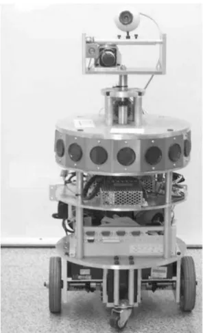
The developed visual tracking system is implemented on the self-made prototype home robot H2. The home robot H2 is equipped with an on-board industrial PC (IPC), which is connected to the internet via a wireless local area network (LAN) card. On top of the robot body, a two-degree-of-freedom robotic head was installed with a complementary metal-oxide semiconductor (CMOS) camera on top of it. The
Fig. 1 From view of home robot H2 camera is connected to the IPC via a universal serial
bus (USB) port. For building environmental map and
collision avoidance, H2 is equipped with 12 ultrasonic of image preprocessing. Module 2 performs the facial feature searching and localization. This module is sensors. Two stand-alone motor control modules are
provided for servo control of robotic head motors responsible for searching the ellipse contour and skin colour region. It determines the maximal likelihood and body wheel motors. The motor control module
consists of a self-designed motor control card and a from the candidates. The result of this module is used to calculate the desired angular position of the pan servo driver. The motor control card is based on a TI
TMS320F240 digital signal processing (DSP) chip, and tilt motors of the robotic head. Module 3 is the robotic head motion controller. The controller which handles two d.c. servo motors. The DSP chip
communicates with the on-board IPC via a serial port ensures that the pan and tilt motors move to the positions calculated in the previous sample instant. to receive motion commands. Figure 1 shows a
picture of the home robot hardware prototype. Module 4 is the robot pose estimation and human face measurement module. In this part, the size of The software structure of the home robot is
illus-trated in Fig. 2. The programming language used is the head is extracted and the robot pose is estimated. Module 5 is the robot navigation controller. From the C++ under a Windows XP environment. In this
structure, the visual tracking system is integrated information of the detected head size and robot pose, the controller decides the action of the robot body. with the robotic head control system and body
navigation system. The complete system consists of When an image is input into the system, module 1 works to obtain the edge and skin colour image. Then five modules. Module 1 is the image preprocessing
module. For skin colour segmentation, hue and the interested human head is searched and localized. If no human head is found in the image, the system saturation information of the HSV (hue, saturation,
and brightness value) colour space is used. This then restarts in order to acquire new image input. Otherwise the system calculates the pan angle h
pan module transforms a red–green–blue (RGB) colour
image into a grey-level image and an HSV colour and tilt anglehtiltin order to control the robot head. At the same time, module 4 estimates robot pose and space image separately. Edge detection and skin
Fig. 2 System architecture of the visual tracking system
of module 3. Finally, module 5 obtains the result of formed to the HSV colour space. The system seg-ments the skin colour pixels by using thresholds of module 4 to control the robot body. Thus the system
simutaneously controls the robot head and robot hue and saturation. The human head is found and localized subsequently.
body for visual tracking.
3 HEAD DETECTION AND LOCALIZATION 3.1 Head contour detection
An elliptic shape was adopted to model the human In the visual tracking system, the human head shape
head contour [8, 9]. The ratio of the long and short and skin colour information are utilized to search for
axes of the ellipse is selected to be 1.2. At each sample and localize the human head. An elliptical shape is
instant, at position (x, y), the average gradient magni-adopted to model the human head contour [8]. Using
tude is calculated around the perimeter of the ellipse. the ellipse model facilitates fast and effective human
If the average value is higher than a threshold, head searching. A bound box is employed to detect
the ellipse is then a candidate. The short axis of the skin colour inside the head region. For searching and
ellipse is set to a value between 30 and 50 pixels for localizing the human head, the system extracts edge
the system to capture a human face between 0.5 and and skin colour information of the image. To obtain
1.5 m away from the robot. The gradient magnitude the edge information, colour space transformation is
around the perimeter of an ellipsew
g(s) is calculated used to transform RGB colour space images to
grey-as level ones. A low-pass filter is then applied to reduce noise [12]. Finally, edge information is obtained using the Sobel algorithm. To obtain the skin colour
wg(s)=Ns1 ∑Ns i=1|gs(i)|
(1) information, the RGB colour space is also
trans-where gs(i) is the binarized intensity gradient value where wskinis the skin colour distribution factor, Ns denotes the number of pixels in the test region at perimeter pixel i of the ellipse represented by s.
Ns is the number of pixels on the perimeter of the represented by s=(x, y), Ex and Ey are, respectively, the long and short axes of the ellipse, andwskinis a ellipse and wg(s) is the average gradient magnitude
around the perimeter of the ellipse. The value ofw
g(s) value between 0 and 1. If wskinis equal to 0, there is no skin pixel in the bound box. Ifw
skinis equal to 1, is between 0 and 1.
all the pixels in the bound box are skin colour pixels. I
skinis the segmented skin colour image and
3.2 Skin colour segmentation
is a binary image. In the I
skinimage, if a pixel in (x, y) Skin colour is a useful feature and one of the most
is a skin colour pixel, then I
skin(x, y) is equal to 1; important characteristics of a human face. It is often
otherwise Iskin(x, y) is equal to 0. used to locate and track a human face. However, skin
At each sample instant, searching for a human colour is influenced by many factors. One is that
head is first performed in the image frame. Then the different people have different colour appearances.
average intensity gradient along the head boundary Previous studies show that such a difference can be w
gand the skin colour distribution of the interior of reduced using normalized RGB or HSV colour space
the head regionw
skinare calculated. The human head calculations. Another factor is lighting variations. The
position in the image is the maximum of the sum of influence of lighting can also be reduced by using w
gandwskin. This procedure is given by colour space approaches. In this design, a bound box
s*= max
siµS [wg(si)+wskin(si)] (3) is set up to detect skin colour inside the head region.
The height and width of the bound box are set to be
where s* denotes the obtained head location, Si double those of the long and short axes of the ellipse.
denotes the candidate head location, and S is the The skin colour distribution factor w
skin is obtained search space in the image. using the expression
The rotation angles of pan and tilt motors are determined by the difference between the estimated wskin=Ns1
C
x+Ex∑ i=x−Ex ∑ y+Ey j=y−EyIskin(i, j)D
(2)head position and the centre position of the image
frame 4 VISUAL TRACKING CONTROLLER
The purpose of the visual tracking controller is to hpan=xk−xcypan , htilt=yk−yc
ytilt (4) ensure that the camera tracks the intended human face by controlling the pan and tilt motors of the where (x
c, yc) is the centre point of the image frame, robotic head. An image-based control scheme is pro-which is (160, 120), and (x
k, yk) is the head position posed in this paper to perform the image tracking in the image plane. In this design,ypan andytiltare,
control. This design uses image features directly. It respectively, the scaling factors of pan and tilt
does not need to compute the relative positions and rotations. These two scaling factors are determined
orientations of the target in Cartesian coordinates. using a calibration procedure, which is presented in
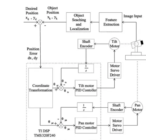
The block diagram of the control system is illustrated section 4.1. The angleshpanandhtiltare the inputs of
in Fig. 3. The system consists of two parts: an image the pan and tilt motors of the robot head control
feedback outer loop and servo inner loops. system, which rotates the pan and tilt motors to the
In the first part, the outer control loop was desired angle via, respectively, the pan and tilt PID
designed based on image feature feedback. An image controllers. The controllers thus ensure that the
is read into the system and the system extracts the camera observes the direction of the tracked human
head. head shape and skin colour features to search for
Fig. 4 Step responses of the pan and tilt motors: (a) and (b) are the step responses and the tracking response of the pan motor; (c) and (d) are the step responses and the tracking response of the tilt motor
the location of the human head. In the second part, input needs a longer time to reach the steady state. Figure 4(b) shows the tracking performance two servo control loops are designed for the pan and
tilt motors. A two-axis DSP-based motion control of the pan motor. The trajectory is a square wave of peak values 15° and −15°. The period is 700 ms. card is employed to complete the inner control of
each axis of the robot head. The system transforms Figures 4(c) and (d) show, respectively, the step responses and the tracking performance of the tilt the position error in pixels to the rotation angle in
degrees. The lower-level servo controller drives the motor. From the experimental results, it can be seen that for a 10° angular displacement the rise-time of pan and tilt motors to ensure that the object is in
the centre of the image. Figure 4(a) shows the step the tilt motor is 105 ms and that of the pan motor is 60 ms. The difference is mainly because the gear ratio response of the pan motor controller. The step inputs
are 1°, 5°, 10°, 15°, and 20° respectively. From the of the tilt motor is 300 : 1 and that of the pan motor is 65 : 1.
experimental results, it can be seen that a larger
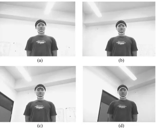
Fig. 5 The original image, edge image, and skin colour image of the static head tracking results: (a) head in front of the camera, (b) head moves from right to left, (c) head tilts up and down, (d) head turns left and right
4.1 Image calibration and coordinate angles of the tilt and pan motors respectively, andy
tiltandypanare the resultant scaling factors
transformation
of the tilt and pan motors respectively. The The purpose of image calibration is to determine the
calibrated scaling factors are obtained as follows: scaling factor between the pixels in the image plane
pan (horizontal) scaling factory
pan=5.525 pixels/ and the motor control angles for controlling the degree if the horizontal angle is less than 15°; pan and tilt motors. Through a comparison with the
ypan=6.67 pixels/degree if the horizontal angle is original image and a moved image caused by rotation greater or equal to 15°; and tilt (vertical) scaling of the motors, the change of pixels can be obtained
factory
tilt=4.326 pixels/degree. Practical measure-in the image plane. Given the rotation angular
dis-ment shows that the average error in the image placement, the scaling factor can be obtained from
plane is 7.18 pixels in the horizontal direction and calibration measurements. The procedure for image
7.25 pixels in the vertical direction. calibration is described below.
1. Rotate the pan and tilt motors of the robot head 4.2 Robot body motion control to various angles.
For the home robot, the visual tracking system not 2. Compare the resultant calibration pattern image
only tracks a person by controlling the robotic head with the original image.
but also pursues the person by controlling the robot 3. Determine the pattern differences in pixels of the
body. There are three navigation modes for the pan and tilt motors.
robot body. 4. Calculate the scaling factor using
1. Pursuing a person. When the robot detects a ytilt=W yi−tiltn , ypan=W yi−pann (5) person in front of it and the distance between the person and the robot is greater than a threshold value, the robot will then move towards the where n is the number of rotation times in the
calibration test, yi−tilt and yi−pan are the scaling person. The distance is adaptively determined according to the size of the object.
factors of pixels and degrees for each rotated
2. Keeping a distance with a person. When the dis- detected on the right side of the image. The head moved from right to left, as depicted in Fig. 5(b). In tance between the robot and the person is smaller
than a threshold value, the robot moves backwards the figures, ellipse contours indicate that the head was tracked. Figures 5(c) and (d) show the tracking to keep a preassigned distance with the person.
3. Body orientation correction mode. The purpose results as the head tilted up and down, and turned left and right. It is observed that the ellipse symbol of this function is to amend the angle between
the robotic head and the robot body. It works to always followed the human head.
The purpose of the second experiment is to show align the robot in the direction of the person.
that the two-degree-of-freedom robot head can track a person walking in front of the robot. Figure 6 shows that a person walked horizontally from the right side
5 EXPERIMENTAL RESULTS
to the left side of the robot and the robot head moved to follow the person. In Fig. 6(a), the person stood
5.1 Face tracking experiments
on the right side of the robot and the robot head The system was first tested for several poses with- turned right to follow the person. In Figs 6(b) to (d) out moving the robot body. Figure 5 illustrates the the person kept moving to the left side and the robot
head followed. experimental results. In Fig. 5(a), a human face was
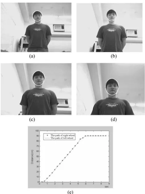
Fig. 7 (a) The robot detects a person in front of it; (b), (c), (d) the robot moves towards the person; (e) recorded trajectories of the right and left wheels
5.2 Robot tracking experiments Fig. 7(a), the robot detected the person and moved towards him. In Figs 7(b) to (d), the robotic head In this part, the coordination of the robotic head and tilted the camera to face the person as it approached robot body is demonstrated. Figure 7 shows that a
him. Figure 7(e) shows the recorded trajectories of person stood about 170 cm in front of the robot. In the right and left wheels. The robot moved forward 90 cm and then stopped because it was close enough to the person.
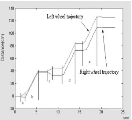
In the next experiment, a simple human–robot interaction is demonstrated. A person stood in front of the robot and moved forwards and backwards around the robot. The robotic head tracked the human head while the robot body followed the person. Figure 8 illustrates the motion trajectory of the person in the experiment. Figures 9(a) to (e) presents the tracked human image as observed by the robot in positions 1, 2, 3, 4, and 5 of Fig. 8 respectively. Figure 9(f ) shows that the robot moved close to the person and tilted the robotic head upwards. Figure 10 presents the recorded trajectories of the wheels. In time intervals a, c, and d of the recorded trajectories, the robot body rotated to face the person. In time intervals b and e, the robot
Fig. 8 The motion trajectory of the person in the robot
tracking experiment moved forwards to follow the person.
Fig. 10 The recorded trajectories of the experiment in Figs 8 and 9
6 CONCLUSION AND FUTURE WORK E009-027. The authors would like to thank Mr Kun-Ming Yan for his assistance in constructing the mobile robot. The suggestions and comments of A visual tracking system has been designed and
implemented for a home robot to follow a person. referees for improving this paper are gratefully acknowledged.
Image processing algorithms using skin colour and head shape features have been developed for facial feature searching and localization. A tracking
con-REFERENCES
troller is designed using an image-based approach for following a moving person. Experimental results
1 Baltus, G., Fox, D., Gemperle, F., Goetz, J.,
show that the robot tracks a person first using its Hirsch, T., Margaritis, D., Montemerlo, M., head motion and then using a combined body and Pineau, J., Roy, N., Schulte, J., and Thrun, S. head motion as the person moves continuously. The Towards personal service robots for the elderly. In real-time performance is, however, still not satis- Proceedings of the Workshop on Interactive Robots and Entertainment (Wire-2000), Pittsburgh, USA, factory. In the future, a dedicated image-processing
2000. board using a DSP chip will be added to the robot
2 Ghidary, S., Nakata, Y., Takamori, T., and to improve the real-time tracking performance. On
Hattori, M. Localization and approaching to the
the other hand, a more robust image processing
human by mobile home robot. In Proceedings of algorithm will be investigated to cope with the vari- the 9th IEEE International Workshop on Robot and ation of lighting conditions during tracking. It will Human Interactive Communication, Osaka, Japan, also be interesting to add a face recognition function 2000, pp. 63–68.
3 Feyrer, S. and Zell, A. Tracking and pursuing
to the home robot such that it can recognize a family
persons with a mobile robot. In Proceedings of the member and interact with him or her accordingly.
International Workshop on Recognition, Analysis, and Tracking of Faces and Gestures in Real-Time Systems, Corfu, Greece, 1999, pp. 83–88.
ACKNOWLEDGEMENT 4 Schwerdt, K. and Crowley, J. L. Robust face tracking
using color. In Proceedings of the Fourth IEEE Inter-This work was supported by the National Science national Conference on Automatic Face and Gesture
Recognition, Grenoble, France, 2000, pp. 90–95. Council of Taiwan, under the grant NSC
91-2213-5 Wang, Y. and Yuan, B. A novel approach for human APPENDIX
face detection from color images under complex
background, Pattern Recognition, 2001, 40(10), Notation 1983–1992.
6 Spors, S. and Rabenstein, R. A real-time face tracker Ex long axis of an ellipse for color video. In Proceedings of the 2001 IEEE Ey short axis of an ellipse International Conference on Acoustics, Speech, and g
s binarized intensity gradient value Signal Processing, Salt Lake City, USA, 2001, l
d distance in world coordinate system pp. 1493–1496.
I
skin binarized skin colour value after
7 Lin, C. H. and Fan, K. C. Triangle-based approach
segmentation to the detection of human face, Pattern Recognition,
n number of rotations 2001, 34(6), 1271–1284.
8 Birchfield, S. An elliptical head tracker. In Pro- Ns number of pixels in the head region ceedings of the Thirty-First Asilomar Conference on represented by s(x, y)
Signals, Systems and Computers, Pacific Grove, USA,
Ns number of pixels along the perimeter of
1997, pp. 1710–1714. an ellipse
9 Birchfield, S. Elliptical head tracking using intensity
s perimeter of an ellipse gradients and color histograms. In Proceedings of
s* head location the IEEE Computer Society Conference on Computer
x
c, yc centre point of the image frame Vision and Pattern Recognition, Santa Barbara, USA,
1998, pp. 232–237. x
d, yd desired target location in the image
10 Jordao, L., Perrone, M., Costeira, J. P., and Santos- plane Victor, J. Active face and feature tracking. In x
k, yk head location in the image plane Proceedings of the International Conference on
Image Analysis and Processing, Venice, Italy, 1999, h
pan pan rotation angle pp. 572–576.
htilt tilt rotation angle
11 Chaouke, B., Tairi, H., Masmoudi, L., and
wg average intensity gradient
Radouane, L. PI controller for visual tracking:
wskin skin colour distribution in an ellipse further results. In Proceedings of OCEANS ’99
MTS/IEEE on Riding the Crest into the 21st Century, region Seattle, USA, 1999, pp. 1480–1485. y
pan scaling factor of pan rotation
12 Gonzalez, R. C. and Woods, R. E. Digital image y
tilt scaling factor of tilt rotation processing, Second Edition, 2002 (Prentice-Hall,