Design of a fuzzy controller for the adaptive control of
WEDM process
Y.S. Liao
*, J.C. Woo
Department of Mechanical Engineering, National Taiwan University, No. 1 Roosevelt Rd. Sec. 4, Taipei 106, Taiwan
Received 5 July 1999; accepted 7 April 2000
Abstract
This paper addresses the design of a fuzzy controller for the control of the wire electrical discharge machining (WEDM) process. The power consumption and short circuit ratio are chosen as control para-meters. Incorporated with pulse trains analysis and experience, fuzzy rules for the control of the WEDM process are formulated. A DSP-based on-line pulse monitoring system is developed, and the fuzzy control system is implemented on a PC-486. In the developed control system, a reference power level is specified beforehand, and feed is adjusted according to the computed actual machining power. Off time is regulated automatically so that short circuit ratio will not exceed a specific value. Fine tuning of feed and pulse off-time is conducted if the variation in the average ignition delay off-time is too large. Experiments show that the developed control strategy results in very satisfactory transient and steady state responses as compared with a conventional control scheme. 2000 Elsevier Science Ltd. All rights reserved.
1. Introduction
Wire electrical discharge machining (WEDM) is a manually dependent process since many machining parameters are determined by experienced operators in practice. With the trend of automation and the need for parts with intricate shapes in modern industry, an adaptive control system which can regulate machining conditions automatically during the machining process has become more and more important in the current use of WEDM.
Conventionally, the average gap voltage is employed for the servo control of the WEDM pro-cess. Since comprehensive information related to the gap condition is not available, this method does not result in satisfactory performance. Several studies on the adaptive control of the WEDM
* Corresponding author. Tel.:+886-2-362-6431; fax:+886-2-363-1755.
E-mail address: [email protected] (Y.S. Liao).
0890-6955/00/$ - see front matter2000 Elsevier Science Ltd. All rights reserved. PII: S 0 8 9 0 - 6 9 5 5 ( 0 0 ) 0 0 0 3 6 - 5
process have been proposed over the years, see for examples [1–3]. However, there are only a few studies on the adaptive control of the WEDM process. An expert system has been developed for the control of the WEDM process [4], but it is not satisfactory for on-line control due to the large amount of computation resulting from the slow learning speed. Fuzzy logic has been applied to the adaptive control of the WEDM process in our previous study [5]. Stable and high speed machining can be achieved while at the same time wire rupture can be prevented, but, similar to other approaches, it still needs a large quantity of data (reference point of the control system), and many experiments have to be conducted beforehand. In this paper, two parameters related to machining speed and stability are derived. Together with the results from pulse trains analysis, a new fuzzy control system for the WEDM process is proposed and implemented. Experiments are conducted to verify the performance of the proposed control system.
2. Pulse discriminating system and pulse trains analysis
An on-line pulse discriminating system, as shown in Fig. 1, has been developed. This system consists of two parts: a pre-processor circuit, and a DSP-based pulse analysis circuit. The former is used to isolate discharging noise, while the latter is designed to record and discriminate the ignition delay time of each pulse. Information on the control parameters (explained in the next section) in a sampling period is sent to an external PC for process monitoring and on-line control. Experiments without the servo feed control have been conducted, and the behavior of pulse trains under various conditions was analyzed in our previous study [6]. Some of the analysis results are recapitulated here. Let the short, arc or normal ratio be defined as the proportion of
that particular type of discharge in a specific sampling period. It is found that the short ratio, arc ratio and discharge frequency increase, while the normal ratio and the average ignition delay time decrease with an increase in table feed. As pulse off-time is decreased, the short ratio is reduced, the average ignition delay time and normal ratio are increased, while the variations in the arc ratio and discharge frequency are insignificantly small.
3. Control parameters
In machining a workpiece of height H (mm) with a table feed of Fd (mm/s), let the pulse on-time, discharge voltage and peak current be represented by T (s), V (V) and I (A). If the discharge frequency is given by Fq (kHz), then the total power consumption W in watts for the current of a triangular wave form can be expressed as:
W⫽1
2(2TI)V⫻Fq⫽V⫻I⫻T⫻Fq (1)
In the above equation 2T is used. This is because the total discharge time is 2T for a pulse on-time of T for a current having a triangular shape wave form. Let the resulting kerf or groove width be denoted by G (mm), then the specific discharge energy uo, defined as the energy required to remove a unit volume of metal in joules per cubic millimeter, can be written as
uo⫽
W
GH×Fd (2)
Fig. 2a, b shows the variations in G and uowith respect to pulse off-time and on-time, respectively. Here G is measured under a toolmaker’s microscope. It can be seen from these figures that an increase in pulse off-time or a decrease in on-time results in a reduction in groove width, and the variation in G with on-time is larger than that with off-time. On the other hand, the specific discharge energy remains constant, irrespective of the change in pulse off-time and on-time. The denominator in Eq. (2) is the metal removal rate. Hence, taking power consumption as a control parameter is equivalent to setting the metal removal rate. It is noted that power consumption is independent of on-time when the metal removal rate is kept constant. However, there exists an inverse relationship between discharge frequency, a control parameter widely employed for control purposes, and on-time, under the same control objective. Hence, the use of power consumption as a control parameter is not only physically more meaningful, but the reference value is also more easily set in practice.
The arc and short ratios are defined as the proportion of the numbers of arc discharge, and the numbers of short circuit in a sampling time, respectively. An abnormal ratio is the sum of the arc and short ratios. The arc, short and abnormal ratios under full speed cutting conditions are shown in Fig. 3. In the figure, the abscissa represents different machining settings. Taking 5F5F26 as an example, these three numbers represent the settings of on-time, off-time and table feed rate. Their scales are 0.1 µs, 1.6µs, and 0.1 mm/min, respectively. Hence, on-time is 0.5µs, off-time is 8 µs, and the table feed rate is 2.6 mm/min in this case. It can be seen from this figure that there is a large variation in the arc ratio and abnormal ratio, but the variation in the short ratio is comparatively smaller; its value ranges from 0.37 to 0.42. Physically, short circuits occur when
Fig. 2. Variations in groove width and specific discharge energy with (a) pulse on-time, and (b) pulse off-time.
there is contact between the wire and the work material. The probability of contact between the wire and the workpiece is expected to be the same under full speed cutting conditions. Hence, the short ratio remains almost unchanged under full speed cutting conditions. A similar result was also reported by Kinoshita et al. [7]. Considering this property, the short ratio is chosen as another control parameter. Because there is a larger increase in the short ratio when the process is in the vicinity of full speed cutting conditions, the target of the short ratio is set to 0.3 so that the process can be operated under high cutting speed but within the safe region. Moreover, because the system becomes less stable when there is a drastic change in the average ignition delay time, the increment in the average ignition delay time is selected as another output variable in order to retrieve information on the process.
Fig. 3. Arc ratio, short ratio, and abnormal ratio under full cutting speed for various machining settings.
The principle of the proposed on-line control system is summarized as follows. For a selected pulse on-time, the table feed rate is increased so that the preset power reference value can be reached. The short ratio reference value is mainly used for the adjustment of the pulse off-time. If the change in the average ignition delay time is too large, the table feed rate and pulse off-time are modified accordingly so that a stable machining process can be maintained.
4. Adaptive fuzzy controller of the WEDM process
The adaptive fuzzy controller is given in Fig. 4. According to the control objective, the input and output variables are defined as follows:
e1⫽(Yr1⫺Y1(kt))GE1 (3)
e2⫽(Yr2⫺Y2(kt))GE (4)
ce⫽(Td(kt)⫺Td((k⫺1)t))GCE (5)
⌬u1⫽F1(e1, e2, ce) (6)
⌬u2⫽F2(e1, e2, ce) (7)
In the above equations, notations Yr1and Y1 are the reference power and actual power consump-tion, respectively. Yr2 and Y2 are the reference short ratio (taken as 0.30) and the short ratio measured during machining. Some experiments are proceeded with a different on-time setting. The maximum cutting speeds for a fixed on-time can be acquired by adjusting the off-time and feed manually, so the reference Yr1 of a different on-time can be estimated in advance by the use of Eq. (1). Td(kt) and Td((k⫺1)t) are current and previous average ignition delay times, respect-ively. GE1, GE2, and GCE are scaling factors, and GE1=0.00165, GE2=18, and GCE=0.6 in our case. Seven linguistic fuzzy variables for fuzzification of the input terms e1 and e2 are specified. They are positive big (PB), positive medium (PM), positive small (PS), zero (ZO), negative small (NS), negative medium (NM), and negative big (NB). Five linguistic sets namely PB, PS, ZO, NS and NB are specified on the domain of ce. The membership function of linguistic values of input (i.e. e1, e2, and ce) of the controller is an isosceles triangle-shaped function because of convenient manipulation. F1(.) and F2(.) stand for the nonlinear relationship of the fuzzy control-ler. ⌬u1 and⌬u2 are the changes in the feed control action and the pulse off-time control action, respectively. Seven linguistic fuzzy variables are employed for the output variables as well, but the bar shape membership function is used to alleviate computation load. Based on pulse trains analysis [6], the operator’s experience and the expert’s knowledge, fuzzy rules can be designed according to the following principles:
(i) When the power consumption and short ratio are significantly lower than the preset refer-ence values — a rapid increase in the cutting speed is the main operating objective at this stage. Hence, pulse off-time is kept unchanged while table feed rate is increased as much as possible.
(ii) When the power consumption is significantly lower than the reference value, and the short ratio is close to the reference value — pulse off-time should be decreased first to reduce the short ratio. By so doing, there is more room for an increase in power. Hence, the machining speed can be increased further while at the same time eliminating the action of the withdrawal of the wire due to the short circuit protection function of the machine. (iii) When the power consumption approaches the preset critical value and the short ratio is significantly lower than the reference value — pulse off-time is increased so that the appropriate gap width is maintained. Since the groove width is reduced slightly (due to an increase in pulse off-time), table feed rate can be increased slightly without the need for increasing machining power.
Table 1 Fuzzy rules e1=PB ce ce e2 PB PS ZO NS NB e2 PB PS ZO NS NB PB PB PB PB PB PB PB ZO ZO ZO ZO ZO PM PB PM PM PM PS PM NB NM NM NM NS PS PM PS PS PS ZO PS NB NB NB NB NM ZO PS ZO ZO ZO ZO ZO NB NB NB NB NM NS ZO NS NS NS NM NS NB NB NB NB NM NM NM NM NM NM NB NM NB NB NB NB NM NB NB NB NB NB NB NB NB NB NB NB NB e1=PM ce ce e2 PB PS ZO NS NB e2 PB PS ZO NS NB PB PB PM PM PM PS PB PB PM PM PM PS PM PB PM PM PM PS PM NM NS NS NS ZO PS PM PS PS PS ZO PS NB NM NM NM NS ZO PM PS PS PS ZO ZO NB NB NB NB NM NS ZO NS NS NS NM NS NB NB NB NB NM NM NS NM NM NM NB NM NB NB NB NB NM NB NB NB NB NB NB NB NB NB NB NB NB e1=PS ce ce e2 PB PS ZO NS NB e2 PB PS ZO NS NB PB PM PS PS PS PS PB PM PS PS PS PS PM PM PS PS PS ZO PM PM PS PS PS ZO PS PM PS PS PS ZO PS ZO ZO ZO ZO ZO ZO PS PS PS PS NS ZO ZO ZO ZO ZO ZO NS ZO ZO ZO ZO NM NS ZO ZO ZO ZO ZO NM NS NS NS NS NM NM NS NS NS NS NM NB NB NB NB NB NB NB NB NB NB NB NB e1=ZO ce ce e2 PB PS ZO NS NB e2 PB PS ZO NS NB PB PS PS PS PS ZO PB PM PM PM PM PS PM PS PS PS PS PS PM ZO ZO ZO ZO ZO PS ZO ZO ZO ZO NS PS ZO ZO ZO ZO ZO ZO ZO ZO ZO ZO NS ZO ZO ZO ZO ZO ZO NS ZO ZO ZO ZO NS NS ZO ZO ZO ZO ZO NM NM NM NM NM NB NM ZO ZO ZO ZO ZO NB NB NB NB NB NB NB NM NM NM NM NM
Table 1 (continued) e1=PB ce ce e2 PB PS ZO NS NB e2 PB PS ZO NS NB e1=NS ce ce e2 PB PS ZO NS NB e2 PB PS ZO NS NB PB NS NS NS NS NM PB PM PM PM PM PS PM ZO ZO ZO ZO NM PM PS PS PS PS ZO PS NS NS NS NS NS PS ZO ZO ZO ZO ZO ZO NS NS NS NS NS ZO ZO ZO ZO ZO ZO NS NS NS NS NS NM NS ZO ZO ZO ZO ZO NM NM NM NM NM NB NM NS NS NS NS NM NB NB NB NB NB NB NB NB NB NB NB NB e1=NM ce ce e2 PB PS ZO NS NB e2 PB PS ZO NS NB PB ZO NS NS NS NM PB PB PB PB PB PM PM ZO NS NS NS NM PM PB PB PB PB PM PS NS NM NM NM NB PS PB PM PM PM PS ZO NS NM NM NM NB ZO PB PM PM PM PS NS NM NB NB NB NB NS PB PM PM PM PM NM NM NB NB NB NB NM PB PM PM PM PM NB NB NB NB NB NB NB ZO ZO ZO ZO ZO e1=NB ce ce e2 PB PS ZO NS NB e2 PB PS ZO NS NB PB NB NB NB NB NB PB PB PB PB PB PB PM NB NB NB NB NB PM PB PB PB PB PB PS NB NB NB NB NB PS PB PB PB PB PB ZO NB NB NB NB NB ZO PB PB PB PB PB NS NB NB NB NB NB NS PB PB PB PB PB NM NB NB NB NP NB NM PB PB PB PB PB NB NB NB NB NB NB NB PB PB PB PB PB
(iv) When both the power consumption and the short ratio are close to or equal to the preset reference values — the control objective has been reached under these conditions. Since the discharging process is very sensitive to a change in pulse off-time, and because the pulse off-time of a commercial WED machine cannot be adjusted in one step, the table feed rate is adjusted if regulation of the process variable is called for.
the critical reference value — the table feed rate should be reduced rapidly, and the pulse off-time should subsequently be reduced so that the short ratio can be decreased immedi-ately. Recovery of the process to the stable state is the first priority under this machin-ing condition.
(vi) When the power consumption is higher than the critical reference value while the short ratio is lower than the reference value — this is a situation where the operating machine power is overly high due to a large pulse on-time setting and a high table feed rate. Since there is a risk of the wire breaking, an increase in the pulse off-time and a reduction in the table feed rate should be conducted immediately.
(vii) Whenever both of the power consumption and the short ratio are significantly higher than the critical reference values — both wire breaking and the withdrawal of the wire could take place under these circumstances. Because the effect of the wire breaking is far more serious than that of the withdrawal of the wire, the same principle as that stated in principle (vi) is adopted.
Fuzzy rules are constructed according to these principles. A complete table of fuzzy rules is shown in Table 1. The left-hand side represents a change in the table feed rate, while the right-hand side shows a change in the pulse off-time. The max–min inference method and the center of area method are employed to perform the fuzzy reasoning on both the linguistic control rules and the defuzzification of the control action.
5. Experiments and results
A PC based iso-energy type WED machine is used for the experiments. The current wave form of this machine is a triangular shape with a slope of 380 A/µs. The sampling interval used is 60 ms. Four experiments are conducted to test the performance of the proposed control strategy. The machining parameters and controller parameters are given in Table 2. In the table, notations GU1 and GU2 are the scaling factors used in the calculation of ⌬u1 and ⌬u2, respectively, during the defuzzification of the output; their values are pre-determined by the experiments. As described
Table 2
Machining conditions and controller parameters used in the experiments
Machining parameters Controller parameters
Test no. OnFtime Wirespeed Wire tension Flushing GU1 GU2 Yr1 Yr2 pressure (µs) (m/min) (gf) (bar) ×0.01 ×0.001 ×0.44 (W) 1 0.5 9 1200 6 1 5 3800 0.3 2 0.7 9 1200 6 1 0.5 3800 0.3 3 0.7 9 1200 6 1 0.5 4800 0.3 4 0.9 9 1200 6 1 0.05 4800 0.3
previously, the pulse off-time can be adjusted to a more appropriate value automatically. A con-servative and long pulse off-time (24 µs) is chosen as the initial value for all experiments. The work material is SKD11 die steel, and its thickness is 50 mm.
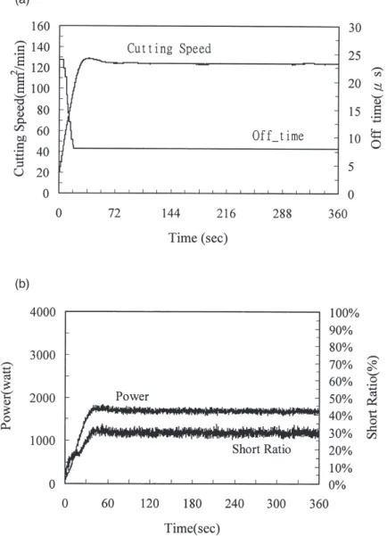
Variations in the inputs (feed and pulse off-time) and controlled output (power and short ratio) with respect to machining time for test no. 1 are shown in Fig. 5a, b. In the experiment the pulse on-time is 0.5 µs, the reference Yr1 is estimated by the use of Eq. (1), (e.g. for on-time=0.5 µs,
I=380 A/µs, V=220 V, Fq at high cutting speed is approximately 80 KHz, hence
W=(220)(190)(0.5×10⫺6)(80×103)=1762 W, or W=0.44×3800 W) and the total machining time is 360 s. It can be seen from Fig. 5 that machining power increases rapidly in accordance with the rapid increase in feed rate. As a result, the short ratio rises as well. Hence, the pulse off-time is
reduced to keep the short ratio at a preset value. The steady state is reached in about 45 s. The pulse off-time is changed from 24µs to an appropriate value of 8 µs. The transient time can be reduced at the expense of a slight overshoot if a larger gain is used instead. The stable machining speed is about 124 mm2/min. By checking with Fig. 2, this is about the highest cutting speed achievable for the pulse on-time of 0.5µs. It is also noted from Fig. 5a that the variation in the feed is very small (±0.01 mm/min). This implies that there is not much variation in the groove width and a good dimensional accuracy is obtained.
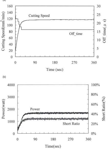
Machining conditions for test no. 2 are the same as for test no. 1, except the pulse on-time is replaced by 0.7µs. The results are given in Fig. 6a, b. From the start of the cutting process until it reaches steady state, the pulse off-time is changed from 24 to 16µs in about 36 s. The transient
time is shorter owing to less steps being taken in changing the pulse off-time. A very stable process is maintained as well. However, the cutting speed is about 117 mm2/min, which is a little slower than 124 mm2/min, the cutting speed obtained by test no. 1. This is attributed to a larger groove width resulting from a larger pulse on-time. Since the cutting speed is equal to H×Fd, it can be readily understood from Eq. (2) that for a given machining power, a larger groove width results in a slower cutting speed. A larger pulse on-time also leads to a rougher machined surface and a thicker disturbed layer [8]. Hence, it is advisable to use a small pulse on-time under the condition of the same achievable machining power. Similar results are obtained for test no. 3, and they are shown in Fig. 7a, b. A higher cutting speed of 143 mm2/min is achieved owing to a larger Yr1. However, it takes a longer time of 90 s to reach the steady state. The reason for this
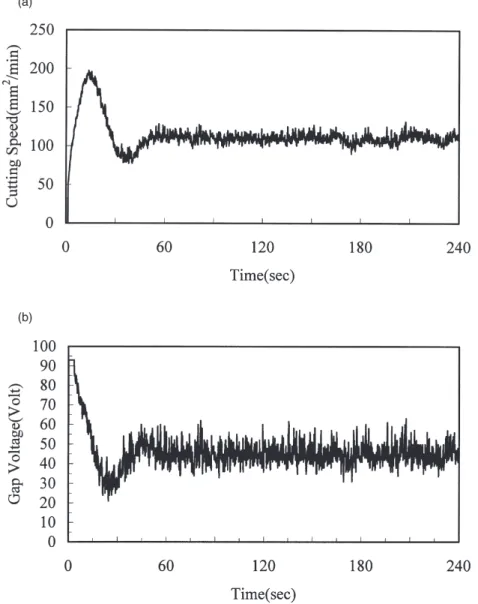
Fig. 8. PI control results for test no. 1: (a) cutting speed, and (b) gap voltage.
is because the cutting speed should be increased more in order to reach a higher reference power. This in turn results in a rise in the short circuit ratio. Hence, off-time should be decreased further to reduce the short ratio. Compared with test no. 2, it is concluded that a longer transient time is needed for the higher reference power under the same on-time setting. For the machine used in the experiments, the highest cutting speed achievable by the use of the conventional control method is about 125 mm2/min. This indicates that the developed controller can achieve a higher cutting speed. Test no. 4 results in a satisfactory performance as well. Similar to the comparison between test no. 1 and no. 2, the cutting speed attainable is lower, but the transient time is shorter. For comparison purposes, servo voltage control of the process, widely used in commercial machines, is carried out. The PI control algorithm is employed. The control results for the pulse
on-time and off-time of 0.5 and 8 µs, respectively (corresponding to the machining condition of test no. 1), are shown in Fig. 8a, b. The system reaches its steady state in 72 s, the cutting speed is 109 mm2/min, and the variation in feed is±0.29 mm/min. The use of other machining conditions results in a very similar performance as that shown in Fig. 8a, b. To reduce the transient time, a higher gain is also tested. Fig. 9a, b shows the results for test no. 1. As it can be seen, there is a large overshoot along with a shorter transient time (reduced from 72 s to about 60 s). The cutting speed is almost unchanged (about 110 mm2/min) and there is a large variation in feed rate at steady state (±0.415 mm/min). Hence, it can be concluded that the new fuzzy control strategy results in a superior performance compared to the conventional control scheme.
6. Conclusion
A DSP-based fuzzy logic control system for the WEDM process has been developed. The use of this control system results in a very satisfactory performance. The steady state can be reached in a very short period of time, and a stable and high cutting speed can be maintained. The developed control strategy is easy to be implemented and applied since the machining power associated with each pulse on-time setting is the only control parameter to be specified beforehand. The appropriate pulse off-time can be adjusted automatically. Because the number of the reference operating points is greatly reduced, it can be applied to a wide range of machining conditions.
References
[1] R. Snoeys, D.F. Dauw, J.P. Kruth, Survey of EDM adaptive control in electro discharge machining, Journal of Manufacturing Systems 2 (2) (1983) 147–164.
[2] M. Weck, J.M. Dehmer, Analysis and adaptive control of EDM sinking process using the ignition delay time and fall time as parameter, Annals of the CIRP 41 (1) (1992) 243–246.
[3] K.P. Rajurkar, W.M. Wang, Advances in EDM monitoring and control systems using modern control concepts, International Journal of Electrical Machining 2 (1997) 1–8.
[4] W. Dekeyser, R. Snoeys, M. Jennes, Expert system for wire cutting EDM, based on pulse classification and thermal modeling, Robotics and Computer Integrated Manufacturing 4 (1/2) (1988) 219–224.
[5] M.T. Yan, Y.S. Liao, Adaptive control of the WEDM process using the fuzzy control strategy, Journal of Manufac-turing Systems 17 (4) (1998) 263–274.
[6] Y.S. Liao, J.C. Woo, The effects of machining settings on the behavior of pulse trains in the WEDM process, Journal of Material Processing Technology 71 (1997) 433–439.
[7] N. Kinoshita, M. Fukui, H. Shichida, G. Gamo, Study on E.D.M. with wire electrode; gap phenomena, Annals of the CIRP 25 (1) (1976) 141–145.
[8] L.C. Lee, L.C. Lim, V. Narayanan, V.C. Venkatesh, Quantification of surface damage of tool steels after EDM, International Journal of Machine Tools and Manufacture 28 (4) (1988) 359–372.