Iterative Capacity Allocation and Production Flow Estimation
for Scheduling Semiconductor Fabrication
Shi-Chung Chang, Loo-Hay Lee, Lee-Sing Pang Department of Electrical Engineering
National Taiwan University Taipei, Taiwan, R.O.C.
e-rnail: [email protected]
Fax: 886-2-363-8247
A B S T R A C T
This paper presents an effective algorithm of determining daily production targets and the corresponding machine capacity allocation for semiconductor wafer fabrication. The algorithm adopts an iterative scheme and each iteration consists of two modules: the proportional Target Generation and Machine Allocation (TG&MA) and the Stage of Penetration Estimation Algorithm (SOPEA).
In TG&MA, machine capacities are allocated to processing different types of products at various stages in proportion t o
their respective available workloads. With the capacity allocated to each product type, SOPEA then applies a recursive, deterministic queuing analysis to estimate the expected flow-in workload of a stage within a day. The flow-ins are fed into TG&MA for another iteration of capacity allocation. Field implementation of this algorithm has demonstrated significant effects on production move increase, cycle time reduction and line balancing.
1. Introduction
Semiconductor wafer fabrication involves one of the world's most cornplex manufacturing processes. There may be tens of product types in a wafer fabrication plant (fab). The fabrication process of each type of wafers may require more than 100 fabrication stages, each consisting of a few fabrication steps; the whole process involves tens of delicate and expensive machines. As a type of wafers have quite a few (10 - 30 or so) layers of fabrication and stages between two layers of wafer bear some basic similarity, the production flow of each type of wafers may rccnter the similar sequence of machine groups from layer to layer in its
fabrication process. Owing the reentrant nature, wafers of different types as well as wafers of the same type but at differcnt layers of fabrication may compete for the finite capacity of a machine group. Complex and reentrant process flows and uncertainties of machine availability pose unique challenges to production scheduling of a fab for effective wafer-in-process (WIP) movement, machine utilization and on-time dclivery.
There have been many results o n scheduling and dispatching for wafer fabrication. Wein [Wei88] conducted simulation study and pointed out t h a t short interval
Thomas W.-Y. Chen, Yi-Chen Weng, Huei-Der Chiang, David W.-H. Dai Taiwan Semiconductor Manufacturing Co.
Hsin-Chu, Taiwan, R.O.C. Fax: 886-35-78 1-546
scheduling has a significant impact on fab performance. Bai et. al. [BSG90] and Conors et. al. [CFY92] adopted fluid network models for scheduling high volume fabs. Lu et a1
&RK94]
analyzed several distributed schedulinpjdispatching policies and identified two best policies for minimizing both the mean and the variance of cycle time. Liao et. al. LCK941 adopted a Lagrangian relaxation and network-based optimization approach for scheduling a pilot line. In&ea94], Leachman provided a survey of scheduling practices across six companies. These schedulers are mostly cutomized designs, involving some commercially available modules, the Kanban Logic, cycle time tracking mechanism, rule-based system, deterministic simulation, etc.
This paper presents an iterative algorithm for determining daily production targets and the corresponding machine allocation by product type and by production stage. The algorithm consists of two modules: the proportional Target Generation and Machine Allocation (TG&MA) and the Stage of Penetration Estimation Algorithm (SOPEA). The daily production target generation problem is first described in Section 2. Sections 3 and 4 present the
TG&MA and SOPEA algorithms respectively. Successes of their field application are then given in Section 5. Section 6 concludes the paper.
2 . D a i l y T a r g e t Generation a n d M a c h i n e
Allocation (TG&MA) Problem
Daily Target Generation and Machine Allocation is the production control function that determines for each product type the amount of wafers to be processed and the machine capacity allocated at each stage during a day. Under a given wafer release schedule, machine capacity, and initial WIP
distribution, it aims at multiple operation objectives such as 1.) meeting the monthly target output volume,
2.) balancing the production line,
3.) reducing WIP and cycle time,
4.)maximizing bottleneck machine utilization, and
5.jmeeting the due date and demanded volume of each Such a decision is difficult because of the complexity of IC fabrication.
production order.
To reduce the problem complexity to a comprehensible level and to focus on key issues, we make the foliowing assumptions and/or simplifications.
1. All product types are of the same priority. 2. The fabrication process of each part type is fixed.
3. Stage is adopted as the basic unit for describing process flows, where a stage of a product type is obtained by aggregating a few consecutive fabrication steps of the prodluct type.
4. All the stages of various fabrication processes can be arranged into a global sequence of totally J stages in a way that if a stage k precedes a stage k in one process, then stage k also precedes stage k' in the global stage sequence.5. The production unit is a wafer.
6. Each stage has a corresponding key machine groulp. As steps of a stage may require machines from different machine groups and different stages may also share the same machine groups, the machine group that has the highest ratio of processing time over number of machines among the steps in a stage is selected to be the key machine of the stage.
7. The aggregate capacity of a machine is defined b:y the average number of wafers it can process in a day; this value is obtained from empirical statistics without taking the factor of part mix into account.
8. Baiching effects at the diffusion and photolithography stages and setup times ae the implantation and photolithography stages are ignored.
9. Buffer space for WIP is large and can be considcrcd as infinite.
10. A desirable WIP level, called the "Standard W[P", is given for each stage.
To perform daily target generation and maclhine capacity allocation, the input data set includes
- the daily target output;
-
the process flow in terms of stages for each product type;- currcnt WIP level of each stage of a product;
- the &sired WIP level (called standard WE') of each stage;
-
processing time of every product at each stage,-
the key machine group for each fabrication stage and the- the capacity of each machine in a day defined as wafcrs per
- current machine status. number of machines in it; day; and
B'y using the above input data, the decision function is to decide daily production targets and machine allocation for each stage. The output targets and machine allocation are finalized in the daily production meeting, which are then given to the shop floor for execution. Operators carry out the actual dispatching of wafers so that the targets can bc
met.
3. Tlhe T C & M A Algorithm
TG&MA is an iterative algorithm that computes, for each wafer type at each fabrication stage, the target amount of wafers to be processed during a day. Given the desired outputs, WIP distribution and expected wafer flow-ins to each stage, each iteration of the TG&MA algorithm first
ignores the factor of finite machine capacity and computes an upper bound dcmand by type and slagc via a PUSH- PULL, procedure. The PUSH procedure generates demands in a waly that pushes the wafers at a stage to down stream stages except those needed for maintaining the standard WIP so that the unnccessary WIP is reduced and the throughput is maximized at the stage in a heuristic sense. The PULL procedure generates demands in a way that pulls for each stage the production flows from its up stream stages, attempting to maintain the standard WIP level of the stage and to meet the output demands of the line at the same time. The ~ipper bound demand by stage and type is the larger of the PUSH and PULL demands. Note that the upper bound dema.nds may not. be satisfied because of insufficient machine capacity or insufficient wafers for processing.
The factor of finite machine capacity is then considered. Since different typgs of wafers and different fabrication stages of a type may cornpete for the same type of machines, the capacity of a machine group is allocated proportionally to the ulppcr bound demands of stages that are competing for it and targets of individual types and stages are obtaincd. Finally, the target of each stage is further modified by considering initial WIP and how many wafers that may flow
into the stage from its up-stream stages within one day. To formalize iihe description of the algorithm, let us first define some notations.
Notations
H: ii:
0UTi:Lhe desired output amount of type-i wafers for the day;
JI: total number of stages in global sequence; j: stage index, j =1,
...
J;'N1P~j:thC WIP level of type-i parts at stage j at h e bcginning of the day;
Std-WIPij: the standard WIP level of type-i parts atstage j ;
flow-inij: number of type-i wafers flowing to stagej total number of part type;
part type index, i =1,
...
I;f&m its upstream stages during the day; average processing time of a type-i wafer at stage
j;
the set of all the immediatc up stream stages of stage j in various process flows;
amount of wafer start for the day; the totaJ number of machine groups; the machine group index, m=1, ..., M;
number of available machines in group m of the day;
capacity of a machine in group m in term of wafers per day;
index of machine group required by stage J;
the immediately up stream stage index for stage j of type i part.
Decision Variables
nj: number of machines allocated to process stage j for the day:
nij: number of machines allocated to process type-i parts at stage j -for the day;
Txgetij: number of type-i wafers leaving stage j to its down-stream stages.
ALGORITHM Step 0: Initialization
Input all the necessary data.
Set flow-inii = Ri for all i, and flow-inij = 0 for all i and j=2, ..., J.
Step 1: PUSH Do for j=1, ..., J Do for i=1, ..., I (WIP.. 1J
+
Flow-inij)tij C ( W 1 P i j+
Flow-inij)tij Pushij = Push. x 1 enddo enddoSet Pulla = OUTi, fori = 1 , . . . , I .
Do for j=J-1,
...,
I Step 2: PULL. .
Pushj = max[0, C ( W 1 P i j
+
Flow-inij)i
-
std-WIPj] Do for i=1, ..., I (WIPik,,+
Flow-inik JtljC
( WIPik,, + F l o w - i n k , , ) t i j ' Pull& = PUllj x 1J 1J 1J 'J 1J i enddo enddoSet UBDij = max(Pushij, Pullij) Step 3: Upper Bound Demand
fori = 1 ,..., I andj = 1 ,..., J.
Step 4: Target Generation and Machine Allocation Do for all i and
UBDij x tij Targeti, = Min (
C U B D ~ ~ ~
x C m . , x t . . U J j' with m ., = m . J J WIPij+
Flow-inij) Targetij x N m . niJ =c,
J j enddoIf the targets differ from the targets of the previous iteration by less than a preset small amount, then stop. Step 5 : Convergence Check
Step 6: Flow-in Update Do for i=1,
...,
IUpdate Flow-inij for j = l , ..., J under the targets of this iteration by using the SOPEA algorithm.
enddo
Go to Step 1 for the next iteration.
4. Stages of Penetration Estimation Algorithm
(S O P E A )
In this Section, an algorithm (SOPEA) is proposed to estimate how many stages that the initial WIP at each stage may go through after one day, which in turn is used to estimate the amount of flow-in wafers of each stage during a day. The key idea of SOPEA is that once the capacity allocation (nij) is obtained in TG&MA, individual production flows of different part types are essentially independent from each other. We therefore focus on analyzing a single type of wafer flow and develop a
deterministic queuing analysis for it. In our analysis, we assume that the wafers at a stage are processed on a FIFO basis. The part type index i is omitted in the following derivations for simplicity of presentation.
Consider the production flow between stage j to stage k (k > j ) as shown in Figure 1, where Tjk is the cycle time needed for the last piece of WIPj to finish processing at stage k. SOPEA defines a recursive algorithm for computing Tjk by using Tj(k-1) and TO+l)k based on the
following relationship. Two Stage Case ( k = j + l )
If WIPjtj/nj 5 [(WIPj - l)+WIPj+1]tj+l/nj+l, then Tjfi+l> = (WIPj+WIPj+l)tj+l/nj+l; else Tj(j+l) = WlPjtj/nj + tj+l/nj+l. If Tj(k-1) 5 T(j+l)k + (WIPj - l)tk/nk, then Tjk = TCj+l)k
+
WIPjtk/Ilk; else Tjk = Tj(k-1)+
tk/nk. General CaseNote that we can start with computing Tj(i+l> for j = 1,
...,
J-1 by applying the two-stage case formula. Then we can compute Tjfi+d) for j = 1,
...,
J-d, where d is increased from 2 to J- 1, by applying the general case formula with Tj(j+d-1) and T(j+l)fi+d> computed. Such a procedure geneiates all the Tjk's for 15 j < k 5 J. 'Interested readers may refer to Section 4.2 of [Wan941 for more details.
The amount of wafers that may flow into a stage j during a day can be easily computed by adding up the WIPs of stage j's uptream stages that has Tj'j 5 24 hours, i.e.,
Flow-in.. =
c
WIPij.,1J
j' E A . .
?I
where Aij
=
(j'l j' a stage of type i process flow,j' < j and Tjlj 5 24hrs).
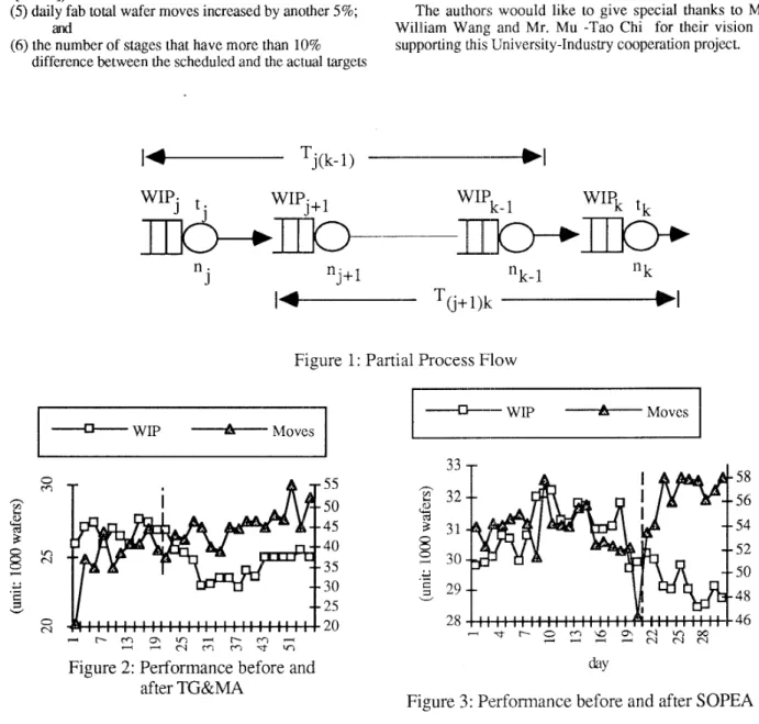
was reduced by about 10%. 5. Field Implementation Results
VI. Concludiing Remarks
A TG&MA module using an empirical rule for
esximating flow-ins instead of SOPEA was first
implemented in the field. Comparing the fab performance before and after the implementation, we observed significant improvements (Figure 2 and Lea941):
(1) overall fab WIP declined by 8%;
(2) daily fab total wafer moves increased by about 20%; (3) average cycle time per layer fell from 3.25 to 2.96
(4)
the average +2 sigma fell from 4.63 to 3.68. days;After integrating SOPEA with TG&MA in a later time, further improvements were immediately observed (Figure 3 mid -941):
( 5 )
daily fah total wafer moves increased by another 5 % ; and(6) the number of stages that have more than 10% difference between the scheduled and the actual targets
The TG&M[A and SOPEA algorithm presented in this paper combines production flow modeling, empirical rules, proportional resource allocation and deterministic queuing analysis into an effective target generation and machine capacity allocation tool for a semiconductor fab. F'reliminary analyses of its convergence and line balancing properties [C@W95] are consistent with our observations from its field implementation. It has also been extended to weekly and monthly target generation [Wan94].
7111. A c kn o w 1 edge m e n t s
The authors woould like to give special thanks to Mr. William Wang and Mr. Mu -Tao Chi for their vision in supporting this University-Industry cooperation project.
WIqi
t ;n j
"j+l
"k-1
"k
I
--
T(j+l)k
1
-Figure 1: Partial Process
Flow
--D---- WIP -Moves -WIP -Moves ^ ^ 55 50 45 40 35 30 - c - m
? - + 2 s z s q ;
Figure 2: Performance before and
after TG&MA
5 5 32 31 30 29 28 58 56 54 52I
't'
50 48 46Figure 3: Performance before and after SOPEA
References:
[BSG90] S . Bai,
N.
Srivantsan, and S. Gershwin, "Hierarchical Real-Time Scheduling of a Semiconductor Fabrication facility,"Proceedings of the 9 t h IEEE International Electronics Manufacturing Technology Symposium, Washington D.C., October 1990.[CCW95] S . Chang, W. Chan, T. Wang, C. Chang,
"Proportional Machine Allocation and Line Balancing in a Re-entrant Line," Proceedings of the Conference on Emerging Technology for Factory Automation, Paris, France, Oct. 1995.
[CFY92] D. Connors, G. Feigin, and D. Yao, "Scheduling Semiconductor Lines Using Fluid Network Model," Proceedings of the 3rd International Conference on Computer Integrated Manufacturing, Troy, New York, May 1992, pp. 174
-
183.[Lea941 R. Leachman, "Production Planning and Scheduling Practices Across the Semiconductor Industry,"Technical Report, ESRC 94-29JCSM-18, Engineering Systems Research Center, U. C. Berkeley, Berkeley, CA, Sept.
1994.
[LCK93] D. Liao, S. Chang, K. Pei, C. Chang, "Daily Scheduling for R&D Semiconductor Fabrication," submitted to IEEE Transactions on Semiconductor Manufacturing, Dec. 1993; under revision.
[LRK94] S. Lu, D. Ramaswamy, P. Kumar, "Efficient Scheduling Policies to Reduce Mean and Variance of Cycle-Time i n Semiconductor Manufacturing Plants,"IEEE Trans. on Semiconductor Manufacturing, Vol. 7, 1994.
[Wan941 T.-H. Wang, "Design and Analysis of a Short
Term Scheduling Method for Semiconductor
Manufacturing," MS Thesis, Dept. of Mechanical Engineering, National Taiwan University, Taipei, June
1994.
[Wei88] L. Wein, "Scheduling Semiconductor Wafer
Fabrication," IEE E Tr ans. on Semiconductor Manufacturing, Vol. 1, NO. 3, Aug. 1988, pp. 115 - 130.