Analysis and Architecture Design of an HDTV720p
30 Frames/s H.264/AVC Encoder
Tung-Chien Chen, Shao-Yi Chien, Yu-Wen Huang, Chen-Han Tsai, Ching-Yeh Chen, To-Wei Chen, and
Liang-Gee Chen, Fellow, IEEE
Abstract—H.264/AVC significantly outperforms previous video
coding standards with many new coding tools. However, the better performance comes at the price of the extraordinarily huge computational complexity and memory access requirement, which makes it difficult to design a hardwired encoder for real-time applications. In addition, due to the complex, sequential, and highly data-dependent characteristics of the essential al-gorithms in H.264/AVC, both the pipelining and the parallel processing techniques are constrained to be employed. The hard-ware utilization and throughput are also decreased because of the block/MB/frame-level reconstruction loops. In this paper, we describe our techniques to design the H.264/AVC video encoder for HDTV applications. On the system design level, in consideration of the characteristics of the key components and the reconstruction loops, the four-stage macroblock pipelined system architecture is first proposed with an efficient scheduling and memory hier-archy. On the module design level, the design considerations of the significant modules are addressed followed by the hardware architectures, including low-bandwidth integer motion estimation, parallel fractional motion estimation, reconfigurable intrapre-dictor generator, dual-buffer block-pipelined entropy coder, and deblocking filter. With these techniques, the prototype chip of the efficient H.264/AVC encoder is implemented with 922.8 K logic gates and 34.72-KB SRAM at 108-MHz operation frequency.
Index Terms—ISO/IEC 14496-10 AVC, ITU-T Rec. H.264, joint
Video Team (JVT), single-chip video encoder, very large-scale in-tegration (VLSI) architecture.
I. INTRODUCTION
T
HE ITU-T Video Coding Experts Group (VCEG) andISO/IEC 14 496-10 AVC Moving Picture Experts Group (MPEG) formed the Joint Video Team (JVT) in 2001 to de-velop the new video coding standard, H.264/Advanced Video Coding (AVC) [1]. Compared with MPEG-4 [2], H.263 [3], and MPEG-2 [4], H.264/AVC can achieve 39%, 49%, and 64% of bit-rate reduction, respectively [5]. The high compression performance comes mainly from the new prediction techniques that remove spatial and temporal redundancies. To remove spatial redundancy, H.264/AVC intra prediction supports many prediction modes to make better prediction. Inter prediction is enhanced by motion estimation (ME) with quarter-pixel accu-racy [6], variable block sizes (VBS), and multiple reference Manuscript received April 4, 2005; revised November 9, 2005. This paper was recommended by Associate Editor R. Chandramouli.
The authors are with the DSP/IC Design Laboratory, Department of Electrical Engineering and Graduate Institute of Electronics Engineering, National Taiwan University, Taipei 10617, Taiwan, R.O.C. (e-mail: [email protected]; [email protected]; [email protected]; pheonm@video. ee.ntu.edu.tw; [email protected]; [email protected]; [email protected]).
Digital Object Identifier 10.1109/TCSVT.2006.873163
frames (MRF) [7], [8] to remove more temporal redundancy. Moreover, the advanced entropy coding tools [9] use content adaptivity to reduce more statistic redundancy. The perceptual quality is improved by in-loop deblocking filter [10]. For more details, interested readers can refer to [11]–[13] for a quick and thorough study.
While highly interactive and recreational multimedia applica-tions appear much faster in the future, it demands much higher compression ratio and quality for video contents. H.264/AVC undoubtedly plays an important role in this area. On-going ap-plications range from High Definition Digital Video Disc (HD-DVD) or BluRay for home entertainments with large screens to Digital Video Broadcasting for Handheld terminals (DVB-H) with small screens. However, the H.264/AVC coding perfor-mance comes at the price of computational complexity. Ac-cording to the instruction profiling with HDTV specification, H.264/AVC encoding process requires 3600 giga-instructions per second (GIPS) computation and 5570 giga-bytes per second (GBytes/s) memory access. For real-time applications, the ac-celeration by a dedicated hardware is a must.
However, it is difficult to design the architecture for the H.264/AVC hardwired encoder. The architecture design for the significant modules are also very challenging. Besides high computational complexity and memory access, the coding path is very long, which includes intra/inter prediction, block/macro-block/frame-level reconstruction loops, entropy coding, and in-loop deblocking filter. The reference software [14] adopts many sequential processing of each block in the macroblock (MB), which restricts the parallel architecture design for hardware. The block-level reconstruction loop caused by intra prediction induces the bubble cycles and decreases the hardware utilization and throughput. Some coding tools have multiplex modes, and a larger gate count is required if the multiple processing elements (PEs) are separately designed for different modes without any resource sharing and data reuse. Some coding tools involve many data dependencies to enhance the coding performance, and a considerable storage space is re-quired to store the correlated data during the encoding process. To overcome these difficulties, many hardware design tech-niques are described for H.264/AVC video coding system in this paper. There are two critical issues to be addressed. First, for H.264/AVC encoder, the traditional two-stage MB pipelining cannot be efficiently applied because of the long critical path and feedback loop. According to our analysis, five major functions are extracted and mapped into the four-stage MB pipelined structure with suitable task scheduling. Second, the design considerations and optimizations for the significant modules, including low-bandwidth integer ME (IME), parallel 1051-8215/$20.00 © 2006 IEEE
fractional ME (FME), reconfigurable intra predictor gener-ator, dual-buffer block-pipelined context-based adaptive vari-able length coding (CAVLC) engine, and in-loop deblocking filter, are discussed.
The rest of this paper is organized as follows. In Section II, the instruction profiling and the design space exploration are described. Then the design consideration and architecture opti-mization of H.264/AVC encoding system will be addressed in Section III. These architectures are proved by implementing a prototype chip, which will be described in Section IV. Finally, a conclusion will be given in Section V.
II. ALGORITHMANALYSIS ANDDESIGNSPACEEXPLORATION Our highest specification is HDTV720p (1280 720, 30 fps) video encoder for H.264/AVC baseline profile. In this section, we will first describe the instruction profiling result. Then, the design considerations will be shown by the algorithm explo-ration. Finally, the previous works will be briefly reviewed fol-lowed by the problem definition.
A. Instruction Profiling
We exploit instruction profiling to show the computational complexity and memory access of H.264/AVC. The iprof [15], a software analyzer on the instruction level, is used to profile an H.264/AVC encoder on a processor-based platform (SunBlade 2000 workstation, 1.015 GHz Ultra Sparc II CPU, 8 GB RAM, Solaris 8). To focus on the target specification, a software C model is developed by extracting all baseline profile compression tools from the reference software [14]. The instructions are divided into three categories—computing, controlling, and memory access. The computing instructions are composed of arithmetic and logic ones. The controlling instructions contain jump, branch, and compare ones, while the memory access instructions denote the data transfer ones such as load and store. Table I shows the result of instruction profiling. The encoding parameters are CIF, 30 frames/s, five
reference frames, 16-pel search range, , and low
complexity mode decision. According to the profiling result, the encoding complexity of H.264/AVC baseline profile is about ten times more complex than MPEG-4 simple profile [16]. This is mainly due to MRF-ME and VBS-ME in inter prediction. For the full search (FS) algorithm, the complexity of IME is proportional to the number of reference frames, while that of FME is proportional to the MB number constructed by variable
blocks and the number of reference frames. Our focused design case is targeted at SDTV (720 480, 30 fps)/HDTV720p videos with four/one reference frame and maximum search
range (SR) of . The computational
complexity and memory access for SDTV/HDTV720p are 2470/3600 GIPS and 3800/5570 GBytes/s. The huge compu-tational loads are far beyond the capability of today’s general purpose processors (GPPs). Therefore, a dedicated hardware is essential for real-time applications.
B. Design Space Exploration
The major design challenges of an H.264/AVC hardware en-coder are analyzed as follows.
• Computational complexity and bandwidth requirement: According to the profiling, H.264/AVC requires much more computational complexity than the previous coding standards. This will greatly increase the hardware cost, especially for the HDTV applications. For hardware im-plementation, highly utilized parallel architectures with hardware-oriented encoding algorithm are required. The bandwidth requirement of H.264/AVC encoding system is also much higher than those of the previous coding stan-dards. For example, the MRF-ME contributes the most heavy traffic for loading reference pixels. Neighboring reconstructed pixels are required by intra prediction and deblocking filter. Lagrangian mode decision and con-text-adaptive entropy coding have data dependencies between neighboring MBs, and transmitting related in-formation contributes considerable bandwidth as well. Hence, an efficient memory hierarchy combined with data sharing and data reuse (DR) schemes must be designed to reduce the system bandwidth.
• Sequential flow: The H.264/AVC reference software adopts many sequential processes to enhance the com-pression performance. It is hard to efficiently map the sequential algorithm to parallel hardware architecture. For the system architecture, the coding path is very long, which includes intra/inter prediction, block/mac-roblock/frame-level reconstruction loops, entropy coding, and in-loop deblocking filter. The sequential encoding process should be partitioned into several tasks and pro-cessed MB by MB in pipelined structure, which improves the hardware utilization and the throughput. For the module architecture, the problem of sequential algorithms is critical for ME since it is the most computationally
Fig. 1. Intra prediction requires the reconstructed pixels of the left and top neighboring blocks, which induces the MB-level and block-level reconstruc-tion loops. (a) The MB-level reconstrucreconstruc-tion loop for I16 MB mode. (b) The block-level reconstruction loop for I4 MB mode.
intensive part and requires the most degrees of paral-lelism. The FME must be done after the IME. In addition, in FME, the quarter-pixel-precision refinement must be processed after the half-pixel-precision refinement. More-over, the inter Lagrangian mode decision takes motion vector (MV) costs into consideration. The MV of each block is generally predicted by the left, top, and top-right neighboring blocks. The cost function can be computed only after the prediction modes of the neighboring blocks are determined, which also causes inevitable sequential processing. The modified hardware-oriented algorithms are required to enable parallel processing without notice-able quality drop. The analysis of processing loops and data dependencies is also helpful to map the sequential flow into the parallel hardware.
• Reconstruction loops: In traditional video coding stan-dards, there is only a frame-level reconstruction loop generating the reference frames for ME and motion compensation (MC). In H.264/AVC, the intra predic-tion requires the reconstructed pixels of the left and top neighboring blocks, which induces the MB-level and block-level reconstruction loops. For the MB-level recon-struction loop, as shown in Fig. 1(a), the reconstructed pixels of MB-a, MB-b, and MB-c are used to predict the pixels in MB-x for Intra 16 16 MB mode (I16 MB). Not until MB-a, MB-b, and MB-c are reconstructed can MB-x be predicted. Similarly, as Fig. 1(b) shows, in order to support Intra 4 4 MB mode (I4 MB), not until 4 4-intra mode of B-a, B-b, B-c, and B-d are decided and reconstructed can B-x be processed. The reconstructed latency is harmful for hardware utilization and throughput if the intra prediction and reconstruction are not jointly considered and scheduled.
• Data dependency: The new coding tools improve the compression performance with many data dependencies. The frame-level data dependencies contribute the con-siderable system bandwidth. The dependencies between neighboring MBs constrain the solution space of MB
pipelining, and those between neighboring blocks limit the possibility of parallel processing. In addition, since many data and coding information may be required by the following encoding processes, the storage space of both off-chip memory and on-chip buffer are largely increased. In order to reduce the chip cost, the functional period, or lift-time, of these data must be carefully considered with the system architecture and the processing schedule. • Abundant modes: Many coding tools of H.264/AVC that
have multiplex modes. For example, there are 17 different modes for intra prediction while 259 kinds of partitions for inter prediction. Six kinds of 2-D transform, 4 4/2 2 DCT/IDCT/Hadamard transform, are involved in recon-struction loops. The reconfigurable processing engines and the reusable prediction cores are important to efficiently support all these functions.
C. Previous Work and Problem Definition
The conventional two-stage MB pipelined architecture [17], [18] is widely adopted in the prior hard-wired video encoder. Two MBs are processed simultaneously by the prediction en-gine (ME only) and the block enen-gine (BE, including MC, recon-struction loop, and entropy coding) in pipelined manner. Several problems will be encountered if the two-stage MB pipelining is directly applied to an H.264/AVC encoder. The prediction stage includes IME, FME, and intra prediction in H.264/AVC. The sequential prediction flow will lead to high operation frequency and low hardware utilization. In addition, because of MB-level and block-level reconstruction loops, it is impossible to com-pletely separate the prediction and BE stages.
Furthermore, because of the new funcationalities of H.264/AVC, the advanced module architectures are demanded for the H.264/AVC encoder. Several IME architectures are pro-posed for VBS-ME [19]–[22]. However, they cannot efficiently support the HDTV specification with large SR and MRF-ME, where high memory access and computational complexity are required. The FME only contributes very small computational complexity in previous standards. The functionalities of VBS, MRF, and Lagrangian mode decision are not supported either. Therefore, the traditional FME architectures [23], [24] cannot efficiently support H.264/AVC. As for entropy encoder, our previous CAVLC architecture [25], which is targeted at SDTV specification, cannot meet the real-time constraint for HDTV specification. In addition, the intra predictor generator and de-blocking filter, that are not supported in the previous standards, are required to complete the whole system.
III. PROPOSEDH.264/AVC ENCODINGSYSTEM Since the traditional two-stage MB pipelining cannot be efficiently applied to H.264/AVC, in this section, five major functions are extracted and mapped into the four-stage MB pipelining with a suitable task scheduling in the proposed encoding system [26]. Furthermore, the design considerations and optimizations for the significant modules are described to complete the whole system. With these techniques, the efficient implementation for an H.264/AVC encoding system can be achieved.
Fig. 2. Block diagram of the proposed H.264/AVC encoding system. Five major tasks, including IME, FME, IP, EC, and DB, are partitioned from the sequential encoding procedure and processed MB by MB in a pipelined structure.
A. Proposed Four-Stage Macroblock Pipelining
The proposed system architecture is shown in Fig. 2. Five major tasks, including IME, FME, intra prediction with recon-struction loop (IP), entropy coding (EC), and in-loop deblocking filter (DB), are partitioned from the sequential encoding proce-dure and processed MB by MB in pipelined structure.
Several issues of designing this system pipelining are de-scribed as follows. The prediction, which is ME only in the previous standards, includes IME, FME, and intra prediction in H.264/AVC. Because of the diversity of the algorithms and the difference in computational complexity, it is diffi-cult to implement IME, FME, and intra prediction with the same hardware. Putting IME, FME, and intra prediction in the same MB pipelined stage leads to very low utilization. Even if the resource sharing is achieved, the operating frequency be-comes too high due to the sequentially processing. Therefore, FME is firstly pipelined MB by MB after IME to double the throughput. As for intra prediction, because of the MB-level and the block-level reconstruction loops, it cannot be separated from the reconstruction engine. In addition, the reconstruc-tion process should be separated from ME and pipelined MB by MB to achieve highest hardware utilization. Therefore, the hardware engines of intra prediction together with forward/in-verse transform/quantization should be located in the same stage, IP stage. In this way, the MB-level and the block-level reconstruction loops can be isolated in this pipeline stage. The EC encodes MB headers and residues after transformation and quantization. The DB generates the standard-compliant ref-erence frames after reconstruction. Since the EC/DB can be processed in parallel, they are placed at the fourth stage. The reference frame will be stored in external memory for the ME of the next current frame, which constructs the frame-level re-construction loop. Please note that, the luma MC is placed in the FME stage to reuse Luma Ref. Pels SRAMs and interpola-tion circuits. The compensated MB is transmitted to IP stage to generate the residues after intra/inter mode decision. The chroma MC is implemented in IP stage since it can be exe-cuted after intra/inter mode decision. In summary, five main
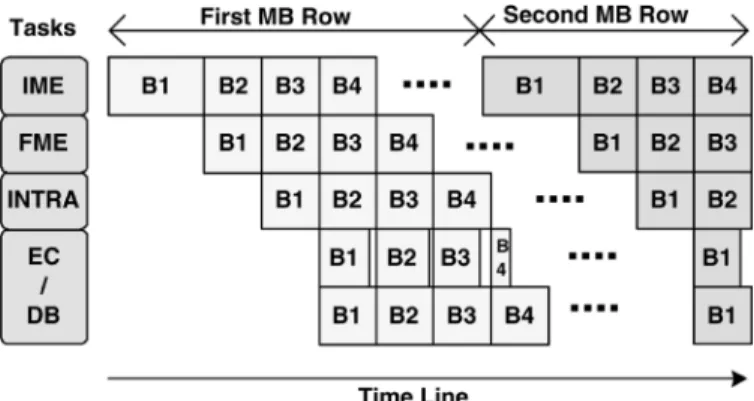
Fig. 3. MB schedule of four-stage MB pipelining.
functions extracted from the coding process are mapped into the four-stage MB pipelined structure. The processing cycles of the four stages are balanced with different degrees of par-allelism to achieve high utilization. MBs within one frame are coded in raster order with the schedule shown in Fig. 3. One horizontal column indicates the MBs with different tasks that are processed in parallel.
As for the reduction in system bandwidth, many on-chip memories are used for three purposes. First, in order to find the best matched candidate, a huge amount of reference data are required for both IME and FME. Since pixels in neigh-boring candidate blocks are considerably overlapped, and so are the search windows (SWs) of neighboring current MBs, the bandwidth of the system bus can be greatly reduced by designing local buffers to store reusable data. Second, rather than transmitted through the system bus, the raw data such as luma motion compensated MBs, transformed and quantized residues, and reconstructed MBs are shifted forward via shared memories. Third, because of data dependency, a MB is pro-cessed according to the data of the upper and the left MBs. The local memories are used to store the related data during the encoding process. For the software implementation, the external bandwidth requirement is up to 5570 GBytes/s. As for the hardware solution with the local search window memories
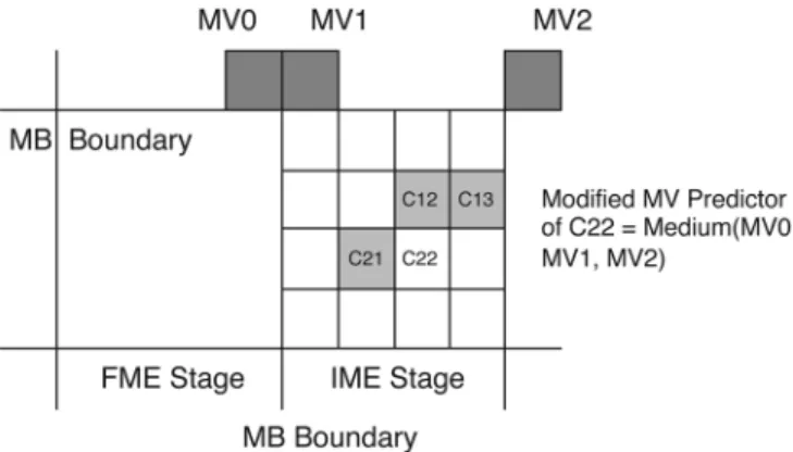
Fig. 4. Modified MVPs. In order to facilitate the parallel processing and the MB pipelining, the MVPs of all 41 blocks are changed to the medium of MV0, MV1, and MV2.
embedded, the external bandwidth requirement is reduced to 700 MBytes/s. After all three techniques are applied, the final external bandwidth requirement is about 280 MBytes/s.
B. Low-Bandwidth Parallel Integer Motion Estimation
IME requires the most computational complexity and memory bandwidth in H.264/AVC. A large degree of paral-lelism is required for SDTV/HDTV specifications. However, the sequential Lagrangian mode decision flow make it impos-sible to design the parallel architecture for IME. Therefore, techniques on algorithmic and architectural levels are used to enable parallel processing and to reduce the required hardware resources. In addition, efficient memory hierarchy and data reuse schemes are jointly applied to greatly reduce the memory bandwidth requirement.
1) Hardware-Oriented Algorithm: The MV of each block
is generally predicted by the medium values of MVs from the left, top, and top right neighboring blocks. The rate term of the Lagrangian cost function can be computed only after the MVs of the neighboring blocks are determined, which causes an in-evitable sequential processing. That is, blocks and subblocks in a MB cannot be processed in parallel. Moreover, when a MB is processed at the IME stage, its previous MB is still in the FME stage. The MB mode and the best MVs of the left blocks cannot be obtained in the four-stage MB pipelined architecture. To solve these problems, the modified MVP is applied for all 41 blocks in the MB, as shown in Fig. 4. The exact MVPs of vari-able blocks, which are the medium of MVs of the top-left, top, and top-right blocks, are changed to the medium of MVs of the top-left, top, and top-right MBs. For example, the exact MVP of the C22 4 4-block is the medium of the MVs of C12, C13, and C21. We change the MVPs of all 41 blocks to the medium of MV0, MV1, and MV2 in order to facilitate the parallel pro-cessing and the MB pipelining.
As for the searching algorithm, FS is adopted to guarantee the highest compression performance. The regular searching pattern is suitable for parallel processing. In addition, FS can effectively support VBS-ME by reusing 4 4-block SADs for larger blocks. Pixel truncation [27] of 5-bit precision and sub-sampling [28] of half pixel rate are applied to reduce the hard-ware cost. Moreover, adaptive search range adjustment [29]
is also applied to save the computations. These modifications combined with the FS pattern will not cause any noticeable quality loss for SDTV/HDTV videos, which will be shown in Section IV.
2) Architectures Design of IME: Fig. 5 shows the
low-band-width parallel IME architecture, which mainly comprises eight
PE-Array SAD Trees. The current MB (CMB) is stored in Cur. MB Reg. The reference pixels are read from external memory
and stored in Luma Ref. Pels SRAMs. Each PE array and its cor-responding 2-D SAD tree compute the 41 SADs of VBS for one searching candidate at each cycle. Therefore, eight horizontally adjacent candidates are processed in parallel. All SAD results of VBS are input to the Comparator Tree Array. Each comparator tree finds the smallest SAD among the eight search points and updates the best MV for a certain block-size.
Because SWs of neighboring current MBs are considerably overlapped, and so are the pixels of neighboring candidate blocks, a three-level memory hierarchy, including external memory, Luma Ref. Pels SRAMs, and Ref. Pels Reg. Array, is used to reduce bandwidth requirement by data reuse (DR). Three kinds of DR are implemented—MB-level DR, inter-can-didate DR, and intra-caninter-can-didate DR. The Luma Ref. Pels SRAMs are firstly embedded to achieve MB-level DR. When ME process is changed from one CMB to another CMB, there is the overlapped area between neighboring SWs. Therefore, the reference pixels of the overlapped area can be reused, and only a part of SW must be loaded from system memory. The system bandwidth can thus be reduced [30]. The Ref. Pels
Reg. Array acts as the temporal buffer between PE-Array 2-D SAD Tree and Luma Ref. Pels SRAMs. It is designed to achieve
inter-candidate DR. Fig. 6 shows the M-parallel PE-array
SAD Tree architecture. A horizontal row of reference pixels,
which are read from SRAMs, is stored and shifted downward in Ref. Pels Reg. Array. When one candidate is processed, 256 reference pixels are required. When eight horizontally adjacent candidates are processed in parallel, not (256 8) but (256 16 7) reference pixels are required. In addition, when the ME process is changed to the next eight candidates, most data can be reused in Ref. Pels Array. The proposed parallel architecture achieves inter-candidate DR in both horizontal and vertical directions and reduce the on-chip SRAM bandwidth.
Fig. 7 shows the architecture of PE-Array SAD Tree. The costs of sixteen 4 4-blocks are separately summed up by six-teen 2-D Adder Sub-trees, and then reused by one VBS Tree for larger blocks. This is so-called intra-candidate DR. All 41 SADs for one candidate are simultaneously generated and compared with the 41 best costs. No intermediate data are buffered. There-fore, this architecture can support VBS without any partial SAD registers.
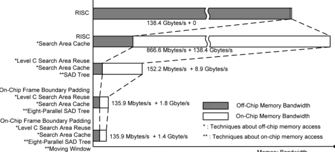
Fig. 8 summarizes the bandwidth reduction techniques of our IME design with SDTV specification and four reference frames. Five cases are discussed. The first case is only one RISC in the hardware without any local memory. The reference pixels are input directly from external memories and no on-chip memory bandwidth is required. The second case is one RISC with Luma
Ref. Pels SRAMs. By MB-level DR use of the on-chip memories,
866.6 MBytes/s of the system bandwidth is required, but the on-chip memory bandwidth is increased to 138.4 GBytes/s. This
Fig. 5. Block diagram of the low-bandwidth parallel IME engine. It mainly comprises eight PE-Array SAD Tree, and eight horizontally adjacent candidates are processed in parallel.
Fig. 6. M-parallel PE-array SAD Tree architecture. The inter-candidate DR can be achieved in both horizontal and vertical directions with Ref. Pels Reg. Array, and the on-chip SRAM bandwidth is reduced.
tradeoff is worthwhile because the system bandwidth is limited. The third case is one PE Array SAD Tree with the MB-level DR. The system bandwidth can be reduced to 152.2 MBytes/s. Be-cause of the intra-candidate DR, the on-chip memory bandwidth is only 8.9 GBytes/s. In the fourth case, the system bandwidth is reduced by on-chip frame boundary padding and inter-candidate DR. The on-chip memory bandwidth is reduced to 1.8 GBytes/s. Finally, the modified algorithm of moving window is applied in the fifth case, and the on-chip memory bandwidth is reduced to 1.4 GBytes/s. 99.90% system bandwidth is reduced compared to the first case. Furthermore, 98.99% on-chip memory band-width is saved with the proposed parallel hardware compared to the second case.
C. Parallel Fractional Motion Estimation With Lagrangian Mode Decision
The main challenge for FME hardware design is to achieve parallel processing under the constraints of sequential FME pro-cedure. In this section, we will propose a new VLSI architecture for FME in H.264/AVC. We use seven processing loops to rep-resent the FME procedure, and two decomposing techniques are proposed to parallelize the algorithm. With these techniques, the hardware architecture is designed with regular schedule, fully pipelined structure, and high utilization [31].
1) Analysis of FME Loops: For simplification, we
Fig. 7. PE-array SAD Tree architecture. The costs of sixteen 42 4-blocks are separately summed up by sixteen 2-D Adder Sub-trees and then reused by one VBS
Tree for larger blocks.
Fig. 8. Bandwidth reduction techniques in the IME engine. 99.90% system bandwidth are reduced with the search area cache memories and the MB–level DR. 99.22% on-chip memory bandwidth is saved with the proposed parallel hardware.
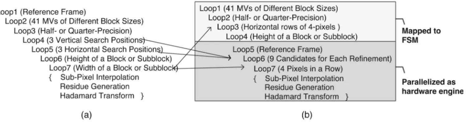
shown in Fig. 9(a). The first two loops are for the multiple refer-ence frames and the 41 variable blocks, respectively. The third loop is the refinement procedure of half-pixel precision and then quarter-pixel precision. The next two loops are for the 3 3 candidates of each refinement process. The last two loops are iterations of pixels in one candidate, and the number of itera-tion ranges from 16 16 to 4 4. Main tasks inside the most inner loop are the fractional pixel interpolation, residue genera-tion, and Hadamard transform. The residue generation performs the subtraction operation between current pixels and reference pixels. The interpolation requires a 6-tap FIR filter in both hor-izontal and vertical directions. The Hadamard transform is a 2-D 4 4 matrix operation. These three main tasks have
dif-ferent input/output throughput rates, which is very challenging to achieve parallel processing and high utilization at the same time.
In order to meet the real-time constraint, some loops must be unrolled and mapped into hardware for parallel processing. The costs of a certain block in different reference frames are pro-cessed independently. Therefore, the first loop has no sequential issues and can be easily unrolled for parallel processing. The second loop is not suitable to be unrolled because 41 MVs of VBS-ME may point to different positions. The memory bitwidth of SW will become too large if the reference pixels of VBS-ME are read in parallel. In addition, there is inevitable sequential processing order among VBS-ME for taking MV
Fig. 9. (a) Original FME procedure. (b) Rearranged FME procedure. FME is efficiently mapped to parallel hardware with 42 4-block decomposition and efficient scheduling for vertical DR.
Fig. 10. Main concepts of FME design. (a) 42 4-block decomposition. (b) Ef-ficient scheduling for vertical DR.
costs into consideration. The third loop cannot be parallelized since the searching center of quarter-resolution refinement depends on the result of half-resolution refinement. Similar to the first loop, the costs of 3 3 candidates are processed independently and are feasible for parallel processing. Most interpolated pixels can be reused by the neighboring candidates to save redundant computations and processing cycles. The iteration count of the last two loops depends on the block size, which ranges from 4 to 16. The parallelization strategy will affect the hardware utilization for supporting both 16 16 and 4 4 blocks. In addition, the 6-tap 2-D FIR filter and 4 4 Hadamard transform must also be taken into consideration.
Two techniques here are proposed with hardware consid-erations. The first technique is 4 4-block decomposition. The 4 4 block is the smallest common element of blocks with different sizes, and the sum of absolute transformed differences (SATD) is also based on 4 4 blocks. That is, every block and subblock in a MB can be decomposed into several 4 4-elements with the same MV. Therefore, we can concentrate on designing a 4 4-element processing unit (PU) and then apply the folding technique to reuse the 4 4-element PU for different block sizes. Fig. 10(a) takes the 16 8 block as an example. One 16 8 block is decomposed into eight 4 4 element blocks. These 4 4 element blocks are processed in sequential order, and the corresponding SATDs are then accumulated for the final costs. The second technique is efficient scheduling for vertical DR. After the 4 4-block
decomposition, redundant interpolating operations appear in the overlapped area of adjacent interpolation windows, which is shown in Fig. 10(a). As Fig. 10(b) shows, the interpolation windows of vertically adjacent 4 4-elements are integrated. Both the hardware utilization and the throughput are increased. Please note that each 4 4-element PU is arranged with four degrees of parallelism to process four horizontally adjacent pixels for residue generation and Hadamard transform in par-allel. Most horizontally adjacent integer pixels can be reused for the horizontal FIR filters, and the on-chip memory bandwidth can be further reduced.
2) Architectures Design of FME: Fig. 11 shows the
par-allel FME architecture. The IME generates 41 4 of IMVs. The FME then refines these MVs to quarter-pel resolution, and MC is performed after inter mode decision. The outputs include the best prediction mode, the corresponding MVs, and the MC re-sults. The Luma Ref. Pels SRAMs storing the reference pixels are shared with IME pipeline stage to reduce the system band-width. There are nine 4 4-block PUs to process nine candi-dates around the refinement center. Each 4 4-block PU is re-sponsible for the residue generation and Hadamard transform of each candidate. The 2-D Interpolation Engine generating refer-ence pixels in half-pel or quarter-pel resolution is shared by all nine 4 4-block PUs to achieve the DR and the local bandwidth reduction. The Rate-Distortion Optimized Mode Decision is re-sponsible for the sequential procedures of the first through the fourth loops in Fig. 9(b).
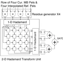
The architecture of each 4 4-block PU is shown in Fig. 12. Four subtractors generate four residues in parallel and transmit them to the 2-D Hadamard Transform Unit. The 2-D Hadamard
Transform Unit [32] contains two 1-D Hadamard units and
transpose shift registers. The first 1-D Hadamard unit filters the residues row by row in each 4 4 block, while the second
1-D Hadamard unit processes column by column. The data
flow of the transpose registers can be configured as rightward shift or downward shift. Two configurations interchange with each other every four cycles. First, the rows of 1-D transformed residues of the first 4 4 block are written into the transpose registers horizontally. After four cycles, the columns of the 1-D transformed residues are read vertically for the second 1-D Hadamard transform. Meanwhile, the rows of 1-D transformed residues of the second 4 4 block are written into transpose registers vertically. In this way, the 2-D Hadamard Transform
Fig. 11. Block diagram of the FME engine. There are nine 424-block PUs to process nine candidates around the refinement center. One 2-D Interpolation Engine is shared by nine 42 4-block PUs to achieve DR and local bandwidth reduction.
Fig. 12. Block diagram of 42 4-block PU. The 2-D Hadamard Transform Unit is fully pipelined with Residue Generators.
Unit is fully pipelined with residue generators. The latency of
the 2-D Hadamard Transform Unit is four cycles, and there is no bubble cycle.
Fig. 13(b) shows the 2-D Interpolation Engine. The opera-tions of the 2-D FIR filter are also decomposed to two 1-D FIR filters with the shift buffers located in V-IP Units. A row of ten horizontally adjacent integer pixels are fed into the five 6-tap horizontal FIR filters (HFIRs) for interpolating five horizontal pixels in half-pel resolution. These five half pixels and six neigh-boring integer pixels are then shifted downward in the V-IP
Unit, as shown in Fig. 13(a). After the six cycles latency, the
11 VFIRs in the V-IP Units generate vertical pixels in half-pel resolution by filtering the corresponding columns of pixels in
V-IP Units. The dotted rectangle in the bottom of Fig. 13(b)
stands for all predictors needed each cycles for residue genera-tion in half pixel refinement. As for quarter refinement, another bilinear filtering engine getting data from the dotted rectangle is responsible for quarter-pixels generation. The efficient vertical scheduling can reuse interpolated pixels in the V-IP Units, and 26% of cycles can be saved.
D. Reconfigurable Intra Predictor Generator
The intra prediction supports various prediction modes, which includes four I16 MB modes, night I4 MB modes, and four Chorma intra modes. If a RISC-based solution is adopted, where the prediction values are generated sequentially for each mode, the required operation frequency will become too high. On the other hand, if the dedicated hardware is adopted, 17 kinds of PEs for the 17 modes lead to high hardware cost. Therefore, the reconfigurable circuit with the resource sharing for all intra prediction modes is an efficient solution [25].
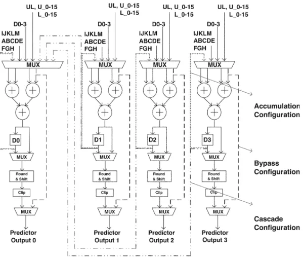
The hardware architecture of the four-parallel reconfigurable intra predictor generator is shown in Fig. 14. Capital letters (A, B, C, ) are the neighboring 4 4-block pixels. UL, L0–L15, and U0–U15 denote the bottom right pixel from the upper left MB, the 16 pixels of the right most column from the left MB, and the 16 pixels of the bottom row from the upper MB, re-spectively. Four different configurations are designed to sup-port all intra prediction modes in H.264/AVC. First, the I4 MB/ I16 MB horizontal/vertical modes use the bypass data path to se-lect the predictors extended from the block boundaries. Second, multiple PEs are cascaded to sum up the DC value for I4 MB/ I16 MB/chroma DC mode. Third, the normal configuration is
Fig. 13. (a) Block diagram of V-IP Unit. (b) Block diagram of 2-D Interpolation Engine. The operations of 2-D FIR are decomposed to two 1-D FIRs with an interpolation shift buffer. The efficient vertical scheduling can reuse interpolated pixels in the V-IP Units, and 26% of cycles can be saved.
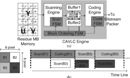
Fig. 15. (a) Dual-buffer architecture of CAVLC engine. (b) Block-pipelined schedule. by switching the ping-pong mode buffers, scanning and coding of the 42 4-blocks can be processed simultaneously, and the throughput and the hardware utilization are doubled.
used for I4 MB directional modes 3–8. The four PEs select the corresponding pixels multiple times according to the weighted factors and generate four predictors independently. Finally, the recursive configuration is designed for I16 MB plan prediction. The predictors are generated by adding the gradient values to the result of the previous cycles.
E. Dual-Buffer CAVLC Architecture With Block Pipelining
The symbols of the 4 4-blocks are coded by CAVLC through two phases, a scanning phase and a coding phase. In the scanning phase, the residues are read from the Residue MB
SRAM in the backward zig-zag order. The run-level symbols
and required information are extracted. In the coding phase, the symbols are translated into codewords with the corresponding class of tables. Different from the traditional fixed VLC ta-bles, CAVLC utilizes the inter-symbol correlation to further reduce the statistical redundancy. This means the selection of VLC tables depends on the related statistics such as the total coefficient number and the total run number. Not until the scanning of a 4 4-block is finished can we know the statistic information. The scanning and coding phases of each block must be processed in the sequential order, which leads to low hardware utilization.
Fig. 15(a) shows the proposed dual-buffer architecture and the corresponding block pipelined scheme [33]. There is a pair of ping-pong mode statistic buffers. After the scanning phase of the first 4 4-block, the run-level symbols and related statistic information are stored in the first buffer, and the coding phase starts. At the same time, the scanning phase of the second 4 4-block is processed in parallel by use of the second buffer. As shown in Fig. 15(b), by switching the ping-pong mode buffers, scanning and coding of the 4 4-blocks within a MB can be processed simultaneously with the interleaved manner. In this way, both the throughput and the hardware utilization are doubled.
To further improve our design, a zero skipping technique is applied. When the residues within an 8 8-block are all zeros, the 4 4-blocks inside are unnecessary to be coded. In this sit-uation, the scanning process can be early skipped. The symbol
of Code Block Pattern (CBP) in the MB header is used for the skipping decision.
F. Deblocking Filter
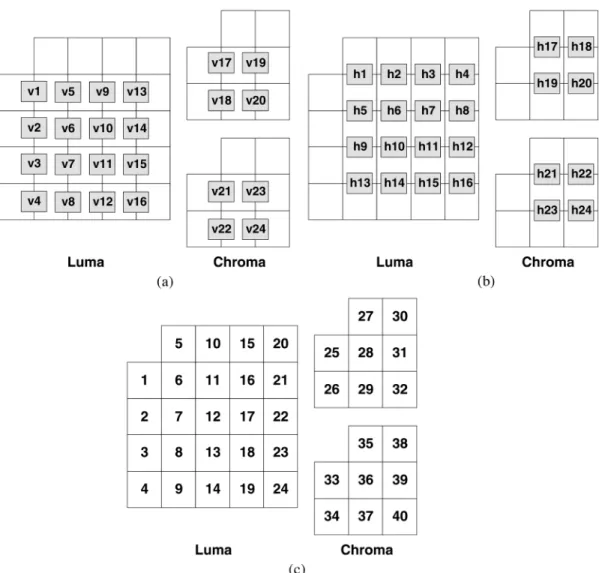
The deblocking filter is employed in-loop at 4 4 block boundaries to reduce block artifacts in H.264/AVC. In the reference software, the processing order of block boundaries is done vertically and then horizontally in the order as shown in Fig. 16 (v1, v2, v3, , v23, v24, and then h1, h2, h3, , h23, h24). Fig. 17 shows the proposed hardware architecture. Before deblocking a MB, the MB data and adjacent block data are prepared in the Deblock SRAM. An Eight-parallel 1-D
Filter can process eight pixel for one edge in parallel. The 8 4 unfiltered pixels of two adjacent 4 4-blocks are stored in the
8 4-Pixel Array with reconfigurable data paths in order to
support both horizontal and vertical filtering with the same 1-D filters.
The main innovation is described as follows. The processing order of both vertical and horizontal boundaries is modified to the transpose order (v1, v5, v9, , v22, v24 and then h1, h5, h9, , h22, h24, as shown Fig. 16) [34]. This modification can achieve a considerable DR without affecting the data depen-dency defined by H.264/AVC standard. As shown in Fig. 16, after the boundary V1 is horizontally filtered, we only have to write block 1 from the array to the Deblock SRAM. As for block 6, we can directly send it back to the filter with block 11 from SRAM to process the boundary V5. This data reuse scheme can be applied by both horizontal and vertical filters. About 50% bandwidth of Deblock SRAM can be reduced, and the hardware utilization and throughput are increased.
IV. EXPERIMENTALRESULTS
A. Implementation Results of H.264/AVC SDTV/HDTV720p Encoder
The specification of the proposed H.264/AVC encoder is baseline profile with level up to 3.1. The maximum compu-tational capability is to real-time encode SDTV 30 fps video with four reference frames or HDTV720p 30 fps video with
Fig. 16. Processing order of the boundaries of 424 blocks. (a) Horizontal filtering across vertical edges. (b) Vertical filtering across horizontal edges. (c) Block index.
Fig. 17. Block diagram of the DB engine.
one reference frame. Table II shows the logic gate count profile synthesized at 120 MHz. The total logic gate count
is about 922.8 K. The prediction engines, including IME, FME, and IP stages, dominate 90% logic area. As for on-chip
TABLE II
HARDWARECOST OFH.264/AVC ENCODER
Fig. 18. Die micrograph of the H.264/AVC encoder [35].
TABLE III
SPECIFICATION OF THEDEVELOPEDH.264/AVC BASELINE
PROFILEENCODERCHIP
SRAM, 34.88 KB are required. The chip is fabricated with UMC 0.18- m 1P6M CMOS process. Fig. 18 shows the die micrograph. The core size is 7.68 4.13 mm . The power consumption is 581 mW for SDTV videos and 785 mW for HDTV720p videos at 1.8-V supply voltage with 81/108 MHz operating frequency. The detailed chip features are shown in Table III.
The encoded video quality of our chip is competitive with that of reference software, in which FS is implemented with La-grangian mode decision. As shown in Fig. 19, with improvement of the Lagrangian multipliers, our compression performance is even better at high bitrate.
B. Comparison
1) Low Bandwidth Parallel IME: Table IV shows the
comparison between the different IME architectures. All these works target at H.264/AVC and support VBS-ME with FS pattern. Among them, the proposed architecture can support the highest specification with largest SR and MRF number. In
TABLE IV
COMPARISON OF THEH.264/AVC IME ARCHITECTURES
TABLE V
COMPARISONBETWEEN THEPROPOSEDARCHITECTURE AND THENEWESTONES
order to compare the architectures with different specifications, one criterion of Gate Count Per PE (GCPP), which is defined as (Gate Count)/(# of PE), is used to judge the hardware ef-ficiency. Note that, since the number of PE is proportional to the number of degree of parallelism, GCPP can represent the normalized hardware cost for unit degree of parallelism. The higher of GCPP indicates poorer hardware resource sharing caused by poorer data reuse. The PE Array Adder Tree ar-chitecture can support intra-candidate DR of VBS without partial SAD registers. In addition, for inter-candidate DR, most hardware resources of Ref. Pels Reg. Array can be shared by the multiple PE Array Adder Trees. Therefore, our architecture has the lowest GCPP factor and is much more suitable for systems with high specifications.
2) Dual-Buffer Block-Pipelined CAVLC Engine: Fig. 20
shows the number of processing cycles required by the single-buffer architecture [25], the proposed dual-single-buffer block-pipelined architecture, and the proposed one with the zero skipping technique. Compared with the single-buffer archi-tecture, the dual-buffer block-pipelined architecture processes two 4 4-blocks in parallel and thus enhances the hardware utilization and throughput. It can reduce up to half of the processing cycles at high bitrate situations. At low bitrate situations, most residues are zero, and the scanning phase dominates the processing cycles. The zero skipping technique can further improve the design by eliminating the redundant scanning process and up to 90% of the cycles are reduced.
3) DB Filter: Our DB filter design is the first hardware
so-lution for H.264/AVC in [34]. Table V shows the comparison between the proposed architecture and the newest ones. Based on our architecture, the column addressing for pixels in MB is used after horizontal filtering to favor the direction of vertical filtering [37]. The horizontal and vertical edges are filtered in interleaving manner, and more DR can be achieved [38]. The performance of our architecture is quit enough for HDTV720p 30 fps at 100-MHz operation frequency. The improved ones can be used for higher specifications or low power considerations.
Fig. 19. Comparison of coding quality with the reference software [14].
Fig. 20. Numbers of processing cycles per MB required by the single buffer architecture [25], the proposed dual-buffer architecture, and the proposed one with zero skipping technique. (a) Foreman, QCIF 30 fps. (b) Mobile Calendar, QCIF 30 fps.
TABLE VI
COMPARISONBETWEEN THEPROPOSEDH.264/AVC ENCODER ANDSOMEHARDWIREDH.264/AVC CODECS[39]
4) H.264/AVC SDTV/HDTV720p Encoder: Table VI shows
the comparison between the proposed H.264/AVC encoder and some hardwired H.264/AVC codecs [39]. Our encoder is the first published single-chip H.264/AVC encoder [35], and can support real-time encoding HDTV720p videos in H.264/AVC. All compression tools in baseline profile, including VBS-ME, MRF-ME, quarter-pel resolution, intra prediction, and CAVLC, are supported. The Lagrangian mode decision flow modified from reference software [14] is implemented. Therefore, our
design can achieve the high compression performance. Among these works, the proposed design can support the highest speci-fication, and has smaller gate count compared to [40] and [41].
V. CONCLUSION
In this paper, an H.264/AVC baseline profile single-chip encoder with the silicon core size of 7.68 4.13 mm and 0.18- m CMOS technology is presented. A four-stage mac-roblock (MB) pipelined architecture can encode HDTV720p 30
fps videos in real time at 108 MHz. The new pipelined archi-tecture doubles the throughput of the conventional two-stage MB pipelined architecture with high hardware utilization for H.264/AVC. The encoder contains five engines of integer motion estimation (IME), fractional motion estimation (FME), intra prediction with reconstruction loops (IP), entropy coding (EC), and in-loop deblocking filter (DB). For IME, a parallel array of eight SAD trees is designed with three-level memory hierarchy and data reuse (DR). For FME, a loop decomposition method is provided to obtain an efficient mapping from the algorithm to the architecture with a regular flow. For IP, the reconfigurable intra predictor generators are adopted. For EC, a dual-buffer block-pipelined CAVLC module can double the throughput and utilization. For DB, an advanced filtering sched-uling is proposed to reduce 50% on-chip memory bandwidth. In summary, parallel processing and pipelining techniques are used to reduce the frequency and increase the utilization, while folding and reconfigurable techniques are applied to reduce the area. With these techniques, the first single-chip H.264/AVC encoder is efficiently implemented with full search quality for HDTV applications.
REFERENCES
[1] Draft ITU-T Recommendation and Final Draft International Standard
of Joint Video Specification, Joint Video Team, ITU-T
Recommenda-tion H.264 and ISO/IEC 14496-10 AVC, May 2003.
[2] Information Technology—Coding of Audio-Visual Objects—Part 2:
Vi-sual, ISO/IEC 14496-2, 1999.
[3] Video Coding for Low Bit Rate Communication, ITU-T Recommenda-tion H.263, Feb. 1998.
[4] Information Technology—Generic Coding of Moving Pictures and
As-sociated Audio Information: Video, ISO/IEC 13818-2 and ITU-T Rec.
H.262, 1996.
[5] A. Joch, F. Kossentini, H. Schwarz, T. Wiegand, and G. J. Sullivan, “Performance comparison of video coding standards using Lagragian coder control,” in Proc. IEEE Int. Conf. Image Processing (ICIP’02), 2002, pp. 501–504.
[6] T. Wedi and H. G. Musmann, “Motion- and aliasing-compensated prediction for hybrid video coding,” IEEE Trans. Circuits Syst. Video
Technol., vol. 13, no. 7, pp. 577–586, Jul. 2003.
[7] T. Wiegand and B. Girod, Multi-Frame Motion-Compensated
Predic-tion for Video Transmission. Boston, MA: Kluwer Academic, 2002. [8] T. Wiegand, X. Zhang, and B. Girod, “Long-term memory motion-compensated prediction,” IEEE Trans. Circuits Syst. Video Technol., vol. 9, no. 1, pp. 70–84, Feb. 1999.
[9] D. Marpe, H. Schwarz, and T. Wiegand, “Context-based adaptive bi-nary arithmetic coding in the H.264/AVC video compression standard,”
IEEE Trans. Circuits Syst. Video Technol., vol. 13, no. 7, pp. 620–636,
Jul. 2003.
[10] P. List, A. Joch, J. Lainema, G. Bjøntegaard, and M. Karczewicz, “Adaptive deblocking filter,” IEEE Trans. Circuits Syst. Video Technol., vol. 13, no. 7, pp. 614–619, Jul. 2003.
[11] T. Wiegand, G. J. Sullivan, G. Bjøntegaard, and A. Luthra, “Overview of the H.264/AVC video coding standard,” IEEE Trans. Circuits Syst.
Video Technol., vol. 13, no. 7, pp. 560–576, Jul. 2003.
[12] J. Ostermann, J. Bormans, P. List, D. Marpe, M. Narroschke, F. Pereira, T. Stockhammer, and T. Wedi, “Video coding with H.264/AVC; tools, performance, and complexity,” IEEE Circuits Syst. Mag., vol. 4, no. 1, pp. 7–28, 1Q, 2004.
[13] A. Puri, X. Chen, and A. Luthra, “Video coding using the H.264/MPEG-4 AVC compression standard,” in Signal Process.:
Image Commun., Oct. 2004, vol. 19, no. 9, pp. 793–849.
[14] Joint Video Team Reference Software JM7.3, ITU-T, Aug. 2003 [On-line]. Available: http://bs.hhi.de/suehring/tml/download/
[15] Iprof ftp server. [Online]. Available: http://iphome.hhi.de/suehring/ tml/download
[16] H.-C. Chang, L.-G. Chen, M.-Y. Hsu, and Y.-C. Chang, “Performance analysis and architecture evaluation of MPEG-4 video codec system,” in Proc. IEEE Int. Symp. Circuits and Systems (ISCAS’00), May 2000, vol. 2, pp. 449–452.
[17] M. Takahashi, T. Nishikawa, M. Hamada, T. Takayanagi, H. Arakida, N. Machida, H. Yamamoto, T. Fujiyoshi, Y. Ohashi, O. Yamagishi, T. Samata, A. Asano, T. Terazawa, K. Ohmori, Y. Watanabe, H. Naka-mura, S. Minami, T. Kuroda, and T. Furuyama, “A 60-MHz 240-mW MPEG-4 videophone LSI with 16-Mb embedded DRAM,” IEEE J.
Solid-State Circuits, vol. 35, no. 11, pp. 1713–1721, Nov. 2000.
[18] H. Nakayama, T. Yoshitake, H. Komazaki, Y. Watanabe, H. Araki, K. Morioka, J. Li, L. Peilin, S. Lee, H. Kubosawa, and Y. Otobe, “A MPEG-4 video LSI with an error-resilient codec core based on a fast motion estimation algorithm,” in IEEE Int. Solid-State Circuits Conf.
(ISSCC) Dig. Tech. Papers, Feb. 2002, vol. 1, pp. 368–474.
[19] Y.-W. Huang, T.-C. Wang, B.-Y. Hsieh, and L.-G. Chen, “Hardware ar-chitecture design for variable block size motion estimation in MPEG-4 AVC/JVT/ITU-T H.264,” in Proc. IEEE Int. Symp. Circuits and
Sys-tems (ISCAS’03), 2003, pp. 796–799.
[20] J.-H. Lee and N.-S. Lee, “Variable block size motion estimation algo-rithm and its hardware architecture for H.264,” in Proc. IEEE Int. Symp.
Circuits and Systems (ISCAS’04), May 2004, vol. 3, pp. 740–743.
[21] S. Y. Yap and J. V. McCanny, “A VLSI architecture for variable block size video motion estimation,” IEEE Trans. Circuits Syst. II, Expr.
Briefs, vol. 51, no. 7, pp. 384–389, Jul. 2004.
[22] M. Kim, I. Hwang, and S.-I. Chae, “A fast vlsi architecture for full-search variable block size motion estimation in MPEG-4 AVC/H.264,” in Proc. Asia and South Pacific Design Automation Conf., Jan. 2005, vol. 1, pp. 631–634.
[23] W.-M. Chao, T.-C. Chen, Y.-C. Chang, C.-W. Hsu, and L.-G. Chen, “Computationally controllable integer, half, and quarter-pel motion estimator for MPEG-4 advanced simple profile,” in Proc. 2004 Int.
Symp. Circuits and Systems (ISCAS’03), May 2003, vol. 2, pp.
II788–II791.
[24] M. Miyama, J. Miyakoshi, Y. Kuroda, K. Imamura, H. Hashimoto, and M. Yoshimoto, “A sub-mW MPEG-4 motion estimation processor core for mobile video application,” IEEE J. Solid-State Circuits, vol. 39, no. 9, pp. 1562–1570, Sep. 2004.
[25] Y.-W. Huang, B.-Y. Hsieh, T.-C. Chen, and L.-G. Chen, “Analysis, fast algorithm, and VLSI architecture design for H.264/AVC intra frame coder,” IEEE Trans. Circuits Syst. Video Technol., vol. 15, no. 3, pp. 378–401, Mar. 2005.
[26] T.-C. Chen, Y.-W. Huang, and L.-G. Chen, “Analysis and design of macroblock pipelining for H.264/AVC VLSI architecture,” in Proc. Int.
Symp. Circuits and Systems (ISCAS’04), 2004, pp. II273–II276.
[27] Z.-L. He, C.-Y. Tsui, K.-K. Chan, and M.-L. Liou, “Low-power VLSI design for motion estimation using adaptive pixel truncation,” IEEE
Trans. Circuits Syst. Video Technol., vol. 10, no. 5, pp. 669–678, Aug.
2000.
[28] B. Liu and A. Zaccarin, “New fast algorithms for the estimation of block motion vectors,” IEEE Trans. Circuits Syst. Video Technol., vol. 3, no. 2, pp. 148–157, Apr. 1993.
[29] S. Saponara and L. Fanucci, “Data-adaptive motion estimation algo-rithm and VLSI architecture design for low-power video systems,”
Proc. IEE Computers and Digital Techniques, vol. 151, no. 1, pp.
51–59, 2004.
[30] J.-C. Tuan, T.-S. Chang, and C.-W. Jen, “On the data reuse and memory bandwidth analysis for full-search block-matching VLSI architecture,”
IEEE Trans. Circuits Syst. Video Technol., vol. 12, no. 1, pp. 61–72,
Jan. 2002.
[31] T.-C. Chen, Y.-W. Huang, and L.-G. Chen, “Fully utilized and reusable architecture for fractional motion estimation of H.264/AVC,” in Proc. IEEE Int. Conf. Acoustics, Speech, and Signal Processing
(ICASSP’04), 2004, pp. V9–V12.
[32] T.-C. Wang, Y.-W. Huang, H.-C. Fang, and L.-G. Chen, “Parallel 4x4 2D transform and inverse transform architecture for MPEG-4 AVC/H. 264,” in Proc. IEEE Int. Symp. Circuits and Systems (ISCAS ’03), 2003, pp. 800–803.
[33] T.-C. Chen, Y.-W. Huang, C. Y. Tsai, and L.-G. Chen, “Dual-block-pipelined VLSI architecture of entropy coding for H.264/AVC baseline profile,” in IEEE VLSI-TSA Int. Symp. VLSI Design, Automation and
Test (VLSI-TSA-DAT’05), 2005, pp. 271–1274.
[34] Y.-W. Huang, T.-W. Chen, B.-Y. Hsieh, T.-C. Wang, T.-H. Chang, and L.-G. Chen, “Architecture design for deblocking filter in H.264/ JVT/AVC,” in Proc. IEEE Int. Conf. Multimedia and Expo (ICME’03), 2003, pp. 1693–1696.
[35] Y.-W. Huang, T.-C. Chen, C.-H. Tsai, C.-Y. Chen, T.-W. Chen, C.-S. Chen, C.-F. Shen, S.-Y. Ma, T.-C. Wang, B.-Y. Hsieh, H.-C. Fang, and L.-G. Chen, “A 1.3TOPS H.264/AVC single-chip encoder for HDTV applications,” in IEEE Int. Solid-State Circuits Conf. (ISSCC)
[40] The Renesas Technology Website. [Online]. Available: http://www.re-nesas.com
[41] The Fujitsu Website. [Online]. Available: http://www.fujitsu.com [42] The Techno Mathematical Website. [Online]. Available: http://www.
tmath.co.jp
Tung-Chien Chen was born in Taipei, Taiwan, R.O.C., in 1979. He received the B.S. degree in electrical engineering and the M.S. degree in elec-tronic engineering from National Taiwan University, Taipei, in 2002 and 2004, respectively, where he is working toward the Ph.D. degree in electronics engineering.
His major research interests include motion estimation, algorithm and architecture design of MPEG-4 and H.264/AVC video coding, and low-power video coding architectures.
Shao-Yi Chien was born in Taipei, Taiwan, R.O.C., in 1977. He received the B.S. and Ph.D. degrees from the Department of Electrical Engineering, National Taiwan University, Taipei, in 1999 and 2003, respectively.
During 2003 to 2004, he was a research staff member with Quanta Research Institute, Tao Yuan Shien, Taiwan. In 2004, he joined the Graduate Institute of Electronics Engineering and Department of Electrical Engineering, National Taiwan Univer-sity, as an Assistant Professor. His research interests include video segmentation algorithm, intelligent video coding technology, image processing, computer graphics, and associated VLSI architectures.
Yu-Wen Huang was born in Kaohsiung, Taiwan, R.O.C., in 1978. He received the B.S. degree in electrical engineering and the Ph.D. degree in the Graduate Institute of Electronics Engineering from National Taiwan University, Taipei, Taiwan, in 2000 and 2004, respectively.
He joined MediaTek, Inc., Hsinchu, Taiwan, in 2004, where he develops integrated circuits related to video coding systems. His research interests include video segmentation, moving object detection and tracking, intelligent video coding technology, motion estimation, face detection and recognition, H.264/AVC video coding, and associated VLSI architectures.
Chen-Han Tsai received the B.S.E.E. degree from National Taiwan University, Taipei, Taiwan, R.O.C., in 2002, where he is currently working toward the Ph.D. degree in the Graduate Institute of Electronics Engineering.
His major research interests include face detection and recognition, motion estimation, H.264/AVC video coding, digital TV systems, and related VLSI architectures.
To-Wei Chen was born in Taipei, Taiwan, R.O.C., in 1978. He received the B.S. degree in electrical engineering and the M.S. degree in the Graduate Institute of Electronics Engineering from National Taiwan University (NTU), Taipei, in 2000 and 2005, respectively.
He joined MediaTek, Inc., Hsinchu, Taiwan, in 2005, where he develops integrated circuits related to video coding systems. His major research interests include VLSI design and implementation for H. 264/MPEG-4 AVC codec system.
Liang-Gee Chen (S’84–M’86–SM’94–F’01) re-ceived the B.S., M.S., and Ph.D. degrees in electrical engineering from National Cheng Kung University, Tainan, Taiwan, R.O.C., in 1979, 1981, and 1986, respectively.
In 1988, he joined the Department of Electrical Engineering, National Taiwan University, Taipei, Taiwan, R.O.C. During 1993–1994, he was a Visiting Consultant in the DSP Research Department, AT&T Bell Laboratories, Murray Hill, NJ. In 1997, he was a Visiting Scholar in the Department of Electrical Engineering, University of Washington, Seattle. Currently, he is a Professor at National Taiwan University. His current research interests are DSP architecture design, video processor design, and video coding systems. He has been an Associate Editor of the Journal of Circuits, Systems, and Signal Processing since 1999 and has served as a Guest Editor for the Journal of Video Signal
Processing Systems.
Dr. Chen has served as an Associate Editor of IEEE TRANSACTIONS ON
CIRCUITS ANDSYSTEMS FORVIDEOTECHNOLOGYsince 1996, as Associate Editor of the IEEE TRANSACTIONS ON VERY-LARGE-SCALE INTEGRATION
(VLSI) SYSTEMSsince 1999, and as Associate Editor of IEEE TRANSACTIONS ONCIRCUITS ANDSYSTEMS, PARTII: EXPRESSBRIEFSsince 2000. He is also the Associate Editor of the PROCEEDINGS OF THEIEEE. He was the General Chairman of the 7th VLSI Design/CAD Symposium in 1995 and of the 1999 IEEE Workshop on Signal Processing Systems: Design and Implementation. He is a Past Chair of Taipei Chapter of IEEE Circuits and Systems (CAS) Society, and is a Member of the IEEE CAS Technical Committee of VLSI Sys-tems and Applications, the Technical Committee of Visual Signal Processing and Communications, and the IEEE Signal Processing Technical Committee of Design and Implementation of SP Systems. He is the Chair-Elect of the IEEE CAS Technical Committee on Multimedia Systems and Applications. During 2001–2002, he served as a Distinguished Lecturer of the IEEE CAS Society. He received Best Paper Awards from the R.O.C. Computer Society in 1990 and 1994. Annually from 1991 to 1999, he received Long-Term (Acer) Paper Awards. In 1992, he received the Best Paper Award of the 1992 Asia-Pacific Conference on Circuits and Systems in the VLSI design track. In 1993, he received the Annual Paper Award of the Chinese Engineers Society. In 1996 and 2000, he received the Outstanding Research Award from the National Science Council, and in 2000, the Dragon Excellence Award from Acer. He is a Member of Phi Tan Phi.