properties and microstructure relationships are discussed in terms of the lattice defects in the grains and proton discharge during electroplating.
© 2005 The Electrochemical Society. 关DOI: 10.1149/1.1901064兴 All rights reserved.
Manuscript submitted July 27, 2004; revised manuscript received November 25, 2004. Available electronically April 22, 2005.
Because electrodeposited and electroless nickel-phosphorus al-loys are extensively used as protective coatings1-4or electrodes4-11 for electrochemical catalysis, understanding nickel and phosphorus codeposition mechanism, and the microstructures as well as physio-chemical properties of the deposits, is now all the more important. For electrodeposition using phosphorus oxyacid as the source of phosphorus in the deposit, two codeposition mechanisms have been proposed: direct mechanism and indirect mechanism. Some re-searchers such as Brenner12 first and recently Morikawa et al.,13 considered the direct codeposition mechanism as Ni2+ and phos-phorus oxyacid being directly reduced to nickel and phosphos-phorus adatoms, which then combine to form NinP solid solution. For the indirect codeposition mechanism, phosphorus oxyacid is reduced to phosphine which then, in the presence of Ni2+, is oxidized to phos-phorus adatoms, while Ni2+ are simultaneously reduced to nickel.1,14-17
The microstructure of Ni-P electrodeposits has been extensively studied, in particular the crystalline to amorphous transition of the deposits as their deposit phosphorus content increases. Bredael et al.18studied the recrystallization behaviors of Ni-P electrodeposits using X-ray diffraction 共XRD兲 and transmission electron micros-copy共TEM兲, and noted the Ni-P alloy changes from crystalline to amorphous as its deposit phosphorus content exceeds 11.6 -13.1 wt %. By employing TEM, Vafaei-Makhsoos et al.19 charac-terized the alloys with 3.8 and 6.7 wt % phosphorus as a solid so-lution composed of micrometer-sized grains, and the alloys contain-ing 11.7 and 13 wt % as an amorphous matrix dispersed with micrometer-sized crystals. Studied with cross-sectional high-resolution TEM, the Ni77P23 alloy 共with 13.6 wt % phosphorus兲, which has been characterized as amorphous by XRD, is identified as an amorphous matrix dotted with nanosized crystals, as illustrated by Shimizu et al.20 The notable inconsistency about the deposit phosphorus content at which crystalline-to-amorphous transition oc-curs may be due to the different characterization methods and the various solutions employed for electrodeposition.
Ni-P electrodeposits are potentially applied as the protective coatings with good wear resistance and as the electroformed struc-tures which possess better high-temperature strength than the pure nickel electrodeposit if the internal stress of the deposits can be well controlled. Although pure nickel plated from the nickel sulfamate bath has lower internal stress than that deposited from the sulfate and chloride baths,21-23 the Ni-P electrodeposits plated from the nickel sulfamate bath is less well studied comparing to its nickel
sulfate and citrate counterparts. In this study, the Ni-P alloys with various phosphorus contents were electroplated from nickel sulfa-mate baths through the additions of distinct amounts of H3PO3. The mechanical properties of the deposits, such as hardness and internal stress, were found to correlate well to the structural evolution of the deposits as their deposit phosphorus content was increased.
Experimental
Electroplating.—Ni-P electrodeposits were plated onto copper plates. The copper plates were mechanically polished using emery paper up to grade 2400, rinsed with deionized water, and cleaned in acetone ultrasonically, and finally dried using a stream of hot air. Prior to electroplating, the plates were activated in 5% sulfuric acid at room temperature. The nickel sulfamate bath was composed of 90 g dm−3of nickel ions as nickel sulfamate, 3 g dm−3nickel chlo-ride, 40 g dm−3boric acid, and 0.4 g dm−3sodium dodecyl sulfate as a wetting agent. To electroplate the Ni-P alloys with various amounts of phosphorus, 1-40 g dm−3H
3PO3was added to the sulfa-mate bath. A 2.5 dm3solution at 50°C was used for electroplating and was continuously stirred by a stream of room-temperature air throughout the electroplating. The electroplating was performed gal-vaostatically at 8 A dm−2. The copper plates before and after elec-troplating were weighted, respectively, by an electronic balance with an accuracy of 0.1 mg. The mass of the deposit was the mass dif-ference of the copper plate with and without the deposit.
Microstructural characterization.—The composition of the de-posits was measured by electron microprobe analysis共EPMA兲 and reported as an average of five measurements. Once the composition and mass of the deposit plated with a given charge were known, the current efficiency could be calculated on the assumption that reduc-tion of one Ni2+and H
3PO3to nickel and phosphorus involves the transfer of two and three electrons, respectively. The overall grain structure of the deposits was characterized using an optical micro-scope共OM兲 on the cross sections etched by a solution composed of nitric acid and ammonium. XRD was performed to identify the crys-tal structure of the deposits. Finally, detailed microstructure of the deposits was investigated by cross-sectional TEM on the specimens prepared by a combined mechanical grinding and ion-beam thinning technique. The composition of the deposit was also measured via electron energy-dispersive spectroscopy共EDS兲 equipped in TEM as a supplement of the EPMA measurement. Both EDS and EPMA results were quantified using internal standards associated with the equipment. The structure of the deposit was characterized via the selected-area diffraction共SAD兲 technique.
Deposit hardness and internal stress measurement.—The hard-ness of the deposit was measured on the polished cross section with zE-mail: csclin@ntu.edu.tw
an applied load of 50 g. The reported hardness of each deposit was an average of eight measurements. The internal stress of the deposits was measured using a flexible strip method via a model 683 deposit stress analyzer. The Ni-P deposit was plated onto one side of a thin copper strip of which the other side was passivated with a noncon-ductive varnish. The internal stress of the deposit caused the bending of the test strip. In conjunction with the thickness of the coating, the internal stress was calculated based on the calibrated constant of the copper cathode provided by the manufacturer. Because the internal stress measured by this method depends on the thickness of the deposit, except otherwise stated, the internal stress was measured as the Ni-P deposits grew to a thickness of approximately 3m. The internal stress, which represented the average stress in the deposit, was reported as an average of three measurements.
Results
Composition and current efficiency of the deposits.—Figure 1 shows the pH of the bath and the phosphorus content as well as the current efficiency of the deposits as a function of H3PO3 concentra-tion. Adding H3PO3to the nickel sulfamate bath reduced the bath pH, which meanwhile led to the formation of Ni-P deposits. The deposit phosphorus content increased linearly with increasing H3PO3 concentration, while the current efficiency decreased with the H3PO3concentration. It was previously shown that the deposits plated from nickel sulfate baths and citrate baths also contain higher phosphorus as H3PO3concentration is increased.13,24-26In general, the more H3PO3is added in the bath, the higher the proton activity becomes. Consequently, reduction of protons can be enhanced as more H3PO3is added, which, in turn, reduces the current efficiency. The current efficiency of the Ni-P deposit plated from the nickel sulfate bath has been shown to decrease with increasing H3PO3 concentration,24-26 while that plated from the nickel citrate has a maximum current efficiency in the presence of intermediate amounts of H3PO3.13
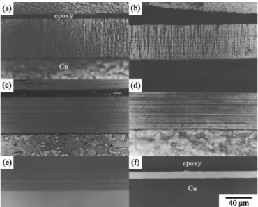
Cross-sectional OM observations.—Figure 2 shows a series of cross-sectional OM micrographs of the deposits plated from the nickel sulfamate baths containing different amounts of H3PO3. When plated at a constant current density, the deposit plated from the sulfamate nickel bath without H3PO3exhibited a coarse colum-nar structure共Fig. 2a兲. These columnar nickel grains grew along the direction of the applied electric field and represented a characteristic of the grain structure of metals electroplated from simple baths.27,28 Adding 1 g dm−3H
3PO3into the bath slightly refined the columnar grains as illustrated in Fig. 2b. Figure 2b also shows a lamellar contrast running parallel to the coating/substrate interface. There-fore, these lamellae were notably perpendicular to the columnar grains. Figure 2c shows that the columnar structure was completely replaced by a layered structure when H3PO3concentration was
fur-ther increased to 1.5 g dm−3. It was also noted that the deposits plated from the baths with the addition of 2-20 g dm−3H
3PO3 re-mained to be a layered structure. However, the grain structure of the deposits plated from the baths containing 30 and 40 g/dm3H
3PO3 was so fine that even after proper chemical etching, the deposit plated from the bath with 40 g m−3 H3PO3 showed a bright and featureless contrast共Fig. 2f兲.
XRD analysis.—Figure 3 shows the XRD patterns of the various deposits. The pure nickel deposit exhibited a关100兴 texture because the intensity ratio of共200兲 to 共111兲 diffractions associated with the deposit was larger than that with nickel powders. For nickel powders the intensity ratio of共200兲:共111兲 diffractions approximately equals 0.5. Such a关100兴 texture was retained when 1 g dm−3H3PO3was added to the solution. The development of lamellar structure shown in Fig. 2b seems to have no effect on the texture of the columnar grains. When bath H3PO3 concentration was further increased to 1.5 g dm−3, a distinct change in deposit texture was observed, i.e., the deposit exhibited a random orientation. As more H3PO3 was added to the baths, the most striking feature on the XRD patterns is Figure 1. Bath pH, deposit phosphorus, and current efficiency as a function
of bath H3PO3concentration.
Figure 2. OM micrographs of共a兲 pure nickel and the Ni-P deposits plated from the bath containing共b兲 1, 共c兲 1.5, 共d兲 10, 共e兲 20, and 共f兲 40 g dm−3 H3PO3.
Figure 3. XRD patterns of共a兲 pure nickel and the Ni-P deposits plated from the bath containing共b兲 1, 共c兲 1.5, 共d兲 5, 共e兲 10, 共f兲 20, and 共g兲 40 g dm−3 H3PO3.
the broadening of the diffraction peaks, particularly the共200兲 peak. A very broad hump was observed on the deposits plated from the bath with 40 g dm−3H3PO3. This result suggests that the coating is amorphous. Because the deposit phosphorus content also increased with H3PO3 concentration, the codeposition of phosphorus in the nickel matrix apparently refined the grain structure of the deposits. The results presented here are consistent with previous studies18,24 showing how the deposit phosphorus content affects the grain size of the deposit. In general, the larger the deposit phosphorus content, the finer the grain size of the deposit becomes.
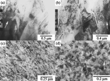
Cross-sectional TEM characterization.—Figure 4 shows the evolution of the grain structure with increasing deposit phosphorus content via cross-sectional TEM. Like OM characterization, the pure nickel deposit exhibited a well-defined columnar structure共Fig. 4a兲. Dislocations and twins were observed, and the twin planes usually inclined at an angle to the columnar axis. This relative orientation between twin plane and columnar axis is a character of the 关100兴-orientated nickel electrodeposit plated from the nickel sulfamate bath.28Figure 4b shows the cross section of the deposit plated from the bath with the addition of 1 g dm−3 H3PO3. The deposit still consisted of columnar grains but had more twins and dislocations than the pure nickel deposit. However, the lamellar contrast on the chemically etched cross section was not observed by TEM. The grain refinement effect associated with codeposited phosphorus be-came more pronounced as H3PO3 concentration was increased to 5 g dm−3. Figure 4c shows that this coating was mainly composed of fibrous grains containing significant lattice distortions. When the H3PO3concentration was increased to 10 g dm−3, the deposit con-tained relatively small equiaxed grains共Fig. 4d兲 but fewer lattice distortions as compared to that plated from the bath containing 5 g dm−3H3PO3.
Figure 5a shows that the deposit plated from the bath with the addition of 20 g dm−3 H
3PO3 exhibited a characteristic layered structure in which the thickness of the layer was approximately 0.2m. Figure 5a also shows that the layer boundary 共marked as the double arrow兲 displayed a light contrast when observed along most incident electron-beam directions. This result signified the layer boundary should contain more light elements, though no com-position difference was discerned between the layer boundary and the interior of the layer. Both contained around 7.6 wt % phos-phorus, as measured by EDS analysis. The dark-field image共Fig. 5b兲 revealed each layer consisted of nanosized grains. It was also noted that the grains of the deposit tended to grow along the direc-tion of the imposed electric field, though these grains were roughly
equiaxed. When H3PO3concentration was increased to 30 g dm−3, the layer thickness and average grain size of the deposit were further reduced, as shown in Fig. 5c. This decrease in layer thickness was more prominent on the deposit plated from the bath with 40 g dm−3 H3PO3. Figure 6 shows that the layered structure was no longer observed on this deposit. Instead, the deposit was a homogeneous structure composed of amorphous matrix with dispersed nanosized crystals. The size of these nanograins, as measured on the dark-field Figure 4. Cross-sectional TEM micrographs:共a兲 pure nickel and the Ni-P
deposits plated from the baths containing共b兲 1, 共c兲 5, and 共d兲 10 g dm−3 H3PO3. The arrow indicates the growth direction of the deposit.
Figure 5. Cross-sectional TEM micrographs:共a,c兲 the Ni-P deposits plated from the baths containing 20 and 30 g dm−3H3PO3, respectively, and共b兲 the corresponding dark-field image of Fig. 5a. The arrow shown in each figure indicates the growth direction of the deposit.
image共Fig. 6b兲, was estimated to be 2 nm. Figure 6c shows the SAD pattern of the deposit. These diffuse halos suggest that the deposit is amorphous, and this finding is consistent with the broad-ened humps shown in the XRD pattern共Fig. 3g兲.
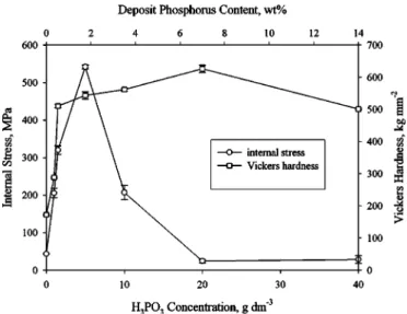
Deposit hardness and internal stress.—Figure 7 shows the hard-ness and internal stress of various deposits as a function of H3PO3 concentration. Following a sharp initial increase with the addition of H3PO3, the deposit hardness steadily increased with increasing
H3PO3concentration up to 20 g dm−3. Further increase in H3PO3 resulted in a slight decrease in the hardness. The transition from a steep to a gradual increase in the hardness coincides with the stages when the deposits exhibited a distinct layered structure after chemi-cal etching, as shown in Fig. 2b and c. Moreover, the deposit asso-ciated with the subsequent increase in the H3PO3concentration un-derwent a decrease in the hardness as it displayed a featureless structure after chemical etching.
Figure 7 also shows the internal stress as a function of deposit phosphorus content, in which the usual sign conventions for stress were adopted, i.e., positive for tensile and negative for compressive. Like the deposit hardness, a sharp increase in the internal stress associated with the deposit was observed as long as a small amount of phosphorus was incorporated in the nickel matrix. After the in-ternal stress reached a peak value, an abrupt decrease was observed when H3PO3concentration was increased from 5 to 10 g dm−3. Fur-ther increase in H3PO3concentration from 20 to 40 g dm−3caused a slight change in the internal stress.
Discussion
Formation of layered Ni-P alloy electrodeposits.—The phos-phorus content of Ni-P electrodeposits increases with increasing H3PO3 concentration; meanwhile the deposit, as characterized by OM on the chemically etched cross section, evolves from a colum-nar structure to a mixture of column and lamella, then a character-istic layered structure, and finally a featureless structure. Concomi-tantly, the grain structure is refined with the incorporation of phosphorus in the deposit. The literature clearly demonstrates that the incorporation of phosphorus refines the grain structure of Ni-P electrodeposits.18,24 The deposits could become amorphous when the deposit phosphorus content exceeds a critical value.18-20,24 More-over, some electrodeposited and electroless Ni-P alloys have been shown to exhibit a layered structure after proper chemical etching.1,23,29However, OM and TEM characterization on the Ni-P electrodeposits with a whole composition spectrum remains essen-tial to elucidate the mechanism related to the formation of layered deposits.
The results presented here clearly illustrate that increasing bath H3PO3concentration reduces the current efficiency because more cathodic charges are expended in reduction of protons. Proton re-duction results in the atomic and molecular forms of hydrogen. Both can be incorporated in the deposit as atomic or molecular forms,8,29,30which affects the texture31and internal stress23,26,32of the coating. In the meantime, hydrogen molecules can also merge to form hydrogen bubbles clinging to the surface of the electrode共Fig. Figure 6. Cross-sectional TEM micrographs of the Ni-P deposit plated from
the bath containing 40 g dm−3H3PO3:共a兲 bright-field, 共b兲 dark-field images, and共c兲 SAD pattern.
Figure 7. Effect of bath H3PO3concentration on the hardness and tensile stress in the deposit.
8a兲. Furthermore, the pH at the electrode/solution interface rises concomitantly with the discharge of protons.14,29Once some of the hydrogen bubbles grow to a critical size, they escape from the cath-ode and trigger the overall collapse of the other relatively small bubbles. Enhanced convection due to evolved gas bubbles increases the interfacial proton concentration共Fig. 8b兲. Consequently, proton concentration at the electrode/solution interface varies periodically due to the formation and subsequent escape of hydrogen bubbles as the deposit grows. According to the codeposition mechanism, the incorporation of phosphorus in the deposit depends on the pH, i.e., proton concentration, of the solution regardless of direct or indirect codeposition mechanisms.1,13-17Therefore, interfacial pH variations should cause the variation in the deposit phosphorus content as elec-troplating continues. For example, the lamellas observed on the de-posit plated from the bath with the addition of 1 g dm−3 H
3PO3
共Fig. 2b兲 are believed to be due to the slight variation in phosphorus
content because the deposit still has a关100兴 texture, characteristic of the coarse columnar nickel grains.28TEM also shows that the layer boundary seems to contain more phosphorus than the interior of each layer. Crousier et al.29have confirmed that the layered Ni-P electrodeposits consist alternately of layers with different phos-phorus contents.
Other reactions causing changes of the pH at the interface poten-tially occur during electroplating. For example, reduction of H3PO3 to either phosphorus or phosphine consumes protons, while
reduc-this study measures the average stress of the deposit in which there could be highly localized stresses of both a tensile and com-pressive nature. However, the average stress of the deposit should reveal the most dominant mechanism for the evolvement of the local stress if an overall uniformity of the deposit through its thickness can be obtained.33When electroplated in the nickel sulfamate bath with various amounts of H3PO3, all the Ni-P deposits studied exhibit a tensile stress that has a maximum at intermediate deposit phos-phorus content. Furthermore, the internal stress exhibits a distinct change as the coating microstructure changes with the deposit phos-phorus content. Therefore, the internal stress seems to be related to proton discharge and crystallite joining during electroplating.
A general review of the origins of stress in electrodeposits given by Weil summarizes five possible theories: crystallite joining, hydro-gen, changes in foreign substances, excess energy, and lattice defects.32Hydrogen incorporation can cause both tensile and com-pressive stresses. A comcom-pressive stress is induced when hydrogen either stays in the interstices of or forms gas pockets in the deposit,26,32while a tensile stress is associated with the decrease in volume when the codeposited hydrogen leaves again.8,32,34Because voids were hardly observed even in the deposit plated at 32% ca-thodic efficiency共Fig. 1 and 6兲, the gas pockets, if they exist in the deposit, are unlikely to play an important role in the internal stress of all the deposits investigated. Instead, tensile stresses can occur when the hydrogen, which is incorporated in the deposit as a result of proton discharge and hydrogen absorption, diffuses out of the deposit, because all of the deposits studied exhibit a tensile stress regardless of their phosphorus contents. Paseka7studied evolution of hydrogen and its sorption in Ni-P electrodeposits and found that the amount of absorbed hydrogen depends on the deposit phosphorus content and has a maximum at intermediate deposit phosphorus con-tent. Burchardt10also noted a volcano-shaped curve for the depen-dence of the rate of the hydrogen evolution reaction共HER兲 on the deposit phosphorus content, signifying a maximum activity associ-ated with the deposits with intermediate phosphorus content. Fur-thermore, the most active Ni-P electrodes absorb the largest amount of hydrogen. Because the internal stress vs. the deposit phosphorus content plot also shows a volcano-shaped curve共Fig. 7兲, the peak stress of the deposit is probably related to the escape of a maximum amount of absorbed hydrogen that is subsequently incorporated in the deposit with continued electroplating. Boric acid, which tends to stabilize the interfacial pH to a value close to the bulk nickel sulfa-mate solution, has been shown to effectively suppress hydrogen evo-lution during high-speed electroplating and thus produce the nickel films with low internal stresses.34
Another close-related phenomenon is the evolution of the grain structure and internal stress of the deposits with increasing deposit phosphorus content. The maximum tensile stress of the deposit oc-curs at critical deposit phosphorus content when the coating consists of fibrous grains that undergo the most serious lattice distortions among the deposits studied. Below this critical value the coating exhibits a columnar structure, while above that the coating displays an equiaxed grain structure. Consequently, the crystallite-joining theory might, to some extent, account for the internal stress of the deposit. For example, upon electrocrystallization, the crystallites, Figure 8. Schematic representations illustrating the periodic variations in
interfacial proton concentration as electroplating proceeds:共a兲 a decrease in the proton concentration when hydrogen bubbles form due to the discharge of protons, and共b兲 an increase in the proton concentration when the hydro-gen bubbles collapse as some of the bubbles have grown to a critical size.
which form via three-dimensional nucleation, grow and touch each other. Subsequent coalescence causes a tensile stress because the different crystallites, when they touch each other, would be pulled together by a surface tension so as to reduce the total free surface energy. This pulling force depends on the grain shape, size, and preferred orientation of the deposit. For example, most deposits that exhibit relatively high internal stresses consist of columnar grains on which the pulling force developed upon merging the columnar grains together should be linear with the thickness of the deposit.32 Larger column grains could increase the internal stress because the boundary mismatch would be greater, but fewer unfilled gaps asso-ciated with larger grains would reduce the internal stress. The pure sulfamate nickel plated in this study has a relatively low stress be-cause of its relatively coarse columnar grains with共200兲 texture.34 Phosphorus incorporation refines the grain structure and results in more randomized fibrous grains. The increase in mismatch between random fibrous grains and in unfilled gaps associated with the finer grains causes an increase in the internal stress. Meanwhile, the coa-lescence of these fibrous grains could result in serious lattice distor-tions induced by a larger pulling force. When phosphorus in the deposit exceeds a critical amount, the development of long fibrous grains is inhibited. Instead, equiaxed grains form共Fig. 4兲. As fibrous grains are replaced by equiaxed grains, one would expect a de-creased tensile stress because smaller crystallites, as merging to-gether, result in smaller pulling force. Smaller pulling forces induce fewer lattice defects in the deposit, as evident from the fact that fibrous grains contain more dislocations than equiaxed grains. How-ever, as electroplating proceeds, nucleation, growth, and coalescence of the equiaxed grains on the existing coating layer might result in a complicated stress distribution through the thickness of the deposit. Finally, a slight decrease in the internal stress was observed as the deposit comprises amorphous matrix with dispersed nanocrystals. Apparently, near amorphous structure, lattice mismatch contributes less to the internal stress.
Conclusions
This study demonstrates that the hardness and internal stress of the Ni-P electrodeposit are well related to its microstructure, which changes with the phosphorus content in the deposit. Several key findings are summarized as the following.
1. More phosphorus is incorporated when more H3PO3is added to the nickel sulfamate bath, while the current efficiency monoto-nously decreases with increasing bath H3PO3.
2. As the bath H3PO3 is increased, the hardness of the deposit increases abruptly, followed by a gradual increase, and finally a slight decrease as 40 g dm−3H
3PO3is added. The tensile stress in the deposit also escalates with increasing bath H3PO3and reaches a maximum value at 5 g dm−3H
3PO3. Further increase in bath H3PO3 reduces the tensile stress in the deposit.
3. The overall structural evolution shown on chemically etched cross sections with increasing bath H3PO3shows, in order, column, the coexistence of column and lamella, a characteristic layer, and finally a featureless structure.
4. Both columnar pure nickel and Ni-P electrodeposits exhibit a
关100兴 texture, while layered Ni-P deposits generally display a
ran-dom texture. The XRD pattern of the deposit that shows featureless after chemical etching contains broadened humps.
5. When the nickel deposit is alloyed with phosphorus by adding H3PO3in the nickel sulfamate bath, an initial incorporation of phos-phorus refines the columnar grain structure and introduces more lattice defects. The development of columnar grains is inhibited and the equiaxed grains form as bath H3PO3 concentration exceeds a
critical amount. Further increase in bath H3PO3 concentration re-sults in the deposit composed of amorphous matrix dispersed with nanograins.
6. The layered structure associated with Ni-P deposits appears to be related to periodic variations in interfacial pH, which changes with reduction of protons, H3PO3, and phosphine, as well as en-hanced convection induced by evolved gas bubbles.
7. The fact that both the internal stress and amount of absorbed hydrogen have a maximum at intermediate phosphorus contents sug-gests that hydrogen incorporation in and subsequent escape from the deposit plays an important role in the internal stress of Ni-P elec-trodeposits.
Acknowledgments
This research was supported by the National Science Council, Republic of China, under grant no. 91-2216-E-002-040. L. C. Wang, National Sun Yat-sen University, is recognized for her assistance with the TEM work. This study made use of the electron probe microanalyzer and electron microscopes of National Taiwan Univer-sity and electron microscopes of National Sun Yat-sen UniverUniver-sity, supported by the National Science Council, Republic of China.
National Taiwan University assisted in meeting the publication costs of this article.
References
1. M. Ratzker, D. S. Lashmore, and K. W. Pratt, Plat. Surf. Finish., 73共9兲, 74 共1986兲. 2. R. Weil, J. H. Lee, and K. Parker, Plat. Surf. Finish., 137共2兲, 76 共1989兲. 3. C. J. Chen and K. L. Lin, Thin Solid Films, 370, 106共2000兲. 4. B. P. Daly and F. J. Barry, Int. Mater. Rev., 48, 326共2003兲. 5. C. C. Hu and A. Bai, J. Appl. Electrochem., 31, 565共2001兲. 6. C. C. Hu and A. Bai, Mater. Chem. Phys., 77, 215共2003兲. 7. I. Paseka, Electrochim. Acta, 40, 1633共1995兲.
8. I. Paseka, Electrochim. Acta, 47, 921共2001兲. 9. T. Burchardt, Int. J. Hydrogen Energy, 25, 627共2000兲.
10. T. Burchardt, V. Hansen, and T. Valand, Electrochim. Acta, 46, 2761共2001兲. 11. R. K. Shervedani and A. Lasia, J. Electrochem. Soc., 144, 511共1997兲. 12. A. Brenner, Electrodeposition of Alloys, Vol. II, Academic Press, New York共1963兲. 13. T. Morikawa, T. Nakade, M. Yokoi, Y. Fukumoto, and C. Iwakura, Electrochim.
Acta, 42, 115共1997兲.
14. R. L. Zeller III and U. Landau, J. Electrochem. Soc., 139, 3464共1992兲. 15. T. M. Harris and Q. D. Dang, J. Electrochem. Soc., 140, 81共1993兲. 16. Y. Zeng and S. Zhou, J. Electroanal. Chem., 469, 79共1999兲.
17. M. Saitou, Y. Okudaira, and W. Oshikawa, J. Electrochem. Soc., 150, C140共2003兲. 18. E. Bredael, B. Blanpain, J. P. Celis, and J. R. Roos, J. Electrochem. Soc., 141, 294
共1994兲.
19. E. Vafaei-Makhsoos, E. L. Thomas, and L. E. Toth, Metall. Trans. A, 9, 1449
共1978兲.
20. K. Shimizu, G. E. Thompson, G. C. Wood, and K. Kobayashi, Philos. Mag. Lett.,
61, 43共1990兲.
21. R. D. Fisher, J. Electrochem. Soc., 109, 479共1962兲. 22. D. Baudrand, Met. Finish., 94共7兲, 15 共1996兲.
23. M. H. Seo, J. S. Kim, W. S. Hwang, D. J. Kim, S. S. Hwang, and B. S. Chun, Surf.
Coat. Technol., 176, 135共2004兲.
24. G. McMahon and U. Erb, J. Mater. Sci. Lett., 8, 865共1989兲. 25. R. Narayan and M. N. Mungole, Surf. Technol., 24, 233共1985兲.
26. H. D. Park, D. Chang, K. H. Lee, and S. G. Kang, Plat. Surf. Finish., 88共12兲, 64
共2001兲.
27. J. W. Dini, Electrodeposition, 1st ed., p. 141, Noyes Publications, Park Ridge, NJ
共1993兲.
28. C. S. Lin, K. C. Peng, P. C. Hsu, L. Chang, and C. H. Chen, Mater. Trans., JIM,
41, 777共2000兲.
29. J. Crousier, Z. Hanane, and J.-P. Crousier, Thin Solid Films, 248, 51共1994兲. 30. R. L. Zeller III and U. Landau, J. Electrochem. Soc., 137, 1107共1990兲. 31. J. Amblard, I. Epelboin, M. Froment, and G. Maurin, J. Appl. Electrochem., 9, 233
共1979兲.
32. R. Weil, Plating, 58共2兲, 137 共1971兲.
33. G. S. Sotirova-Chakarova and S. A. Armyanov, J. Electrochem. Soc., 137, 3551
共1990兲.