國立交通大學
電控工程研究所
碩士論文
智慧型字卡影像辨識系統設計
Intelligent Word Card Image
Recognition System Design
研 究 生 : 孫 齊
指導教授 : 陳永平 教授
智慧型字卡影像辨識系統設計
Intelligent Word Card Image Recognition System Design
研 究 生 : 孫 齊 Student : Chi-Sun
指導教授 : 陳永平 Advisor : Yon-Ping Chen
國 立 交 通 大 學
電 控 工 程 研 究 所
碩 士 論 文
A Thesis
Submitted to Institute of Electrical Control Engineering College of Electrical and Computer Engineering
National Chiao Tung University In Part Fulfillment off the Requirements
for the Degree of Master in
Electrical Control Engineering June 2012/6/12
Hsinchu, Taiwan, Republic of China 中華民國一百零一年六月
i
智慧型
字卡影像辨識系統設計
學生: 孫齊 指導教授: 陳永平 教授
國立交通大學電機與控制工程學系
摘 要
本篇論文的研究目的是希望能製做出一系統,能使童伴機器人與孩童進行互 動,並從中學習單字。系統被設計成三個步驟,包含抽取物件的區域、抽取字元 以及字元辨識。本篇論文有主要兩個貢獻,第一部分是特定顏色移動物的辨識。 第二部分是在不同大小、傾斜以旋轉中的字元辨識。在特定顏色移動物的辨識中, 一般所知的是顏色辨識與移動物辨識兩步驟。本篇論文在此使用類神經演算法將 一般所知的兩個步驟改成同時進行。此外在針對文字辨識中,我們使用熟知的標 楷體來做辨識,此系統可以在不同位置、大小、傾斜程度以及任意的旋轉角度中, 達到成功的辨識。最後,三個實驗將會驗證系統的成功開發。ii
Intelligent Word Card Image
Recognition System Design
Student
:
Chi Sun Advisor:Prof. Yon-Ping Chen
Institute of Electrical Control Engineering
National Chiao-Tung University
ABSTRACT
The purpose of this thesis is to build up a system for children to learn words in an interactive way. The system is designed in three steps, including potential object localization, character extraction and character recognition. The main contribution of this thesis includes two parts, which are the moving object detection and the image recognition. The moving object is an word card in special color and the image to be recognized is a character. To detect the moving word card from a sequence of images, an artificial neural network is proposed to extract the color and detect the word card simultaneously. After the word card is detected, a scheme based on a set of concentric circles is applied to extract the features of the character on the word card. From the features, another artificial neural network is designed for character recognition invariant to the translation, rotation and scaling of the word card. Finally, the success of the developed system is verified by three experiments.
iii
Acknowledgement
本篇論文得以完成,首先必須誠摯感謝指導教授 陳永平老師在這兩年中的 悉心指導與教誨。老師嚴謹的治學態度,理論與實務並重的訓練,使得本論文得 以順利完成。除了學術上的指導,在待人處事方面的啟發更是讓我獲益良多,這 份師恩會令我永生難忘。同時也感謝 林進燈老師與楊谷洋老師對本論文所提出 的珍貴意見與指正,使得本論文得以更佳的完整。 此外,感謝可變結構控制實驗室的世宏學長、桓展、文榜、澤翰與文俊學長 在平日攻讀學位之餘,不吝嗇傳授知識與經驗及給予建議。同時,感謝實驗室同 學榮哲、振方、崇賢、咨瑋以及學弟谷穎、宣俊、仕政、兆村在課業與研究上一 起學習、勉勵以及協助使我收穫良多。 最後,感謝這一路相輔相持的慈珊、詩屏、振綱與玉青,你們在生活中帶給 我的許多歡樂,使我生活多采多姿,為我兩年的研究生活帶來許多歡樂及回憶。 更感謝我的母親、大哥、二哥,你們的關心與鼓勵,給了我許多的溫暖,由於你 們的支持,使我能專心研究。 僅以此篇論文獻給所有關心我、照顧我的人,你們的恩惠我銘感於心,由衷 的感謝你們。 孫齊 2012.7iv
Contents
Chinese Abstract ... i
English Abstract ... ii
Contents ... iv
List of Figure ... vii
List of Tables ... ix
Chapter 1 Introduction
...1
1.1 Motivation ...1
1.2 System Overview ...2
Chapter 2 Related Work ... 5
2.1 Introduction to ANNs ...5
2.2 Back-Propagation Network ...7
2.3 Foreground Segmentation ... 11
2.4 Introduction to Morphology Operation ... 12
2.5 Color Detection ... 14
2.6 Character Recognition ... 15
Chapter 3 Intelligent Word Card Image
Recognition System ... 18
v
3.1 Detection of Moving Object in special color ... 19
3.2 Morphology Operation ... 22
3.2.1 Erosion and Dilation ... 22
3.2.2 Holes filling ... 24
3.3 Connected Components Labeling ... 25
3.4 Character extraction from Potential Region ... 28
3.4.1 Color Extraction ... 28
3.4.2 Character Extraction ... 30
3.5 Character recognition ... 31
3.5.1 Feature Extraction ... 31
3.5.2 Classification with Neural Networks ... 33
Chapter 4 Experiments ... 34
4.1 Part I: Result of Each Steps ... 36
4.1.1 Result of Potential Object Localization ... 36
4.1.2 Result of Character Extraction ... 38
4.1.3 Result of Feature Extraction ... 39
4.1.4 Result of Classification ... 40
4.2 Part II: Intelligent system ... 42
4.2.1 Morphology operation with Artificial Neural Network... 42
4.2.2 Detect Moving Object Card in several Color with Artificial Neural network ... 45
4.3 Part III: Execution time ... 47
Chapter 5 Conclusion and Future works ... 50
vi
List of Figures
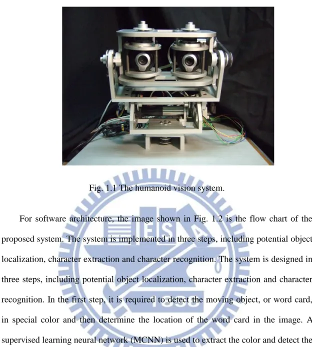
Fig. 1.1 The humanoid vision system ... 3
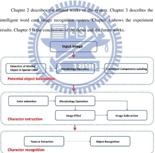
Fig. 1.2 The software architecture ... 4
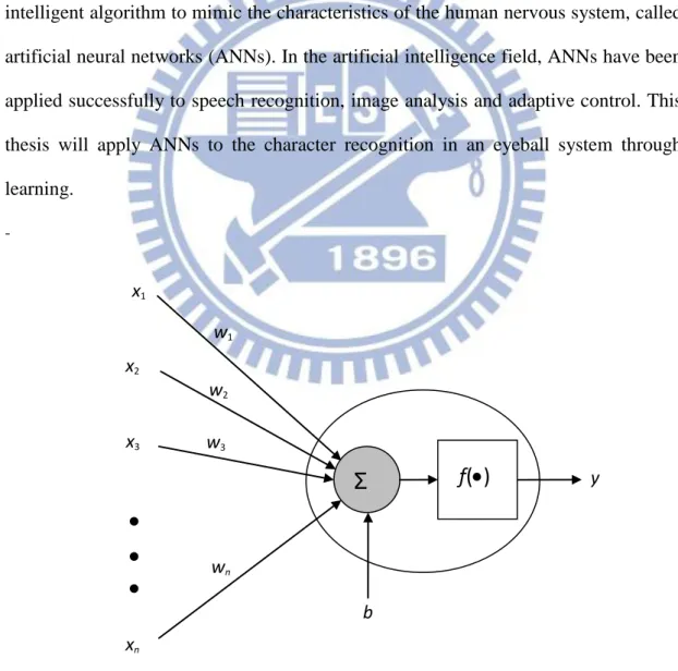
Fig. 2.1 Basic structure of a neuron ... 5
Fig. 2.2 A multilayer feed-forward network with two hidden layers ... 7
Fig. 2.3 Neural network with one hidden layer ... 8
Fig. 2.4 Example of dilation ... 13
Fig. 2.5 Example of erosion ... 14
Fig. 2.6 Flow chart of character recognition ... 15
Fig. 2.7 (a),(b) Example of feature extraction ... 17
Fig. 3.1 The flow chart of the intelligent system ... 18
Fig. 3.2 (a) Input image (T=t-1). (b) Input image (T=t) ... 19
Fig. 3.2 (c) Moving detection ( (d) Detection of moving object in special color ( ... 20
Fig. 3.3 MCNN’s structure... 20
Fig. 3.4 MCNN ... 21
vii
Fig. 3.6 Steps for morphology operations (a) Initial image (b) Result of erosion using
structuring element B. (c) Result of dilation using structuring element C ... 23
Fig. 3.7 (a) A. (b) Ac . (c) B ... 24
Fig.3.8 (a) Original frame. (b) Result of holes filling. ... 25
Fig. 3.9 Scanning the image ... 25
Fig. 3.10 Example of 4-pixel connected CCL. (a) Digital image. (b) Labeling (c) Componentizing ... 27
Fig. 3.11 Examples of training data for skin color extraction.(a) Original image (b) Skin color region (c) Background ... 28
Fig. 3.12 Neural network structure for color extraction ... 29
Fig. 3.13 GNN ... 30
Fig. 3.14 (a) Result after reduced the noise. (b) Image with hole filled. (c) Image subtraction ... 31
Fig. 3.15 Example of major axis length and minor axis length ... 32
Fig. 3.16 CRNN structure ... 33
Fig. 3.17 CRNN ... 35
Fig. 4.1 (a) Input image (T=t-1). (b) Input image (T=t) ... 37
viii
Fig. 4.3 (a) Erosion. (b) Dilation. ... 37
Fig. 4.4 CCL ... 37
Fig. 4.5 More example for extraction.(a) Detection of moving object in special color. (b) Result after morphology operation. (c) Result after CCL ... 38
Fig. 4.6 (a) Potential region. (b) Color extraction. (c) Reduce the noise. (d) Filled image. (e) Character extraction. ... 39
Fig. 4.7 More example for character extraction. (a) Potential region. (b) Color extraction. (c) Reduce the noise. (d) Filled image. (e) Character extraction ... 39
Fig. 4.8 Example for classification ... 41
Fig. 4.9 Examples of training data for character recognition. ... 42
Fig.4.10 System flowchart. ... 44
Fig.4.11 Neural network structure for morphology operation. ... 45
Fig. 4.12 (a) Square block (b) Scanning the image. ... 45
Fig. 4.13 (a) Original image.(b) The result with using MONNE. (c) The result with using MONND. ... 46
Fig.4.14 Neural network structure for SCNN1 and SCNN2. ... 46
Fig. 4.15 (a) Input image (T=t-1). (b) (T=t). (c) The result with using SCNN1. ... 47
ix
List of Tables
Table. 4.1 Same image size with different angle. ... 40
Table. 4.2 Same aspect ratio with different scale. ... 40
Table. 4.3 Different aspect ratio with the original size is 315×300 ... 41
Table. 4.4 Different training data with CRNN ... 43
Table. 4.5 Different condition with CRNN ... 43
Table 4.6 MONNE’s execution time in different block sizes ... 49
Table 4.7 SCNN1’s execution time in different block sizes ... 49
1
Chapter 1
Introduction
1.1 Motivation
In recent years, our laboratory research gradually developed. There are two major parts in our laboratory researches, intelligent machine learning [1],[2] and application of kinder robot.
There are a lot of algorithms used in detection and recognition systems. Expect the higher performance, the algorithm will be more complex and system rules will be harder to find. Artificial neural networks (ANNs) are intelligent machine learning systems that are deliberately constructed to make use of some organizational principles resembling those of the human brain, which can learn to find out the correct results and make the system easier to implement and extent.
The other part in our laboratory research is the application of kinder robot. As the technicalization of children’s products gradually extracts attention, how to achieve better educational result when using children’s products with electronic technique becomes more important.
Like several thesis in our laboratory research, “Intelligent human detection system design based on depth information” and “Design of Wireless-Based Remote Interaction System Applied to Remote Surveillance”, etc. This thesis is to design a system by using the results of the three seniors’ work. We combine the color extraction in the face recognition system, the identification of the moving objects in
2
the pedestrian recognition system and the character recognition in the license plate recognition system. The purpose of this thesis is to build up a system for children to learn words in an interactive way.
1.2 System Overview
For hardware architecture, the system shown in Fig. 1.1 is established by setting two cameras on a horizontal line and their lines of vision are parallel and fixed. In addition, the distance between two cameras is set as constant equal to 10 cm and these two cameras, QuickCamTM Communicate Deluxe, have specification listed below. The experimental environment for testing is our laboratory and the deepest depth of the background is 400 cm.
1.3-megapixel sensor with RightLight™2 Technology
Built-in microphone with RightSound™ Technology
Video capture: Up to 1280 x 1024 pixels (HD quality) (HD Video 960 x 720 pixels)
Frame rate: Up to 30 frames per second
Still image capture: 5 megapixels (with software enhancement)
USB 2.0 certified
3
Fig. 1.1 The humanoid vision system.
For software architecture, the image shown in Fig. 1.2 is the flow chart of the proposed system. The system is implemented in three steps, including potential object localization, character extraction and character recognition. The system is designed in three steps, including potential object localization, character extraction and character recognition. In the first step, it is required to detect the moving object, or word card, in special color and then determine the location of the word card in the image. A supervised learning neural network (MCNN) is used to extract the color and detect the moving word card simultaneously. After applying the MCNN, the region of the word card in green color is extracted from a sequence of images; unfortunately, some noise exists therein. Using morphology operation and connected components labeling (CCL), the noise is removed and the region of the word card could be located correctly.
In the second step, use another supervised learning neural network (GNN) to detect the green color of the word card, and then apply the morphology operation to reduce noise. The word card is thus achieved as a binary image with the shape of the
4
character on it. By generating a plain binary card, the character on the word card can be extracted by subtracting the plain binary card. Besides, the total number of pixels of the character is calculated to determine whether the result is a character or not. In the third step, a scheme based on a set of concentric circles is adopted to extract the character features, and then feed the features into the third supervised learning neural network (CRNN) to recognize which word it is, the designed neural networks CRNN can robustly identify characters in different translation, size, tilt and angle of rotation [3]. The overall system processing time is about 0.15s.
Chapter 2 describes the related works of the system. Chapter 3 describes the intelligent word card image recognition system. Chapter 4 shows the experiment results. Chapter 5 is the conclusions of the thesis and the future works.
5
Chapter 2
Related Work
2.1 Introduction to ANNs
The human nervous system consists of a large amount of neurons, including somas, axons, dendrites and synapses. Each neuron is capable of receiving, processing, and passing signals from one to another. Recently, investigators have developed an intelligent algorithm to mimic the characteristics of the human nervous system, called artificial neural networks (ANNs). In the artificial intelligence field, ANNs have been applied successfully to speech recognition, image analysis and adaptive control. This thesis will apply ANNs to the character recognition in an eyeball system through learning. -w1 w2 w3 wn b x2 x3 xn x1 y
f(
)
Σ
6
Fig. 2.1 shows the basic structure of a neuron, whose input-output relationship can be described as 1 n i i i y f w x b
(2.1)where xi and wi are respectively the i-th input and its weight, b is the bias, and y
represents the output. As for the activation function f(), it can be linear or nonlinear, and its activation level is determined by the sum of wixi and the bias b. Here list three
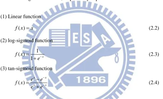
types of the commonest activation functions, called the linear function, log-sigmoid function and tan-sigmoid function, respectively expressed as below:
(1) Linear function ( ) f x x (2.2) (2) log-sigmoid function 1 ( ) 1 x f x e (2.3) (3) tan-sigmoid function ( ) x x x x e e f x e e (2.4)
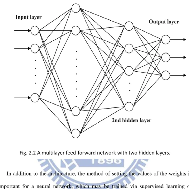
The structure of a multilayer feed-forward network is generally composed of one input layer, one output layer, and some hidden layers. For example, Fig. 2.2 shows a multilayer feed-forward network with one input layer, one output layer, and two hidden layers. Each layer is formed by neurons with basic structure depicted in Fig. 2.1. The input layer receives signals from the outside world, and then responses through the hidden layers to the output layer. Note that in some cases only the input layer and output layer are required, with the hidden layers omitted.
Compared with the network using single hidden layer, the network with multi-hidden layers can solve more complicated problems. However, its related
7
training process may become more difficult.
Fig. 2.2 Multilayer feed-fo
In addition to the architecture, the method of setting the values of the weights is important for a neural network, which may be trained via supervised learning or unsupervised learning. Training of supervised learning is mapping a given set of inputs to a specified set of target outputs. The weights are then adjusted according to various learning algorithms. As for the unsupervised learning, the neural network is trained to group similar input vectors together without any training data to specify what a typical member of each group looks like or which group each vector belongs to. In this thesis, the neural network learns the behavior by many input-output pairs, hence that is belongs to supervised learning.
8
2.2 Back-Propagation Network
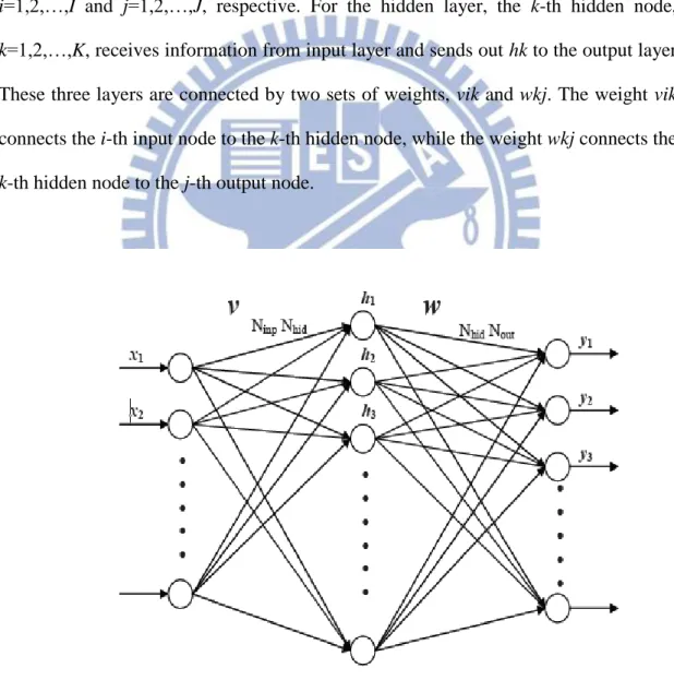
The back propagation, BP in brief, was proposed in 1986 by Werbos, etc. [], which is based on the gradient steepest descent method to update the weights by minimizing the total square error of the output. The BP algorithm has been widely used in a diversity of applications with supervised learning. To clearly explain the BP algorithm, an example is given in Fig. 2.3, a neural network with I input nodes, J output nodes, and K hidden nodes. Let the inputs and outputs be xi, and yj, where
i=1,2,…,I and j=1,2,…,J, respective. For the hidden layer, the k-th hidden node, k=1,2,…,K, receives information from input layer and sends out hk to the output layer.
These three layers are connected by two sets of weights, vik and wkj. The weight vik connects the i-th input node to the k-th hidden node, while the weight wkj connects the
k-th hidden node to the j-th output node.
9
Based on the neural network in Fig. 2.3, the BP algorithm for supervised learning is generally processed by eight steps as below:
Step 1: Set the maximum tolerable error Emax and then the learning rate between 0.1 and 1.0 to reduce the computing time or increase the precision.
Step 2: Set the initial weight and bias value of the network randomly.
Step 3: Input the training data, x[x1 x2 xI]T and the desired output
1 2
[ J]T
d d d d .
Step 4: Calculate each output of the K neurons in hidden layer 1 , 1, 2..., I k h ik i i h f v x k K
(2.5)where fh() is the activation function, and then each output of the J neurons
in output layer 1 , 1, 2..., K j y kj k k y f w h j J
(2.6)where fy() is the activation function.
Step 5: Calculate the following error function
2 2 1 1 1 1 1 ( ) ( ) 2 2 J J K j j j y kj k j j k E w d y d f w h
(2.7)where d is the desired output.
Step 6: According to gradient descent method, determine the correction of weights as below:
10 j kj kj k kj j kj y E E w h w y w (2.8) 1 J j k ik ikj i j ik j k ik y E E h v x v y h v
(2.9) where 1 ( ) K kj j j y kj k k d y f w h
1 1 1 ( ) J K I ikj j j y kj k kj h ik i j k i d y f w h w f v x
Step 7: Propagate the correction backward to update the weights as below:
( 1) ( ) ( 1) ( ) w n w n w v n v n v (2.10)
Step 8: Check the next training data. If it exists, then go to Step 3, otherwise, go to Step 9.
Step 9: Check whether the network converges or not. If EEmax, terminate the training process, otherwise, begin another learning circle by going to Step 1.
The maximum tolerable error Emax are the same as error function. Learning rate is the parameters can change the speed on correction the weights .BP learning algorithm can be used to model various complicated nonlinear functions. Recently, the BP learning algorithm is successfully applied to many domain applications, such as: pattern recognition, adaptive control, clustering problem, etc. In the thesis, the BP algorithm was used to learn the input-output relationship for clustering problem.
11
2.3 Foreground Segmentation
Dynamic imaging is often the part of interest in the real-time detection system, a good motion detection system to identify moving objects in the picture can get great help for the next classification, or tracking. So a good dynamic detection method can provide more accurate information for follow-up action. There are three common way: background subtraction [7], and optical flow [8], frame difference [9].
Background subtraction is the most common method for segmentation of interesting regions in videos. This method has to build the initial background model firstly. The purpose of training background model is to subtract background image from current image for obtaining interesting foreground regions. Background subtraction method can detect the most complete of feature points of interesting foreground regions and real-time implementation.
Optical flow reflects the image changes due to motion during a time interval, and the optical flow field is the velocity field that represents the three-dimensional motion of foreground points across a two-dimensional image. Compared with other two methods, optical flow can be more accurate to detect interesting foreground region. But optical flow computations are very intensive and difficult to realize in real time.
Frame difference method is to do pixel-based subtraction in successive frames. Its original reasonable is using consistency continuous image background subtraction, image segmentation algorithms such as
is image subtraction matrix, and are representatives
12
(Subth) for change detection, when Isub(x,y) level of abnormal larger than this
threshold can be regarded as a dynamic pixel, otherwise identified as the background.
1
1 1 , , , 0 , , t t t h sub t t th I x y I x y Sub I x y I x y I x y Sub (2.12)This method can quickly adapt to change of illumination and camera motion and lower computation. This study considers the environment and the processing time and other factors, the use of frame difference as the prospect of capture method.
2.4 Introduction to Morphology Operation
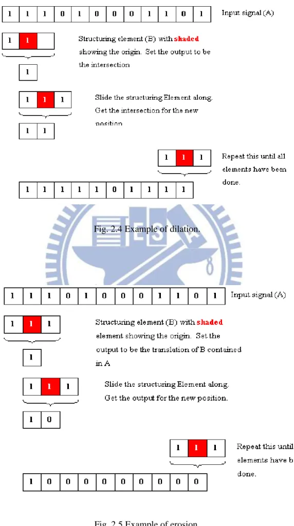
Morphology has two simple functions, dilation and erosion [10]. Dilation is defined as:
: ( )ˆ
x
A B x B A (2.13)
where A and B are sets in Z. This equation simply means that B is moved over A and the intersection of B reflected and translated with A is found. Usually A will be the signal or image being operated on and B will be the structuring element. Fig. 2.4 Shows how dilation works.
The opposite of dilation is known as erosion. This is defined as:
: ( )x
A B x B A (2.14)
which simply says erosion of A by B is the set of points x such that B, translated by x, is contained in A. Fig. 2.5 shows how erosion works. This works in exactly the same way as dilation. However equation (2.2) essentially says that for the output to be a one, all of the inputs must be the same as the structuring element. Thus, erosion will remove runs of ones that are shorter than the structuring element. This thesis will applied two kind of this operation to process the image.
13
Fig. 2.4 Example of dilation.
14
2.5 Color Detection
Color is an important source of information during the human visual perception activities. There are some popular research topic like detecting and tracking human faces and gestures. Different color detection has applied to a variety of tasks, we can chose the color we want and using filter in web image contents, for examples about skin color like detecting and tracking human faces and gestures, and diagnosing disease [11],[12],[13].
As the first task in detection of moving object in special color and character extraction technique in our schemes, color detection can highly reduce the computational cost [14], and then extracts the potential object regions and character. Furthermore, color image segmentation is computationally fast while being relatively robust to changes in scale, viewpoint, and complex background.
According to the characteristics of module in color space distribution, the color of pixel can be detected quickly by a module’s color model. However the use of different color spaces for different races and different illuminations often results in different detection accuracy [15]. In this thesis, the experimental environment is our laboratory and the lighting condition is fixed.
Usually, the color detection should be considered two aspects: color space selection and how to use the color distribution to establish a good color model. Nowadays main color spaces include RGB, HSV, HSI, YCbCr, some of their variant,
15
2.6 Character recognition
In character recognition applications, it can be divided into two categories, Optical Character Recognition (OCR) and On Line Character Recognition (OLCR). The OLCR uses a handwritten board or digital pen as an input tool to get the characters and then implement the character recognition. Different from the OLCR, The OCR uses a scanner to scan a document and save it as an image file, and then identifies the characters in the image file. This thesis will adopt the OCR for character recognition since the characters to be recognized are attained from a sequence of images.
The basic flow chart of the character recognition is shown in Fig.2.6. In general, the pre-processing of an image contains the object location, size normalization, binarization, angle of rotation, tilt, etc. There are two main parts in the character recognition system, which are feature extraction and feature classification. They are related to the speed and accuracy in text recognition. In these steps, many methods have been proposed and they can be divided into three types: Statistics method, Structure method, Merger Statistics and Structure method.
The main part in statistical method is to measure the composition of some particular physical quantities in the image. It’s usually extracted text features or characteristics, to classify and by matching the pattern in built-in database. Basically,
16
it’s easy to make such character, have fast calculation, and often organized into a vector. Therefore, the feature space of the text image can be mapped to the point, when the point is closest to the one-word characteristic distribution, this image is judged as a text.
Structure method is using the geometric structure of the text, and setting description language to represent text which usually based on the structure of the characters. Word is split into several parts and compare with built-in database in order to determine the most similar result. In general, the structure method can tolerate its own variability. But the reaction with interference of noise is unstable. For example: template matching method.
Merger Statistics and Structure method combined the advantages in two ways. This thesis used merger statistics and structure method and mainly refers to this literature on the feature extraction, Torres-Mendez, L.A. “Translation, Rotation, and Scale-Invariant Object Recognition” [16].The paper presents a method for object recognition that achieves excellent invariance under translation, rotation, and scaling. In the feature extraction, it takes into account the invariant properties of the normalized moment of inertia [17] and a novel coding that extracts topological object characteristics [18].
The feature extraction is based on a set of concentric circles which are naturally and perfectly invariant to rotation (in 2-D). Fig. 2.7(a) shows an example with 8 concentric circles. Each circle is cut into some arcs by the character. Heuristically, the number of arcs of the i-th outside the character can be used as the first feature, denoted as Mi. This simple coding scheme extracts the topological characteristics of
the object regardless of its position, orientation, and size. However, in some cases, two different objects could have the same or very similar Mi value (for example,
17
largest arcs for each circle outside the object and normalize the difference by the circumference, denoted as 2 1 2 i i i i d d D r (2.15)
for the i-th circle. Fig. 2.7(b) shows d31 and d32 of the third circle as an example.
(a) (b) Fig. 2.7 Example of feature extraction.
18
Chapter 3 Intelligent Word Card Image
Recognition System
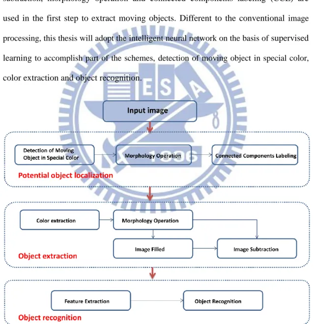
The intelligent recognition system is implemented in several steps as shown in Fig. 3.1, including potential object localization, character extraction and character recognition. Each step adopts some schemes of image processing, such as image
subtraction, morphology operation and connected components labeling (CCL) are
used in the first step to extract moving objects. Different to the conventional image
processing, this thesis will adopt the intelligent neural network on the basis of supervised
learning to accomplish part of the schemes, detection of moving object in special color,
color extraction and object recognition.
19
3.1 Detection of Moving Object in special color
This is the first part of potential object location. In usual, there are two fundamental steps to detect a moving object of special color, which include moving object detection and color extraction. Both steps are often processed separately, but this thesis presents a scheme based on the artificial neural network to extract the color and detect the moving object simultaneously.To detect a moving object from a sequence of images, the algorithm is shown as below:
th t t th t t m I y x I y x I I y x I y x I y x I , , 0 , , 1 , 1 1 (3.1)where It(x,y) and It1(x,y) represent the images at the time t and t1 and Ith is the
threshold. It is clear that Im(x,y) is a binary image. To detect a special color in the
following ranges:
Imo s c( ,x y) Ic( ,x y) |tB x y( , (3.2) ) where Ic represent the color in the image and we choose green for example, Imosc
is the result of moving object in special color is shown in Fig. 3.2(d),
20
(c) (d)
Fig. 3.2 (a) Input image (T=t-1). (b) Input image (T=t).
(c) Moving detection ( . (d)Detection of moving object in special color (
In supervised learning, the training data are required as shown in Fig.
3.2(d).The RGB information is learned by the neural network structure in Fig. 3.3 based on the back-propagation. After learning, moving object of special color can be distinguished from the background according to the output value of neural network. Usually, a pixel of moving object of special color has an output value near to 1, while a pixel in the background has an output value near to 0. To efficiently extract the moving object of special color in an image, a threshold value should be carefully selected under the lighting condition of the environment being properly controlled.
21
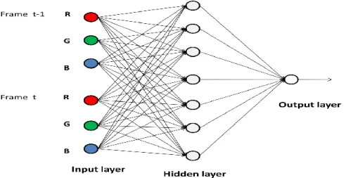
The neural network MCNN extracts a moving object of special color is shown in Fig. 3.3, which is composed of one input layer with 6 neurons, one hidden layer with 7 neurons, and one output layer with 1 neuron. The RGB values are sent into the 6 neurons of the input layer, represented by MC(p), where p=1,2,3 for frame t-1 and
p=4,5,6 for frame t. The p-th input neuron is connected to the q-th neuron, q=1,2,…,7,
of the hidden layer with weighting WMC1(p,q), which is a weighting array of
dimension 6×7. Besides, the q-th neuron of the hidden layer is also with an extra bias
bMC1(q). Finally, the q-th neuron of the hidden layer is connected to the output neuron
with weighting WMC2(q), q=1,2,…,7, and a bias bMC2 is added to the output neuron.
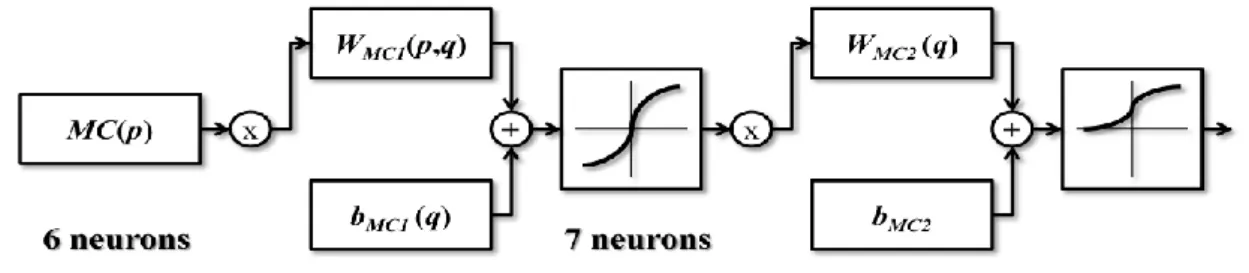
Let the activation function of the hidden layer be the hyperbolic tangent sigmoid transfer function, then the q-th output neuron OMC1(q) is expressed as:
1 1 1 2 ( ) 1, 1, 2,..., 7. 1+ 2 MC O q tansig n q q exp n q (3.3) where
6 1 1 1 1 ( , ) ( ) ( ) MC MC p n q W p q MC p b q
(3.4)Let the activation function of the output layer be the log-sigmoid transfer function, then the single output neuron OMC2 is expressed as:
2 2 2 1 ( ) 1+ MC O logsig n exp n (3.5) where 7 2 2 1 2 1 ( ) ( ) MC MC MC q n W q O q b
(3.6)22
Fig. 3.4.MCNN
3.2 Morphology operation
Three parts are using in this section, erosion; dilation and holes filling.
3.2.1 Erosion and Dilation
After applying color extraction, color regions are extracted from the original image, but some noise still exists therein. One of the conventional ways to eliminate noise regions is using the morphology operations. In the thesis, the noises are eliminated by the morphology erosion operation (2.14) expressed as
: ( )x
A B x B A (3.7)
where B is a disk-shaped structuring element with radius 4 as shown in Fig. 3.5(a) and the noises in image A with region smaller than B are erased after operation. However, some gaps may be also generated in isolated regions after erosion. In order to repair these gaps, further employ the morphology dilation operation (2.13) expressed as
: ( )ˆ
x
A C x C A (3.8)
where C is a disk-shaped structuring element with radius 6 as shown in Fig. 3.5(b) and the gaps in image A are repaired after operation. Fig. 3.6 shows an example of erosion and dilation using the structuring elements B and C.
23
(a) (b)
Fig. 3.3 (a) Structuring element B (b) Structuring element C
(a)
(b)
(c)
Fig. 3.4 Steps for morphology operations (a) Initial image (b) Result of erosion using structuring element B (c) Result of dilation using structuring element C
0 0 1 1 1 1 0 0 0 1 1 1 1 1 1 0 1 1 1 1 1 1 1 1 1 1 1 1 1 1 1 1 1 1 1 1 1 1 1 1 1 1 1 1 1 1 1 1 0 1 1 1 1 1 1 0 0 0 1 1 1 1 0 0 0 0 1 1 1 1 1 1 1 1 0 0 0 1 1 1 1 1 1 1 1 1 1 0 1 1 1 1 1 1 1 1 1 1 1 1 1 1 1 1 1 1 1 1 1 1 1 1 1 1 1 1 1 1 1 1 1 1 1 1 1 1 1 1 1 1 1 1 1 1 1 1 1 1 1 1 1 1 1 1 1 1 1 1 1 1 1 1 1 1 1 1 1 1 1 1 1 1 1 1 1 1 1 1 1 1 1 1 1 1 1 1 1 1 1 1 1 1 1 1 0 1 1 1 1 1 1 1 1 1 1 0 0 0 1 1 1 1 1 1 1 1 0 0
24
3.2.2 Holes filling
In the current application, it is appropriately called conditional dilation or inside connected components. A hole may be defined as a background region surrounded by connected border of foreground pixels. In this section, we develop an algorithm based on set dilation, complementation, and intersection for filling holes in an image. Let A denote a set whose elements are 8-connected boundaries as in Fig. 3.7(a), each boundary enclosing a background region. Given a point in each hole, the objective is to fill all the holes with 1.
We begin by forming an array, X0, of 0s, expect at the locations in X0
corresponding to given point in each hole, which we set to 1. Then, the following procedure fills all holes with 1s:
( 1 ) c k k X X B A 1 , 2 , 3 , . . . k (3.9) where B is the symmetric structuring element in Fig. 3.7(c). The algorithm terminates
at iteration step k if Xk=Xk-1.The set then Xk contains all the filled holes. The set union
of Xk and A contains all the filled holes and their boundaries. Fig. 3.8(a) shows an
example image, and Fig. 3.8(b) shows the result of the hole filling.
(a) (b) (c) Fig. 3.7(a) A (b) Ac (c) B
25
(a) (b) Fig.3.8
Fig.3.8 (a) Original frame. (b) Result of holes filling.
3.3 Connected Components Labeling
After morphology operation different components are identified by using Connected Components Labeling (CCL), which is often used in computer vision to detect connected regions containing 4 or 8 pixels in the binary digital image. In this thesis, the 4-pixel connected component will be used to label potential face regions.
Fig. 3.9 Scanning the image.
r t p r t p r t p
26
The 4-pixel connected CCL algorithm can be partitioned into two processes, labeling and componentizing. During the labeling, the image is scanned pixel by pixel, from left to right and top to bottom as shown in Fig. 3.9, where p is the pixel being processed, and r and t are respectively the upper and left pixels to p. Defined v() and
l() as the binary value and the label of a pixel. If v(p)=0, then move on to next pixel, otherwise, i.e., v(p)=1, the label l(p) is determined by following rules:
R1. For v(r)=0 and v(t)=0, assign a new label to l(p). R2. For v(r)=1 and v(t)=0, assign l(r) to l(p), i.e., l(p)=l(r). R3. For v(r)=0 and v(t)=1, assign l(t) to l(p), i.e., l(p)=l(t).
R4. For v(r)=1, v(t)=1 and l(t)=l(r), then assign l(r) to l(p), i.e., l(p)=l(r). R5. For v(r)=1, v(t)=1 and l(t)≠l(r), then assign l(r) to both l(p) and l(t), i.e., l(p)=l(r) and l(t)= l(r).
For example, after the labeling process, Fig. 3.10(a) is changed into Fig. 3.10(b). It is clear that some connected components contain pixels with different labels. Hence, it is required to further execute the process of componentizing, which sorts all the pixels connected in one component and assign them by the same label, the smallest number among the labels in that component. Fig. 3.10(c) is the result of Fig. 3.10(b) after componentizing.
27
(a)
(b)
(c)
Fig. 3.10 Example of 4-pixel connected CCL. (a) Digital image. (b) Labeling. (c) Componentizing.
0 0 0 0 0 0 0 0 0 0 0 0 0 0 1 1 0 1 0 0 0 0 0 0 1 1 0 1 0 0 0 0 0 1 1 0 0 0 0 0 0 0 0 1 1 0 0 0 1 0 0 1 1 1 0 0 1 0 1 0 1 1 1 1 0 0 1 1 1 0 0 0 0 0 0 0 0 0 0 0 0 0 0 0 0 0 0 0 0 0 0 0 0 0 1 1 0 2 0 0 0 0 0 0 1 1 0 2 0 0 0 0 0 1 1 0 0 0 0 0 0 0 0 1 1 0 0 0 3 0 0 4 1 1 0 0 5 0 3 0 4 1 1 1 0 0 5 3 3 0 0 0 0 0 0 0 0 0 0 0 0 0 0 0 0 0 0 0 0 0 0 0 0 0 1 1 0 2 0 0 0 0 0 0 1 1 0 2 0 0 0 0 0 1 1 0 0 0 0 0 0 0 0 1 1 0 0 0 3 0 0 1 1 1 0 0 3 0 3 0 1 1 1 1 0 0 3 3 3 0 0 0 0 0 0 0 0 0 0 0
28
3.4 Character extraction from Potential Region
Two main parts in this section, color extraction and character extraction.3.4.1 Color extraction
This system presents the color extraction based on artificial neural network. In supervised learning, the training data of the colors are required and obtained from images composed of object and background. Examples of training data are shown in Fig. 3.11, where each original image is separated into object region and background. The RGB information is learned by the neural network structure in Fig. 3.12 based on the back-propagation. After learning, the pixels of green color can be distinguished from the background according to the output value of neural network. Usually, a pixel of color has an output value near to 1, while a pixel in the background has an output value near to 0. To efficiently extract the color in an image, a threshold value should be carefully selected under the lighting condition.
(a) (b) (c)
Fig. 3.11 Examples of training data for skin color extraction. (a) Original image (b) Skin color region (c) Background
29
Fig. 3.12 Neural network structure for color extraction.
For green color extraction neural network (GNN) based on the structure in Fig. 3.12, there include one input layer with 3 neurons, one hidden layer with 5 neurons, and one output layer with 1 neuron. The RGB values are sent into the 3 neurons of the input layer, represented by G(p), p=1,2,3, correspondingly. The p-th input neuron is connected to the q-th neuron, q=1,2,…,5, of the hidden layer with weighting WG1(p,q).
Hence, there exists a weighting array WG1(p,q) of dimension 3x5. Besides, the q-th
neuron of the hidden layer is also with an extra bias bG1(q). Finally, the q-th neuron of
the hidden layer is connected to the output neuron with weighting WG2(q), q=1,2,…,5,
and a bias bG2 is added to the output neuron.
Let the activation function of the hidden layer be the hyperbolic tangent sigmoid transfer function and the q-th output neuron OG1(q) is expressed as:
1 1 1 2 ( ) 1, 1, 2,...,5. 1+ 2 G O q tansig n q q exp n q (3.10) where30
3 1 1 1 1 ( , ) ( ) ( ) G G p n q W p q G p b q
(3.11)Let the activation function of the output layer be the log-sigmoid transfer function and the single output neuron OG2 is expressed as:
2 2 2 1 ( ) 1+ G O logsig n exp n (3.12) where 5 2 2 1 2 1 ( ) ( ) G G G q n W q O q b
(3.13)The above operations are shown in Fig. 3.13.
3.4.2 Character extraction
After detect the green color of the word card, the word card will be abstract. Here are three steps in this chapter to extract character from the word card. First, some noise still exists therein. Using erosion (3.7) structuring element with radius 2 and dilation (3.8) structuring element with radius 3 will reduce noises and get the frame as shown in Fig. 3.14(a).
The word card is thus achieved as a binary image with the shape of the character on it as shown in Fig. 3.14(a).The character will be extracted by using holes filling
31
and image subtraction.
In the first, generate a plain binary card with holes filling, the holes of the word card will be filled as shown in Fig. 3.14(b). Then, by generating a plain binary card, the character on the word card can be extracted by subtracting the plain binary card. The result is shown in Fig. 3.14(c).
(a) (b) (c) Fig. 3.14 (a) Result after reduce the noise.
(b)Image with hole filled. (c) Image subtraction.
3.5 Character recognition
Two parts are using in this section, Feature extraction and classification.
3.5.1 Feature extraction
After object extraction, the character recognition is executed as the following step, whose performance will directly affect the overall accuracy rate. There are two main parts of the character recognition, one is feature extraction and the other is classification. This section will focus on the feature extraction [16]. In this thesis, we create a system which can deal with not only translation and rotation problem but also geometric deformation, like affine deformation.
32
The features to be extracted are set to be I1 to I12 which will be used for
character recognition and defined in the followings. The first feature is the normalization of the moment of inertia of the image, defined as [17]
N i y i x i C y C x N I 1 2 2 2 1 1 (3.14) where Cx and Cy are the location of centroid, xi; yi are the image pixel coordinates ofthe object, and N is the total number of pixels in the object. Clearly, this feature is scaling invariant.
The second feature I2is similar with I1, another feature possessing scaling
invariance, and defined as
2 2 min ( ) *10 * maj N I L L (3.15)
where Lmaj is the major axis length and Lminis the minor axis length, which are the length if the smallest ellipse as shown in Fig.3.15. Using equation (3.15) will let the value of the percentage of pixel in the areaseparated clearly.
33
The third feature I is called the Euler number, which is a measure of the 3
topology of an image and defined as the total number of objects in the image minus the number of holes in those objects. For example, 0’s Euler number is 0 and 8’s Euler number is 1.
For the features I and 4 I , which are defined as the normalized difference of 5
arcs outside the character of the fourth and the fifth circles. From (2.15), both can be expressed as 42 41 4 4 52 51 5 5 2 2 d d I r d d I r (3.17) (3.18)
For the rest of features from I to 6 I , they are defined as 12
5
k
k M
I , k=6,7,...,12 (3.19)
which adopts the definition Mi to represent the number of arcs of i-th circle outside the character shown in section 2.6. Clearly, these features are related to 1st to 7th circles. As for the 8th circle, it is neglected since the 8th circle in all the characters are almost the same.
34
3.5.2 Classification with Neural Networks
In this thesis, there are 43 neurons used for the ANN structure shown in Fig. 3.16, called the Character-recognition neural network or CRNN in short, which contains 12 neurons from m1 to m12 for input layer, 17 neurons for hidden layer, and 4
neurons from e1 to e4 for output layer. The inputs of the neurons CRi, i=1, 2,…, 12, are
the feature extract in chapter 3.5.1 The outputs of the neurons ei, i=1, 2,…, 4, are the
results corresponding each character. The learning process of CRNN are shown in Fig. 3.6(b), from left to right and downwards for the entire image.
Fig. 3.16 CRNN structure.
For ENN based on the structure in Fig. 3.16, the gray level values, represented by CR(p), p=1,2,…,12, are sent into the 12 neurons of the input layer, correspondingly. The p-th input neuron is connected to the q-th neuron of the hidden layer with weighting WCR1(p,q). Hence, there exists a weighting array WCR1(p,q) of dimension
12x17, p=1,2,…,12 and q=1,2,…,17. Besides, the q-th neuron of the hidden layer is also with an extra bias bCR1(q), q=1,2,…,17. Finally, the q-th neuron of the hidden
35
layer is connected to the output neuron with weighting WCR2(q,r), q=1,2,…,17 and r=1,2,…,4. The r-th neuron of the output layer is also with an extra bias bCR2(r) ,
r=1,2,…,4.
Choose the output of the q-th neuron in the hidden layer as the following hyperbolic tangent sigmoid transfer function
1 1 1 2 ( ) 1, 1, 2,...,17. 1+ 2 CR O q tansig n q q exp n q (3.19)where n1(q) is the input of the q-th neuron obtained as:
12 1 1 1 1 ( , ) ( ) ( ) CR CR p n q W p q CR p b q
(3.20)For the output layer, its r-th neuron is selected to be the following log-sigmoid transfer function
2 2 2 1 ( ) , 1, 2,..., 4. 1+ CR O r logsig n r r exp n r (3.21)where the input n2(r) of the r-th neuron is attained as:
17 2 2 1 2 1 ( , ) ( ) ( ) CR CR CR q n r W q r O q b r
(3.22)The above operations are shown in Fig. 3.17.
36
Chapter 4 Experiments
In this chapter, the experiment results of the system are present in the first part and the environment is set in our lab. In the chapter, some additional finding will be described in the second part and the execution time will be discussed at the third part. The proposed algorithm will be obtained by MATLAB R2010b.
4.1 Part I: Result of Each Steps
In the previous chapters, three main steps of the proposed system are introduced. In this part, the experiment results of each step will be expressed and character recognition results will be separated into feature extraction and classification.
4.1.1 Result of Potential Object Localization
For this system, there are three steps in potential object localization. Detection of moving object in special color, morphology operation and connected components labeling are used in to classify the potential region. First, Detection of moving object in special color extract target pixels from two input color image with time difference, which with the size 320x240 pixels. Two input color images are shown in Fig. 4.1(a) and Fig. 4.1 (b), the result image is shown in Fig. 4.2. After detection of moving object in special color extraction, there are still many noise in the scene, to reduce the noise, morphology operation is applied to eliminate small area and to clear the connect region as shown in Fig. 4.3(a),(b). To find out the potential regions, the CCL is applied as shown in Fig. 4.4 and more example for moving object extraction are shown in Fig. 4.5.
37
(a) (b)
Fig. 4.1(a)Input image (T=t-1). (b)Input image (T=t)
Fig. 4.2 Detection of moving object in special color.
(a) (b) Fig. 4.3 (a) Erosion. (b) Dilation.
38
Fig. 4.5 More example for moving object extraction. (a) Detection of moving object in special color. (b) Result after morphology operation. (c) Result after CCL
4.1.2 Result of Character extraction
After find out the potential regions, the next step is to extract the regions from the original frame with the same potential regions, shown in Fig. 4.6(a). In character extraction, the result will show how to find the character in potential regions. The first step in character extraction used color as the feature to find the plate as shown in Fig. 4.6(b). After color extraction, noise reduce is shown in Fig. 4.6(c) and image filled is shown in Fig. 4.6(d).We subtract the plate with the image filled plate and using CCL classify the largest object to character. The result is shown in Fig. 4.6(e) and more examples for character extraction are shown in Fig. 4.7.
39
(a) (b) (c) (d) (e) Fig. 4.6 (a) Potential region(b)color extraction.
(c)Reduce the noise. (d) Filled image. (e) Character extraction.
(a) (b) (c) (d) (e) Fig. 4.7 More example for character extraction. (a) Potential region. (b) Color extraction. (c)Reduce the noise. (d) Filled image. (e) Character extraction.
4.1.3 Result of Feature extraction
In this section, there are 4 cases which would be discussed for the feature extraction and the character “4” will used as an example. In case 1, consider the feature with 9 different angles from angle -40 to angle 40 with the same image size which is 315×300, the results in case 1 are shown in Table 4.1. In Case 2, consider the feature with different scale from 540×488 to 63×61 with the same aspect ratio, the results in case 2 are shown in Table 4.2. In Case 3, consider the feature with different
40
aspect ratio from shorten the axis and the results in case 3 are shown in Table 4.3. As Table 4.1 shown, the parameters I1~I12 are rotation-invariant. Table 4.2 shows, when
the pattern is large enough, parameter’s values will be very similar. Therefore, the parameters can achieve invariance under translation, rotation, and scaling. As shown in Table 4.3, although the value of will greatly change with the different aspect ratio. With the different proportion as the value of I2 and I3, I8~I12 may change as well .
Therefore, when the character is different, even if different angle of rotation, different sizes or aspect ratio, the proposed system still can excellent to recognize which character it is.
Table. 4.1 Same image size with different angle.
41
Table. 4.3 Different aspect ratio with the original size is 315×300
4.1.4 Result of Classification
The experiment results as shown in Fig. 4.8, the binary pictures are the characters after extraction and the classification results are at the left side. As shown in pictures, even if different angle of rotation, different sizes, noises or aspect ratio, the proposed system can excellent to recognize which character it is.
42
To compare the performance of the classification and then discusses 2 cases concerning the classification. In Case 1, consider the accuracy rates with 3 kinds of different training data. In Case 2, consider the accuracy rates with 2 kinds of different input neurons.
For training the Character-recognition neural network or CRNN in short, the thesis uses 137700 training data as shown in Fig. 4.9, with different size, rotation, translation, tilt and different aspect ratio and 6000 testing data. The accuracy rate is shown in Table 4.4. CRNN2 and CRNN3 are using the same structure with different training data. Clearly, the more training data will get the higher accuracy rate.
In Case 2, two kinds of CRNN are discussed, the CRNN4 is using the features without neglected the number of arcs of 8-th circle outside the character and CRNN5 is using the features with neglected the number of arcs of 7-th and 8-th circle outside the character. Clearly, although the error in CRNN4 is fewer, there are almost no different in accuracy rate between CRNN and CRNN4. Consider to neglected another feature, neglected the I12 can get the best accuracy rate is 99.0%.
43
Table. 4.4 Different training data with CRNN
training data testing data error Accuracy rate
CRNN 137700 6000 232 99.6%
CRNN2 85262 6000 687 88.5%
CRNN3 23000 6000 1344 77.6%
Table. 4.5 Different condition with CRNN
Condition training data testing data error Accuracy rate CRNN X 137700 6000 232 99.6% CRNN4 With I13 137700 6000 193 99.7% CRNN5 Without I12 137700 6000 583 99.0%
4.2 Part II: Intelligent system
Three intelligent neural networks are respectively proposed to detect moving word card in special color, to extract color and to recognize characters. In the research, we find out that supervised learning neural networks can replace the algorithm like morphology operation and detect moving object in two or more special colors. Fig.4.10 shows the system flowchart. Blue colors are the parts we use with intelligent neural networks and the yellow parts can be used either. The experiment result about morphology operation with intelligent neural networks will be expressed, considering the executing time, we don’t use all of the intelligent neural networks.
44
Fig.4.10 System flowchart.
4.2.1
Morphology operation with Artificial Neural
Network
This chapter presents the morphology operation based on the artificial neural network, which structure is similar to CRNN as shown in Fig. 4.11, called morphology-operation neural network or MONN in short. MONN contains 25 neurons from m1 to m25 for input layer, 10 neurons for hidden layer with the
log-sigmoid function, and 9 neurons with from e1 to e9 for output layer log-sigmoid
transfer function. The inputs of the neurons mi, i=1, 2,…, 25, are logical value of a
5x5 range retrieved from the original image as shown in Fig. 4.12(a). The outputs of the neurons ei, i=1, 2,…, 9, are the morphology operation results corresponding the
central 9 pixels of the 5x5 range. The learning process of MONN based on the 5x5 range for the morphology operation as shown in Fig. 4.12(b), from left to right and downwards for the entire image.
45
Two kinds of morphology operation output pair are used, erosion (3.9) structuring element with radius 3 called MONNE and dilation (3.10) structuring element with radius 4 called MONND. Two kinds of morphology-operation neural network used the same artificial neural network structure which shown in Fig. 4.11. Fig. 4.13 shows an example of erosion and dilation using the MONNE and MONND.
Fig.4.11 Neural network structure for morphology operation.
m1 m2 m3 m4 m5 m6 m7 m8 m9 m10 m11 m12 m13 m14 m15 m16 m17 m18 m19 m20 m21 m22 m23 m24 m25 (a) (b)
Fig. 4.12 (a) Square block (b) Scanning the image.
m2 m1 e1 e2 e9 m3 e3 m24 m23 m25 Input layer Hidden layer Output layer
46
(a) (b) (c) Fig. 4.13 (a) Original image.
(b) The result with using MONNE. (c) The result with using MONND.
4.2.1 Detect Moving Object in Several Colors with
Artificial Neural Network
In this experiment, we implement supervised learning artificial neural network that structure is same as MCNN as shown in Fig. 3.3, called several color neural network or SCNN in short. SCNN contains 6 neurons for input layer, 7 neurons for hidden layer with the log-sigmoid function, 1 neuron for output layer with the log-sigmoid function.
47
Two kinds of situation of output pair are used, the one is moving object detection (SCNN1) and the other is moving object detection with green and pink color (SCNN2). Two kinds of SCNN neural network used the same artificial neural network structure which is same as MCNN as shown in Fig. 4.15. Fig. 4.16 shows an example of using the SCNN1 and SCNN2.
(a) (b) (c)
Fig. 4.15 (a) Input image (T=t-1). (b) (T=t). (c) The result with using SCNN1.
(a) (b) (c) Fig. 4.16 (a) Input image (T=t-1).
48
4.3 Part III: Execution time
In the previous chapter, we find out that supervised learning neural network can replace the algorithm like morphology operation and detect moving object in two or more special colors. The experiment in the section will show each execution time. Table 4.6 shows the MONNE’s execution time in different block sizes, Table 4.7 shows the SCNN1’s execution time in different block sizes and Table 4.8 will show the total execution time with different condition.
We find out that fewer outputs is a absolute way and input size must be proportional to the operation radius if we want to get the better performance. Although MONNE and MONND have different operations output design, with the same neural network structure, the execution time will be almost the same. As Table 4.6 and Table 4.7 shown, MONNE’s execution time is between 0.032sec~0.062sec and SCNN1’s execution time is between 0.036sec and 0.038sec. The executing time of morphology operation and image subtraction is quiet shorter in MATLAB R2010b, only 0.0025sec and 0.0001sec, respectively. As shown in Table 4.8, when system using MONNE, MONND and SCNN1 will let the execution time twice longer and the screen will be discontinuous. Considering the executing time, we don’t use all of the intelligent neural networks in this thesis.
49
Table 4.6 MONNE’s execution time in different block sizes.
Block size Input neuron Hidden neuron Output neuron Extraction time
m=4, n=2 16 10 2 0.046sec
m=5, n=3 25 10 9 0.037sec
m=7, n=5 49 10 9 0.032sec
m=9, n=5 81 10 25 0.062sec m=9, n=7 81 10 25 0.035sec
Table 4.7 SCNN1’s execution time in different block sizes.
Block size The time to generate input
calculate time The time to generate output
total time
m=1, n=1 0.004 0.03 0.004 0.038sec
m=3, n=3 0.002 0.032 0.002 0.036sec
Table 4.8 Compare average execution time in different condition.
Average time Average frame rate
Without Character Recognition 0.04sec 25
With Character Recognition 0.14sec 6.6
System with MONNE and MONND 0.22~0.27sec 3.7~4.5
50
Chapter 5
Conclusions and Future Works
The purpose of this thesis is to build up a system for children to learn words in an interactive way. In this thesis, the developed intelligent system can recognize the character correctly in a moving word card from a sequence of images.
The system is designed in three steps, including potential object localization, character extraction and character recognition. In the first step, it is required to detect the moving object in special color, or word card, and then determine the location of the word card in the image. A supervised learning neural network (MCNN) is used to extract the color and detect the moving object simultaneously. After applying the MCNN, the region of the word card in green color is extracted from a sequence of images; unfortunately, some noise exists therein. Using morphology operation and connected components labeling (CCL), the noise is removed and the region of the word card could be located correctly.
In the second step, use another supervised learning neural network (GNN) to, and then apply the morphology operation to reduce noise. The word card is thus achieved as a binary image with the shape of the character on it. By generating a plain binary card, the character on the word card can be extracted by subtracting the plain binary card. Besides, the total number of character’s pixels is used to determine whether the result is a character or not. In the third step, a scheme based on a set of concentric circles is adopted to extract the character features, and then feed the features into the third supervised learning neural network (CRNN) to recognize which word it is, the designed neural networks CRNN can robustly identify characters in